Overview
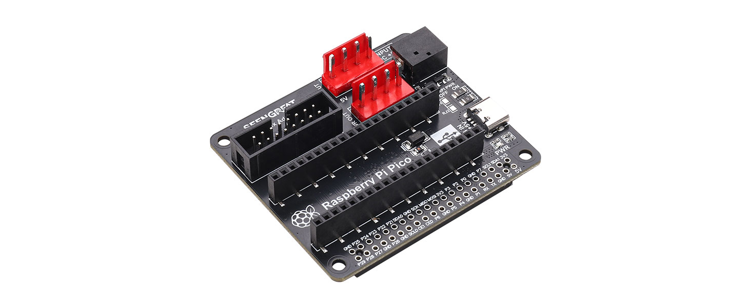
RGB Matrix Adapter Board is a product that is convenient for users to quickly wire the RGB LED matrix panel with HUB75 interface to Raspberry Pi series motherboards and Raspberry Pi Pico. The main connectors of the RGB Matrix Adapter Board are:
1. Two power input ports, namely USB TYPE-C 5V/4A and DC-044 Jack 5V/8A. Users can choose one of the power input ports according to their own usage.
2.Two VH-4P 5V/4A power output connectors with a pitch of 3.96mm can supply power to two RGB LED matrix panel.
3.One HUB75 interface, which can be directly connected to the HUB75 interface of the RGB LED matrix panel.
4. A set of Raspberry Pi 40pin GPIO female header, which can be connected to the Raspberry Pi series motherboard.
5. A set of Raspberry Pi Picofemale headerfor easy access to Raspberry Pi Pico.
Parameters
- Operating voltage: 5V
- Power input connector: USB TYPE-C 5V/4A or DC-044 Jack 5V/8A
- Power output connector: Two VH-4P(3.96mm pitch) power supply connectors for RGB LED matrix panel 5V/4A
- RGB LED matrix panel interface: HUB75
- Data interface: Raspberry Pi 40pin GPIO or Raspberry Pi Pico female headers
- Onboard Raspberry Pi power supply selects 0-ohm resistor,The user only needs one power supply to simultaneously power both the panel and the Raspberry Pi.
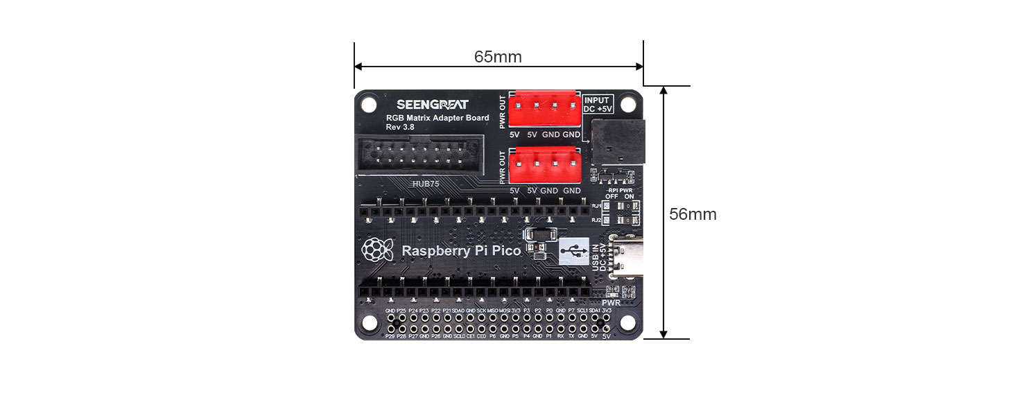
- Size: 65mm(Length) x 56.5mm(Width)
Usage
Notice:Please check the power supply to prevent reverse connection before powering on, and do not plug and unplug while working; Do not touch the core components with both hands directly during product operating, and do a good job of electrostatic protection
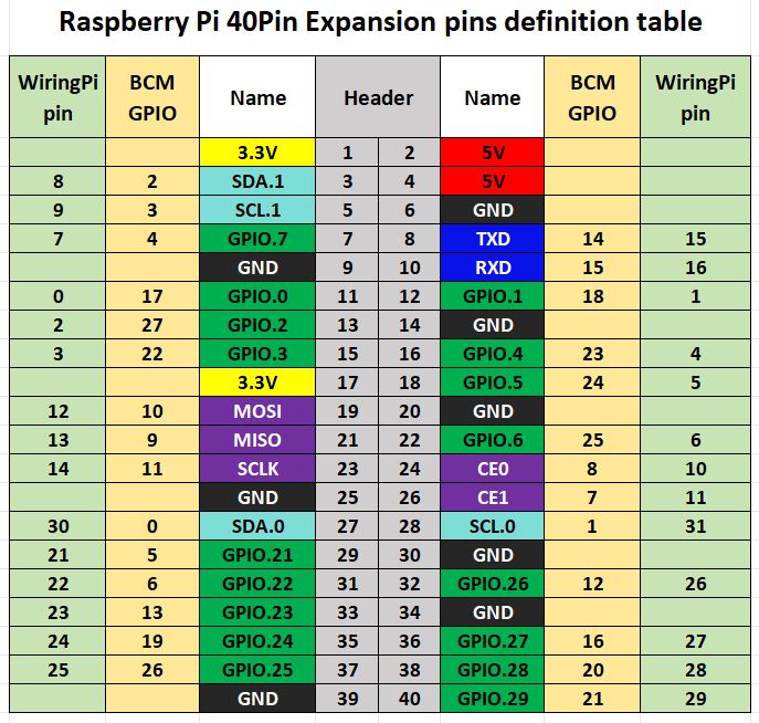
The wiring instructions of RGB Matrix Adapter Board, Raspberry Pi and RGB LED matrix panel
| Mark | Pin Description | BCM Number | Mark | Pin Description | BCM Number |
|---|---|---|---|---|---|
| R1 | R higher bit data | 11 | G1 | G higher bit data | 27 |
| B1 | B higher bit data | 7 | GND | Ground | GND |
| R2 | R lower bit data | 8 | G2 | G lower bit data | 9 |
| B2 | B lower bit data | 10 | E | E line selection | 15 |
| A | A line selection | 22 | B | B line selection | 23 |
| C | C line selection | 24 | D | D line selection | 25 |
| CLK | Clock input | 17 | LAT | Latch pin | 4 |
| OE | Output enable | 18 | GND | Ground | GND |
The wiring instructions of RGB Matrix Adapter Board, Pico and RGB LED matrix panel
| Mark | Pin Description | Pico Pin | Mark | Pin Description | Pico Pin |
|---|---|---|---|---|---|
| R1 | R higher bit data | GP02 | G1 | G higher bit data | GP03 |
| B1 | B higher bit data | GP04 | GND | Ground | GND |
| R2 | R lower bit data | GP05 | G2 | G lower bit data | GP08 |
| B2 | B lower bit data | GP09 | E | E line selection | GP22 |
| A | A line selection | GP10 | B | B line selection | GP16 |
| C | C line selection | GP18 | D | D line selection | GP20 |
| CLK | Clock input | GP11 | LAT | Latch pin | GP12 |
| OE | Output enable | GP13 | GND | Ground | GND |
Connector Definitions
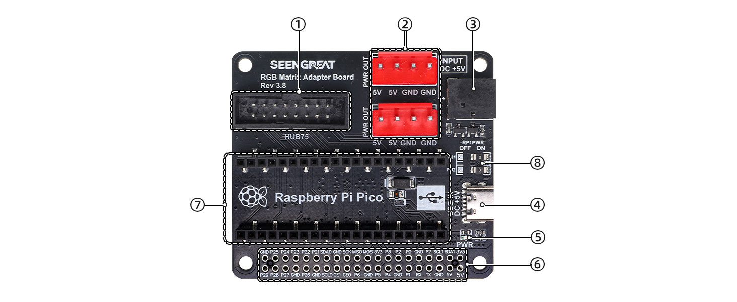
1. HUB75 interface
2. 2 sets of VH-4P RGB LED matrix panel power supply connector
3. DC-044 5V power input connector
4. USB TYPE-C 5V power input connector
5. Power Indicator
6. Raspberry Pi 40 pin GPIO connector
7. Raspberry Pi Pico connector
8. The Raspberry Pi power supply selects a 0-ohm resistor and is set to the "ON" state by default, meaning it powers the Raspberry Pi.
Usually, when using the RGB Matrix Adapter Board with Raspberry Pi 3, 4B+, we use a stacked 2*20 Pin female header to ensure the heat dissipation environment for the Raspberry Pi's processor.
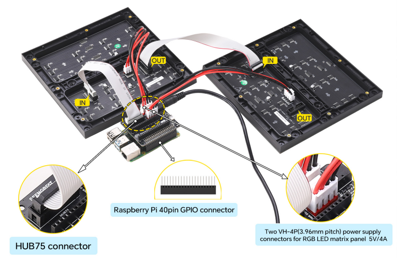
Raspberry Pi Connection Diagram
Note:
1. Regarding the applications and example codes for panel cascading, you can click the WIKI link of the corresponding specification panel in the Resources section at the bottom of this page to view them.
2. If you only need to connect one RGB matrix panel, you simply need to remove the right RGB matrix panel.
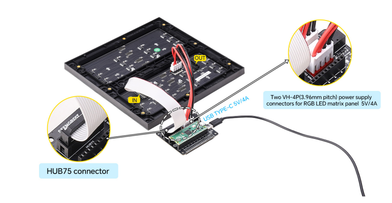 Raspberry Pi Pico Connection Diagram
Resources
Related Data Resources of RGB LED Matrix Panels
WIKI: RGB Matrix P3.0-64x64
WIKI: RGB Matrix P3.0-64x32
WIKI: RGB Matrix P2.5-64x32
