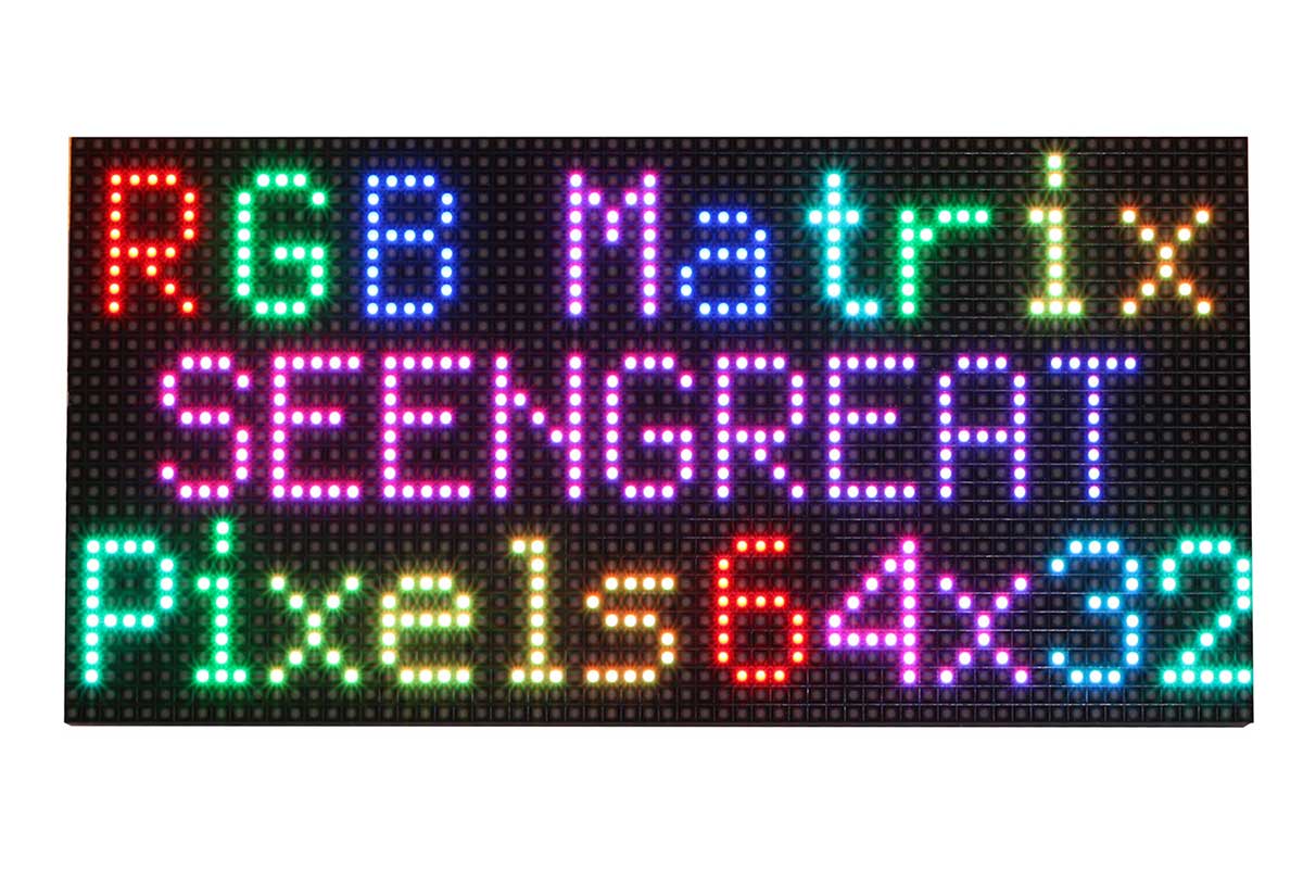
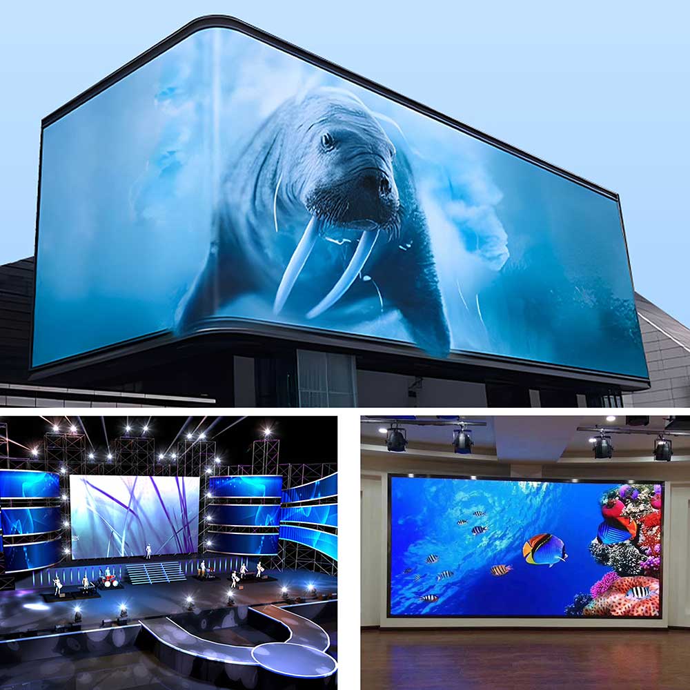
DIY Maker, Desktop Signboard, Wall Mount Display, Environment Monitor.
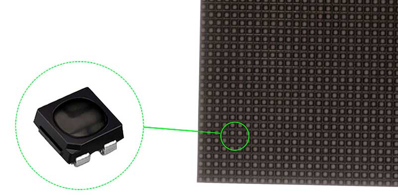
High qulity LED lights
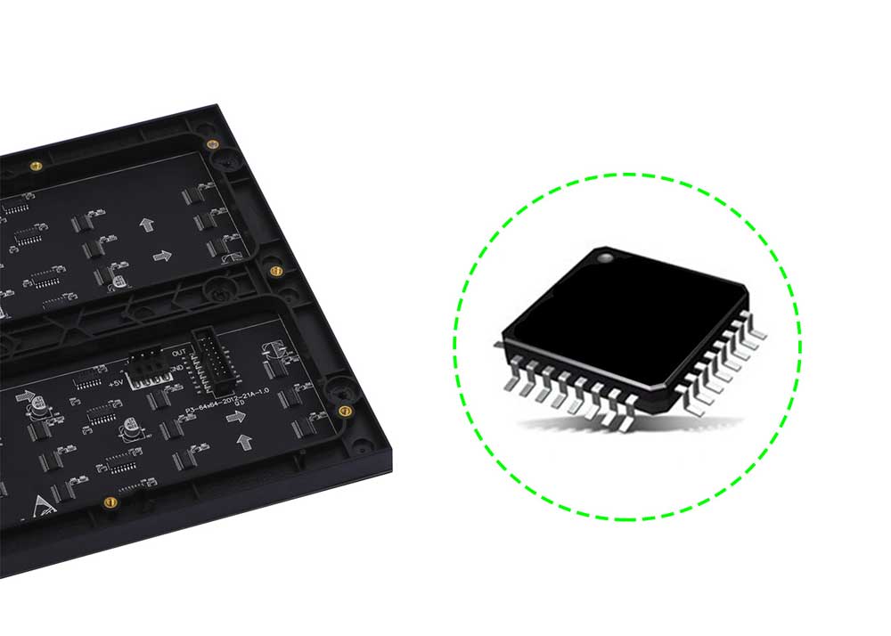
High qulity LED-driven chips
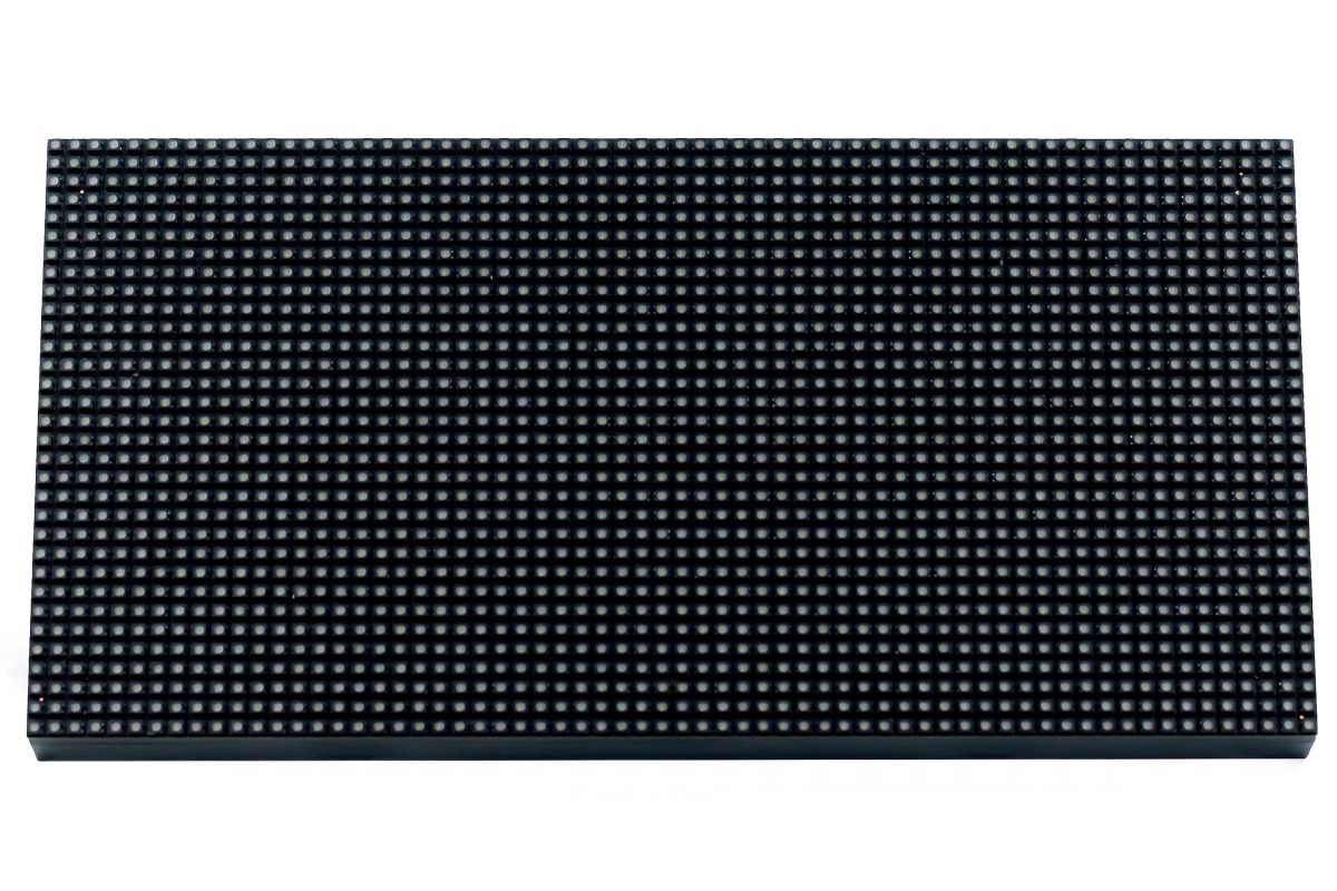
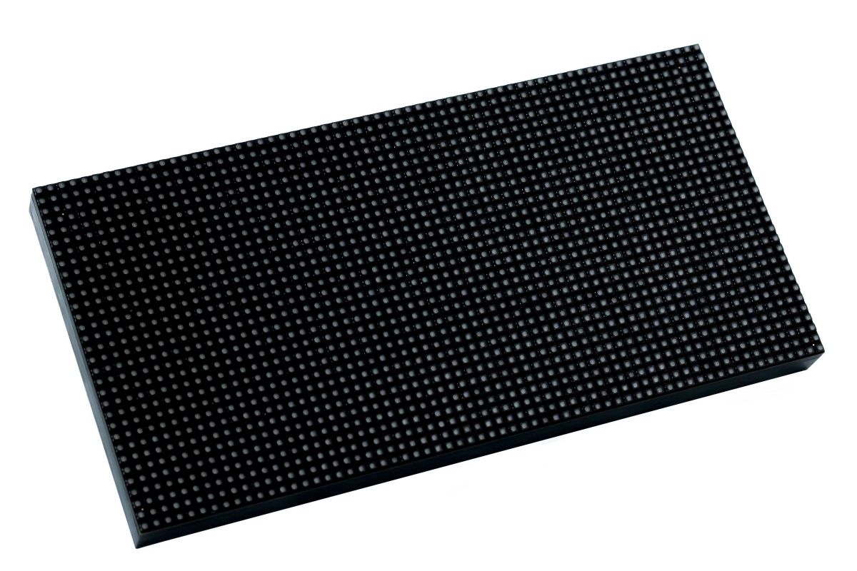
This matrix panel is a bare screen and needs to be displayed with the main control board such as Raspberry Pi, ESP32, and Arduino. If it is used for multi-screen cascading, please make sure that the power of each screen is 5V/2A. It offers open source demos and tutorials for makers or electronics enthusiasts to get started, or DIY secondary development into other desktop or wall-mounted display applications.
Features
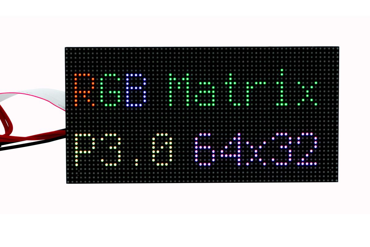
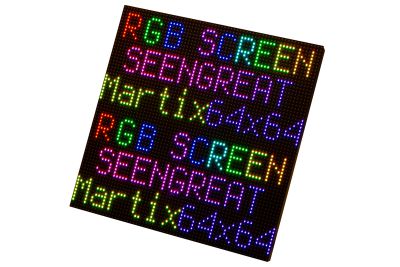
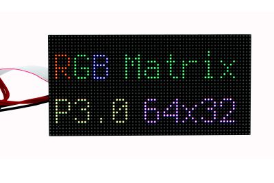
- On-board 64 x 32 full-color display LEDs
- 3.0mm pitch, displaying text, animation and colorful image
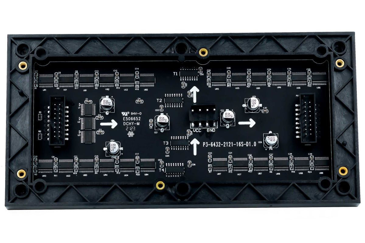
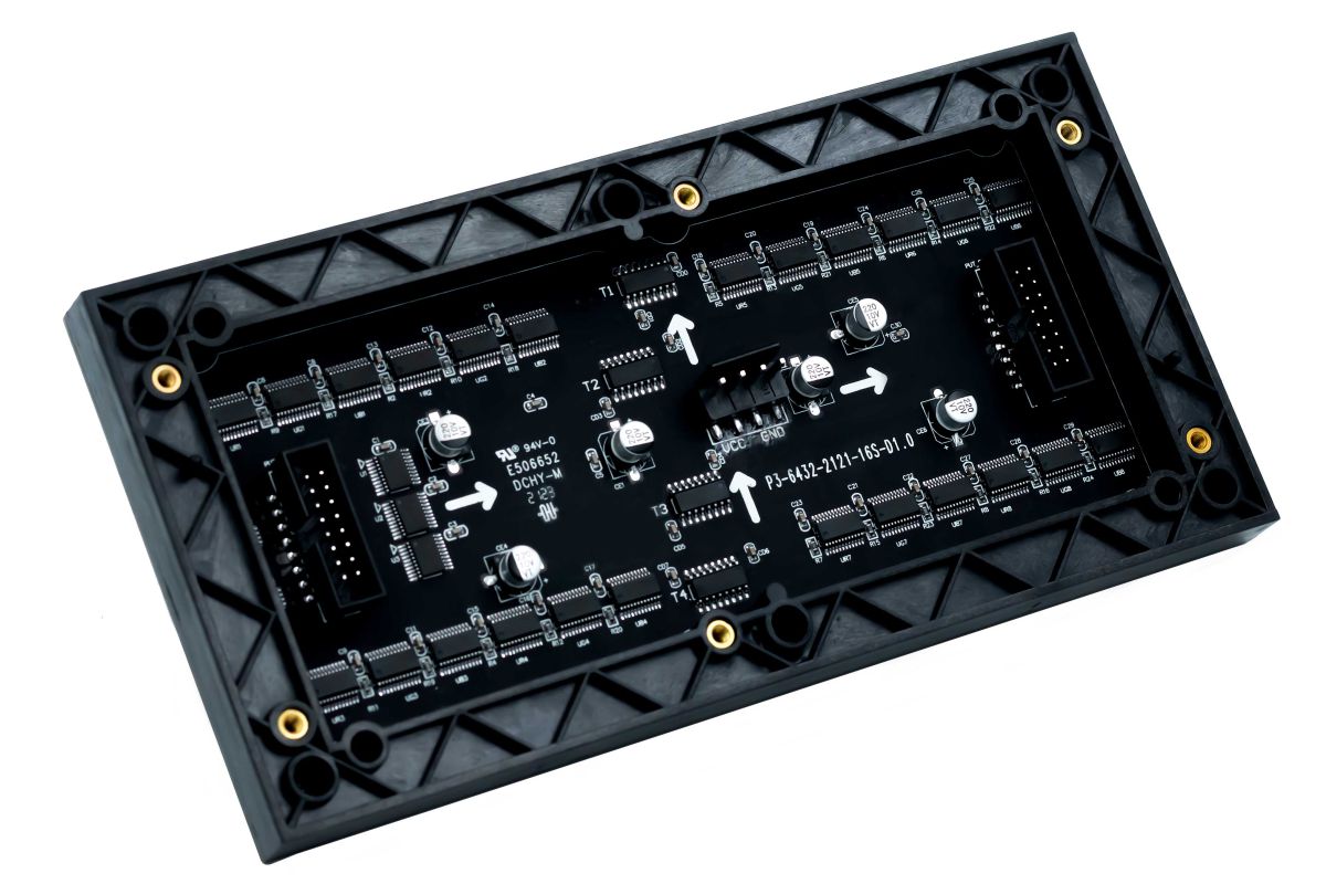
- Onboard two HUB75 interfaces, respectively for input and output. It can be cascaded multi-screen
- Providing open development resources and tutorials for the use of Raspberry Pi
Specifications
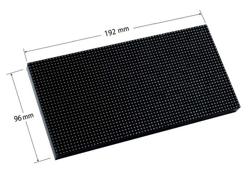
| Dimensions | 192mm(Length) x 96mm(Width) x 15mm(Height) |
| Pixels | 64x32 |
| Pitch | 3.0mm |
| Pixel Form | 1R1G1B |
| Viewing Angle | ≥160° |
| Interface | HUB75 |
| Control Type | Synchronization |
| Driving | 1/16 scan |
| Power Supply | 5V/2A |
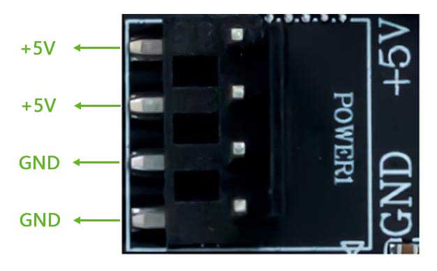
| Power Port | VH4 socket |
Definitions of Connectors
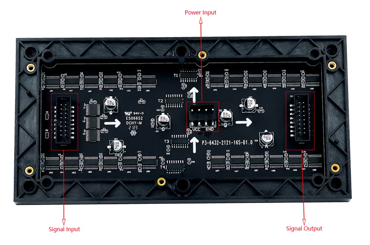
Power input:
Signal input/output:
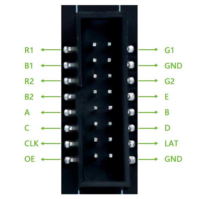
| R1 | R higher bit data | G1 | G higher bit data |
| B1 | B higher bit data | GND | Ground |
| R2 | R lower bit data | G2 | G lower bit data |
| B2 | B lower bit data | E | E line selection |
| A | A line selection | B | B line selection |
| C | C line selection | D | D line selection |
| CLK | clock input | LAT | latch pin |
| OE | output enable | GND | Ground |
WIKI
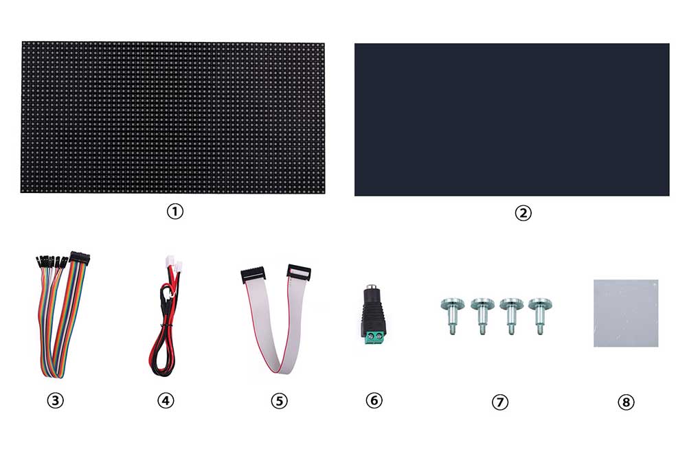
Package Contents
- 1. RGB full-color LED matrix panel x1
- 2. Dark brown acrylic front panel x1
- 3. 16P wire ~30cm x1
- 4. Power Cord x1
- 5. 16p Gray Ribbon x1
- 6. Power supply terminal adapter x1
- 7. Magnetic bolt x4
- 8. Double-sided tape x1