 I. Product Overview
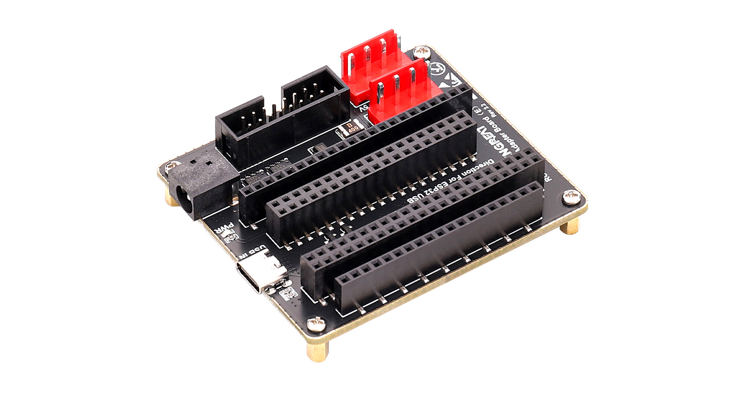
The RGB Matrix Adapter Board (E) is designed based on the ESP32-S3-DevKitC-1 and ESP32-DevKitC V4 development boards. It is specifically built for efficient data transmission and stable power management. This board is suitable for displaying text, graphics, animations, and more, helping users quickly bring various creative designs to life.
The adapter board integrates multiple key interfaces, providing both reliable power supply and stable data transmission.
II. Product Features
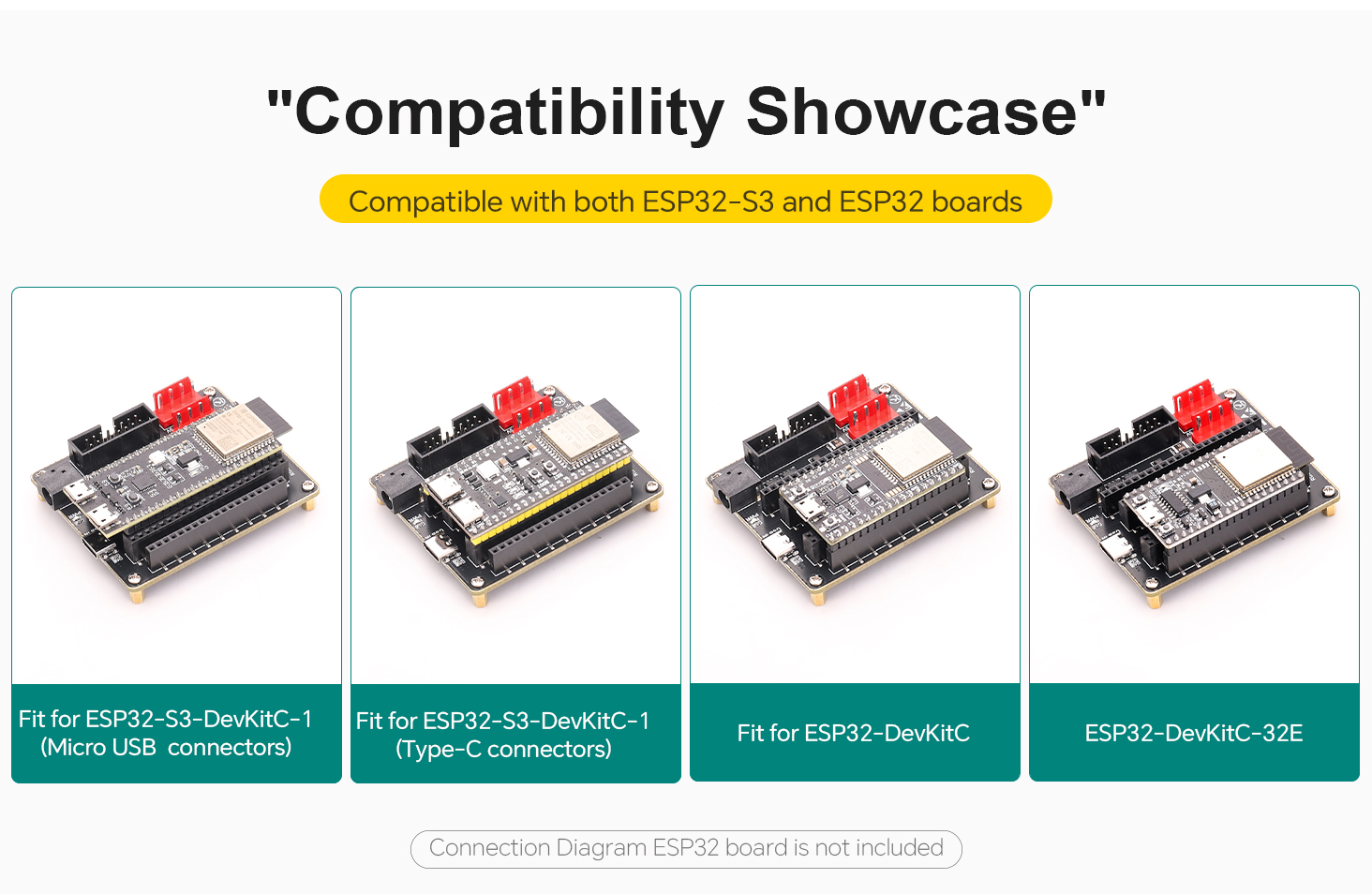
· Compatible with ESP32-DevKitC and ESP32-S3-DevKitC-1
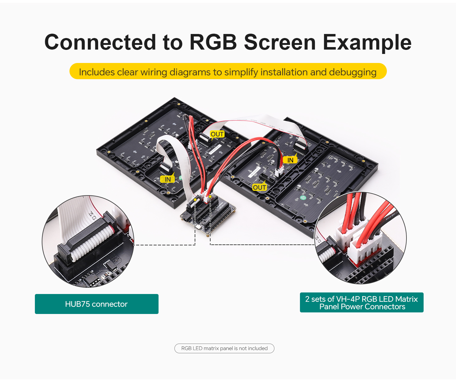
· Onboard two VH-4P (3.96 mm pitch) power connectors and HUB75 interface for RGB LED matrix panels
· Dual power input ports: USB Type-C 5V/4A or DC-044 5V/8A
· Gold-plated edge design for enhanced durability and aesthetics
III. Product Specifications
Item | Specification |
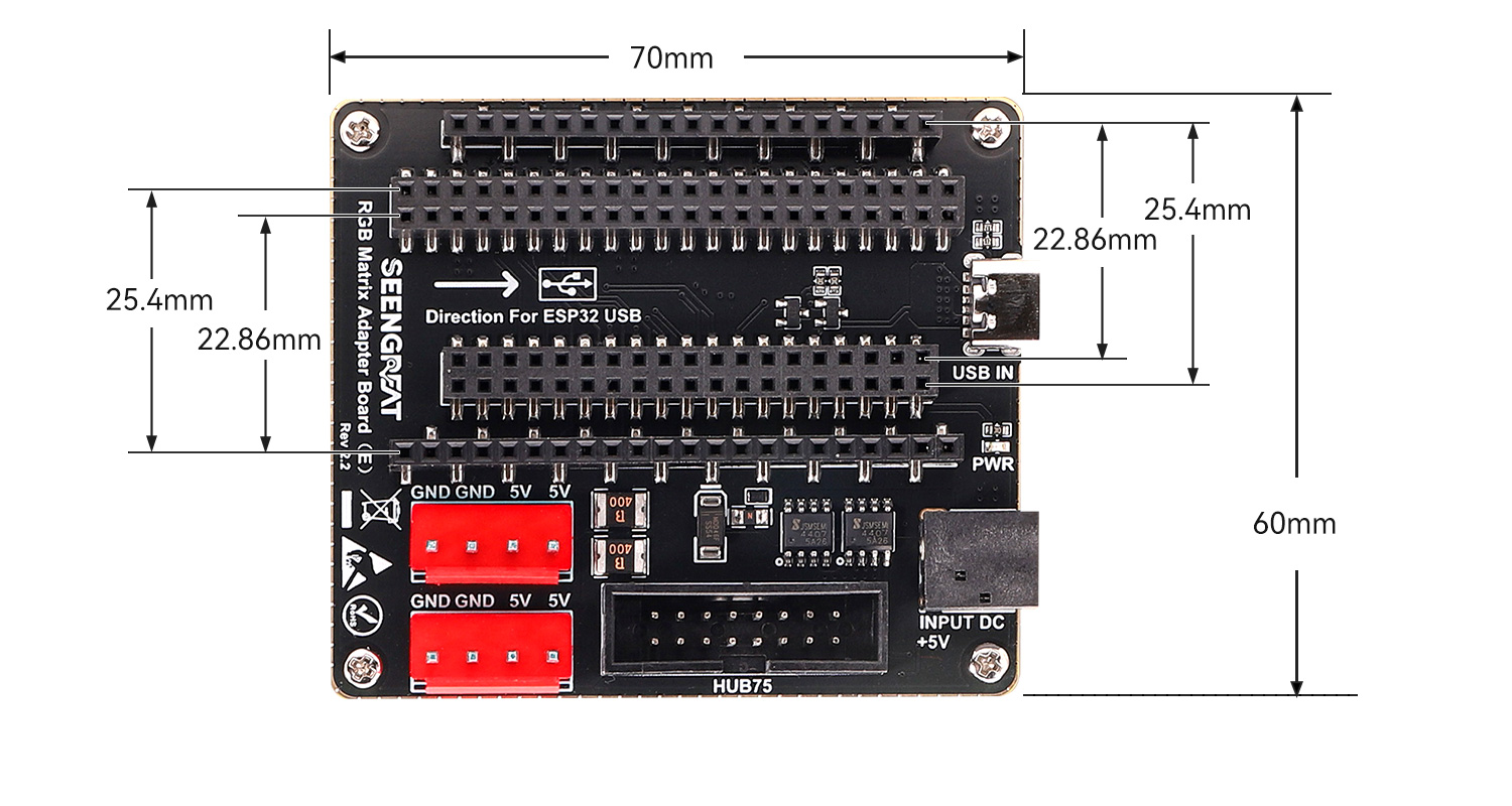
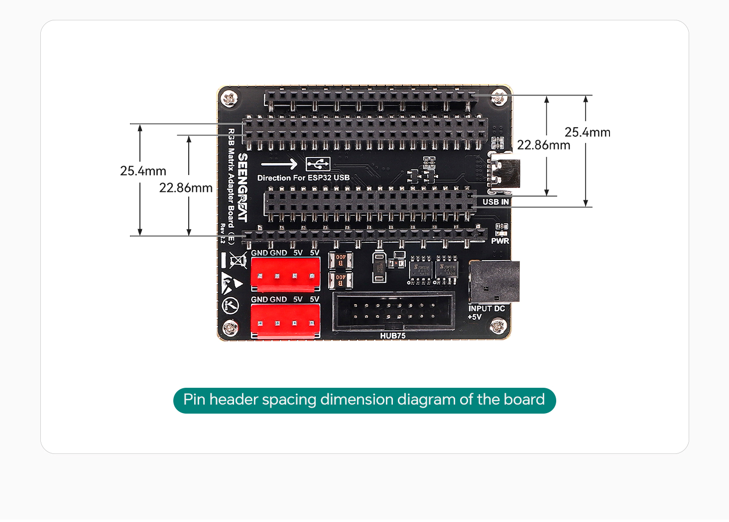
Dimensions | 70 mm (Length) × 60 mm (Width) |
Power Input Connectors | USB Type-C: 5V / 4A; DC-044: 5V / 8A |
Power Output Connectors | Two VH-4P (3.96 mm pitch) connectors, 5V / 4A each |
RGB LED Matrix Panel Interface | HUB75 |
Data Interfaces | ESP32-S3-DevKitC-1 connectors, ESP32-DevKitC connectors |
IV. Product Usage
4.1 Module Resource Profile
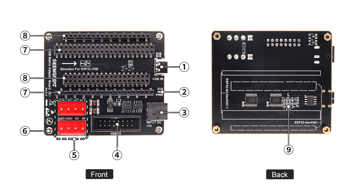
① USB connector (5V power input only)
② Power indicator LED
③ DC-044 5V power input connector
④ HUB75 connector
⑤ Two VH-4P connectors for RGB LED matrix panel power supply
⑥ M2.5 mounting holes
⑦ ESP32-S3-DevKitC-1 connector
⑧ ESP32-DevKitC connector
4.1.1 Wiring Diagram with ESP32-S3-DevKitC-1
Pin mapping for version V1.x
Mark | Description | Pin | Mark | Description | Pin |
R1 | R higher bit data | IO37 | G1 | G higher bit data | IO06 |
B1 | B higher bit data | IO36 | GND | Ground | GND |
R2 | R lower bit data | IO35 | G2 | G lower bit data | IO05 |
B2 | B lower bit data | IO0 | E | E line selection | IO04 |
A | A line selection | IO45 | B | B line selection | IO01 |
C | C line selection | IO48 | D | D line selection | IO02 |
CLK | Clock input | IO47 | LAT | Latch pin | IO38 |
OE | Output enable | IO21 | GND | Ground | GND |
Pin mapping for version V2.x
Mark Description Pin Mark Description Pin R1 R higher bit data IO18 G1 G higher bit data IO8 B1 B higher bit data IO17 GND Ground GND R2 R lower bit data IO16 G2 G lower bit data IO1 B2 B lower bit data IO15 E E line selection IO2 A A line selection IO7 B B line selection IO48 C C line selection IO6 D D line selection IO47 CLK Clock input IO5 LAT Latch pin IO21 OE Output enable IO4 GND Ground GND
4.1.2 Wiring Diagram with ESP32-DevKitC V4
Pin mapping for version V1.x
Mark | Description | Pin | Mark | Description | Pin |
R1 | R higher bit data | IO18 | G1 | G higher bit data | IO25 |
B1 | B higher bit data | IO05 | GND | Ground | GND |
R2 | R lower bit data | IO17 | G2 | G lower bit data | IO33 |
B2 | B lower bit data | IO16 | E | E line selection | IO32 |
A | A line selection | IO04 | B | B line selection | IO3 |
C | C line selection | IO0 | D | D line selection | IO21 |
CLK | Clock input | IO02 | LAT | Latch pin | IO19 |
OE | Output enable | IO15 | GND | Ground | GND |
Mark | Description | Pin | Mark | Description | Pin |
R1 | R higher bit data | IO18 | G1 | G higher bit data | IO17 |
B1 | B higher bit data | IO19 | GND | Ground | GND |
R2 | R lower bit data | IO21 | G2 | G lower bit data | IO23 |
B2 | B lower bit data | IO27 | E | E line selection | IO22 |
A | A line selection | IO26 | B | B line selection | IO16 |
C | C line selection | IO25 | D | D line selection | IO4 |
CLK | Clock input | IO33 | LAT | Latch pin | Default IO2 |
OE | Output enable | IO32 | GND | Ground | GND |
4.2 Notes
· Before powering on, check the power supply to prevent reverse polarity. Do not plug or unplug while powered.
· Do not touch core components directly with bare hands during operation.
· Always take proper ESD (Electrostatic Discharge) protection measures.
· ESP32-HUB75-MatrixPanel-I2S-DMA Library: A library specifically designed for driving HUB75 interface LED matrix panels. It encapsulates complex low-level driving logic, and you need to download this library in Arduino.
· You can install the library files by following these steps:
Download and unzip the Library file. After unzipping, copy it to the Library directory of Arduino. For example, in my case, the directory is shown in the image below. Copy the downloaded ESP32-HUB75-MatrixPanel-I2S-DMA library to this directory.

Resources
ESP32-DevKitC-V4_Demo Codes V1.x
ESP32-S3-DevKitC-1_Demo Codes V1.x
ESP32-DevKitC-V4_Demo Codes V2.x
ESP32-S3-DevKitC-1_Demo Codes V2.x
Related Data Resources of RGB LED Matrix Panels
WIKI: RGB Matrix P3.0-64x64
WIKI: RGB Matrix P3.0-64x32
WIKI: RGB Matrix P2.5-64x32