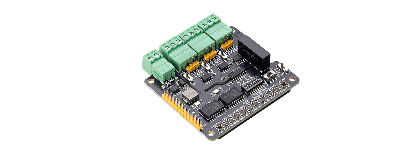
Overview
This product contains expansion circuit two CAN and one RS485 interface, and supports user-defined baud rate communication; onboard digital isolation chip and integrated isolation power supply can provide stable isolation signal and voltage, and the isolation terminal does not need additional power supply. TVS protection, high reliability, strong anti-interference, low power consumption. The product also provides a DC power input interface circuit, which can provide power for the module and the Raspberry Pi at the same time. We provide Raspberry Pi demo codes.
Product parameters
| Supply voltage | 5V |
| Logic voltage | 3.3V/5V |
| CAN Control chip | MCP2515 |
| CAN Transceiver | SN65HVD230DR |
| RS485 Transceiver | SP3485EN |
Dimensions | 65mm(L) x 56.5mm(H) |
| Weight | 25.5g |

Usage
Hardware Interface Configuration Instructions
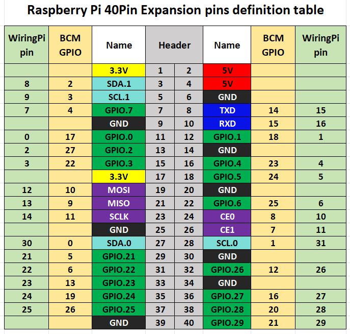
The level of the Raspberry Pi logic system is 3.3V. When using RS485-Dual-CAN-I, the user needs to pull the logic voltage slide switch in the lower right corner of the board to 3.3V. The sample program on the Raspberry Pi motherboard uses the pin definition of wiringPi number, and the wiring definition of the Raspberry Pi motherboard is shown in the following table:
| Function pin | Raspberry Pi interface(BCM) | Raspberry Pi Interface(WPI) | Describe |
|---|---|---|---|
| 5V | 5V | 5V | 5V Power positive |
| GND | GND | GND | Power ground |
| MISO | 9(MISO) | 13(MISO) | SPI_0 Data Output |
| MOSI | 10(MOSI) | 12(MOSI) | SPI_0 Data Input |
| SCLK | 11(SCLK) | 14(SCLK) | SPI_0 Clock Input |
| MISO-1 | 19 | 24 | SPI_1 Data Output |
| MOSI-1 | 20 | 28 | SPI_1 Data Input |
| SCLK-1 | 21 | 29 | SPI_1 Clock Input |
| CE0 | 8 | 10(P10) | CAN_0 Chip Select |
| 7 | 11(P11) | ||
| INT0 | 25 | 6(P6) | CAN_0 Interrupt Output |
| 13 | 23(P23) | ||
| CE1 | 17 | 0(P0) | CAN_1 Chip Select |
| 18 | 1(P1) | ||
| INT1 | 22 | 3(P3) | CAN_1 Interrupt Output |
| 24 | 5(P5) |
Module Resource Profile is shown in the figure below:
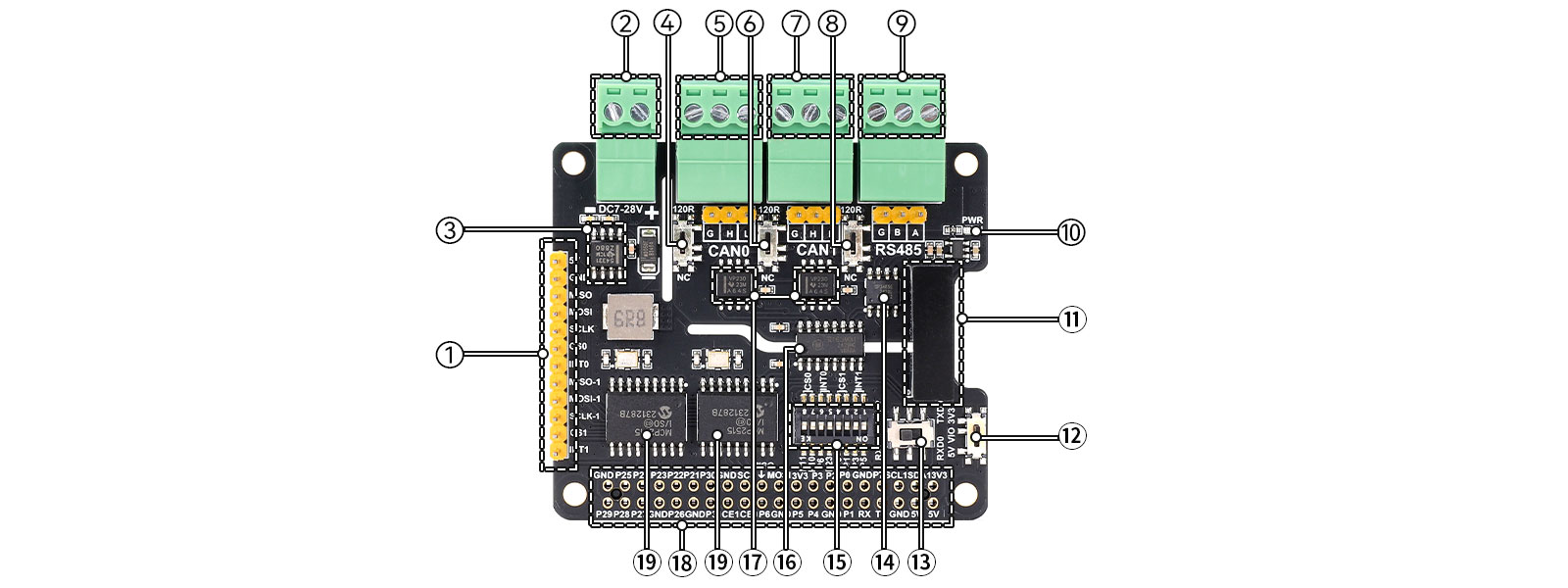
⒈ Leads to 2.54mm pin header control interface
⒉ External DC power input terminal
⒊ power chip TPS54331DR
⒋ Slide switch: CAN0 120 ohm resistance selection
⒌ CAN0 signal terminal
⒍ Slide switch: CAN1 120 ohm resistance selection
⒎ CAN1 signal terminal
⒏ Slide switch: RS485 120 ohm resistance selection
⒐ RS485 signal terminal block
⒑ DC5V isolated power module
⒒ Power Indicator
⒓ Slide switches: signal level selection
⒔ Slide switch: UART signal pin switching
⒕ SP3485E chip
⒖ 8-bit DIP switch: two groups of CAN chip selection and interrupt pin selection
⒗ Signal isolation chip π163M31
⒘ CAN transceiver chip SN65HVD230DR
⒙ Raspberry Pi 40Pin female socket
⒚ CAN bus controller chip MCP2515
Demo Codes Usage
Wiringpi Library Installation
sudo apt-get install wiringpi
wget https://project-downloads.drogon.net/wiringpi-latest.deb #Version 4B upgrade of Raspberry Pi
sudo dpkg -i wiringpi-latest.deb
gpio -v #
If version 2.52 appears, the installation is successful
For the Bullseye branch system, use the following command:
git clone https://github.com/WiringPi/WiringPi
cd WiringPi
./build
gpio -v
#Running gpio - v will result in version 2.70. If it does not appear, it indicates an installation error
If the error prompt "ImportError: No module named 'wiringpi'" appears when running the python version of the sample program, run the following command
#For Python 2. x version
pip install wiringpi#For Python 3. x version
pip3 install wiringpiNote: If the installation fails, you can try the following compilation and installation:
git clone --recursive https://github.com/WiringPi/WiringPi-Python.gitNote: The -- recursive option can automatically pull the submodule, otherwise you need to download it manually.
Enter the WiringPi Python folder you just downloaded, enter the following command, compile and install:
#For Python 2. x version
sudo python setup.py install#For Python version 3. X
sudo python3 setup.py installIf the following error occurs:

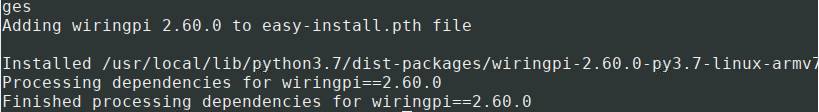
At this time, enter the command "sudo apt install swig" to install swig. After that, compile and install sudo python3 setup.py install. If a message similar to the following appears, the installation is successful.
Configure the serial port
sudo raspi-configsudo apt-get updatesudo systemctl stop [email protected]
sudo systemctl disable [email protected]The system defaults serial0 as the serial port in the console login mode. At this time, we need to cancel the console login function to avoid conflicts. Use the command "sudo nano /boot/cmdline.txt" to open the ".txt file"(For the Bookworm system, the file path is "/boot/firmware/cmdline.txt".), delete or comment in the opened file the following sentence.
console=serial0,115200
The programming conmmand is
sudo nano /boot/cmdline.txt #For the Bookworm system, the file path is "/boot/firmware/cmdline.txt".
Finally modify the content to
dwc_otg.lpm_enable=0 console=tty1 root=/dev/mmcblk0p2 rootfstype=ext4
elevator=dealine fsck.repari=yes rootwait
Open SPI Interface
sudo raspi-configEnable SPI interface:
Interfacing Options -> SPI -> Yes
To view enable SPI device:
ls /dev/spi* #
ls /dev/spi* #The following will be printed:"/dev/spidev0.0"and"/dev/spidev0.1"
Installation of Python Library
The demo codes uses the python 3 environment. To run the python demo codes, you need to install the spidev libraries. Enter the following commands in order to install:
sudo apt-get install python3-pip
sudo pip3 install spidev
System configuration instructions
The system configuration statement format of mcp2515 in /boot/config.txt (For the Bookworm system, the file path is "/boot/firmware/config.txt".)is:
dtoverlay=mcp2515,spiA-B,oscillator=16000000,interrupt=INT0
dtoverlay=mcp2515,spiC-D,oscillator=16000000,interrupt=INT1
Among them, the actual values of A, B, C, D, INT0, and INT1 are determined by the state of the 8-bit DIP switch, as shown in Table 2-2 below:
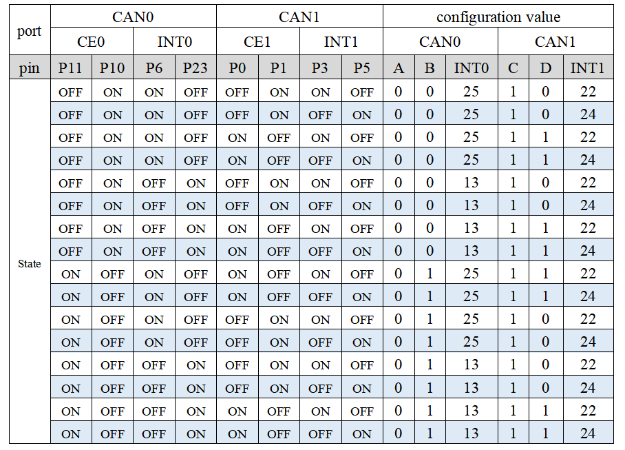
It can be seen from Table 2-2 that the value of INT0 and INT1 is the value of the BCM corresponding to its GPIO. When the CAN function is used normally, the states of the two GPIOs corresponding to each function pin are opposite. This is to ensure that Only one function pin is connected to the GPIO of the Raspberry Pi at the same time, for example, when the status of the DIP switch is shown in Table 2-3 below
| GPIO | P11 | P10 | P6 | P23 | P0 | P1 | P3 | P5 |
|---|---|---|---|---|---|---|---|---|
| State | ON | OFF | ON | OFF | ON | OFF | OFF | ON |
After comparing with Table 2-2, the statement configured in /boot/config.txt (For the Bookworm system, the file path is "/boot/firmware/config.txt".)at this time
dtoverlay=mcp2515,spi0-1,oscillator=16000000,interrupt=25
dtoverlay=mcp2515,spi1-1,oscillator=16000000,interrupt=24
The RS485 bus uses two sets of UARTs for users to switch, namely the "mini serial port" /dev/ttyS0 (corresponding to TXD0 and RXD0) and the hardware serial port /dev/ttyAMA1 (corresponding to TXD2 and RXD2), of which /dev/ttyS0 has low performance , the function is also simple, and there is no dedicated clock source for the baud rate but is provided by the CPU core clock, so the weakness of the "mini serial port" is: the baud rate is affected by the core clock, if the core intelligently adjusts the power consumption to reduce the main frequency , the corresponding baud rate of the mini serial port will be implicated. And /dev/ttyAMA1 has a separate baud rate clock source, with high performance and reliability. When users enable /dev/ttyAMA1, they need to add the "dtoverlay=uart2" statement (for RPi 5 it should be "dtoverlay=uart1-pi5",or for bookworm sysytem it should be "dtoverlay=uart1" )in a single line in the config.txt file.
If users need serial port 0 (TXD0 and RXD0) to have the same performance as serial port 2, they need to add the "dtoverlay=pi3-disable-bt" statement in a single line in the config.txt file. After restarting, "/dev/ttyS0" is swapped with "/dev/ttyAMA0", and the serial port 0 (TXD0 and RXD0) device symbol becomes /dev/ttyAMA0, which has the same high performance as serial port 2.
After testing, when the serial port 0 (TXD0 and RXD0) uses ttyS0, the baud rate range can only reach 1200~921600bps, while when using ttyAMA0, the range can reach 200~921600bps.
Demo codes
1)When the module leaves the factory, the status of the DIP switch is set as follows:
| GPIO | P11 | P10 | P6 | P23 | P0 | P1 | P3 | P5 |
|---|---|---|---|---|---|---|---|---|
| State | ON | OFF | ON | OFF | ON | OFF | OFF | ON |
Run the command "sudo nano /boot/config.txt" to open the .txt file(For the Bookworm system, the file path is "/boot/firmware/config.txt".), and add the following content (if you need to switch to other states, please refer to Table 2-2 in Chapter 2.2.5 System Configuration Instructions):
dtoverlay=spi1-3cs
dtoverlay=mcp2515,spi0-1,oscillator=16000000,interrupt=25
dtoverlay=mcp2515,spi1-1,oscillator=16000000,interrupt=24
dtoverlay=uart2 #for RPi 5 it should be"dtoverlay=uart1-pi5"
2) Run the demo codes to restart the Raspberry Pi
sudo reboot3) Run the demo codes
dmesg | grep spiIf the following information appears, it means that the initialization has been successful:

If the above information does not appear, you need to check whether the DIP switch setting of the module matches the content added in the /boot/config.txt file(For the Bookworm system, the file path is "/boot/firmware/config.txt".).
4) Enter the following command to start can
sudo ip link set can0 up type can bitrate 1000000
sudo ip link set can1 up type can bitrate 1000000
5) Enter the ifconfig command to view:
can0:flags=193<UP,RUNNING,NOARP> mtu 16
...........................
can1:flags=193<UP,RUNNING,NOARP> mtu 16
...........................
6) Connect H---->H;L---->L of the two CAN interfaces on the board
7) Install the can-utils tool:
sudo apt-get install can-utils8) can test:
Open two terminal windows and enter the following command on one port to receive data from can0:
candump can0
Another terminal enters the following command for sending data:
cansend can1 123#00.11.22.33.44.55.66
If the H and L signals of the two CAN connections on the board are not connected separately, the terminal of the candump command cannot receive data, and the command is modified in the corresponding terminal to:
candump can1
candump can0 123#11.22.33.44.55.66
Check whether the data is sent and received correctly.
9) Connect the USB to RS485 module to the computer, open the serial port debugging assistant on the computer side, select the device number of the USB to RS485 module as the serial port number, and connect the board RS485 terminal (⑨ in 2-1 resource introduction diagram) and the USB to RS485 module The wiring is:
A-->A
B-->B
GND-->GND
Open the send.py and receive.py files located in the demo codes folder (download link available in Resource -> Demo Codes below) using the Thonny Python IDE software on the Raspberry Pi system, and modify the content of the following statement according to different baud rates and serial devices: ser = serial. Serial("/dev/ttyAMA0",921600,timeout=0.2)
The first parameter in the above Serial function is the symbol of the selected serial port device. When the serial port signal selection switch (see○13in the 2-1 resource profile diagram) is turned to the left (TXD2, RXD2), the parameter is "/dev /ttyAMA1", when the serial port signal selection switch is turned to the right (TXD0, RXD0), then the parameter is "/dev/ttyS0" or "/dev/ttyAMA0", the corresponding settings can refer to the above 2.2.4 system configuration Describes the content of the chapter.
Resources
Data Sheet