Overview
This product uses an I2C interface to provide 16-channel I/O port expansion.It supports Raspberry Pi Zero / Zero W / Zero WH / 2B / 3B / 3B+ / 4B, and also supports Raspberry Pi Pico, Arduino, and STM32.We provide C and Python demo codes for Raspberry Pi, as well as demo codes for Raspberry Pi Pico, Arduino, and STM32, which can be used to perform input testing, output testing, and interrupt testing
Product Parameters
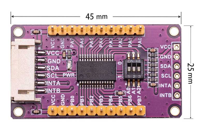
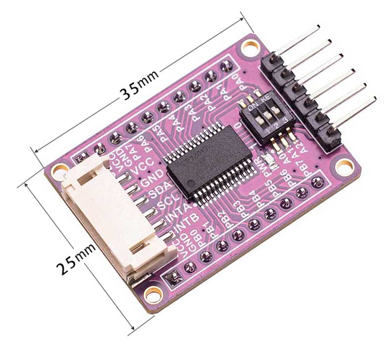
| Model | SG IO E017 | SG IO E017 A |
|---|---|---|
| Dimensions | 45mm(Length) x 25mm(Width) | 35mm(Length) x 25mm(width) |
| Control Chip | MCP23017 | MCP23017 |
| Communication Interfaces | I2C | I2C |
| Supply Voltage | 3.3V/5V | 3.3V/5V |
| Expansion I/O | 16 | 16 |
| Interrupt Pin | INTA、INTB | INTA、INTB |
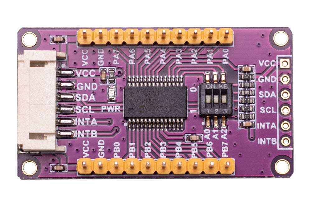
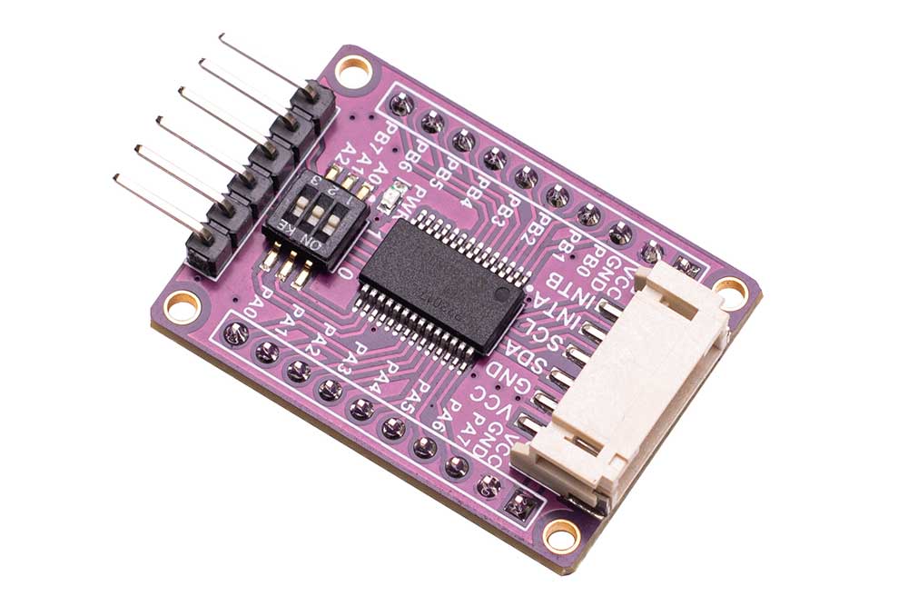
The resource profile diagram is shown in the figure below:
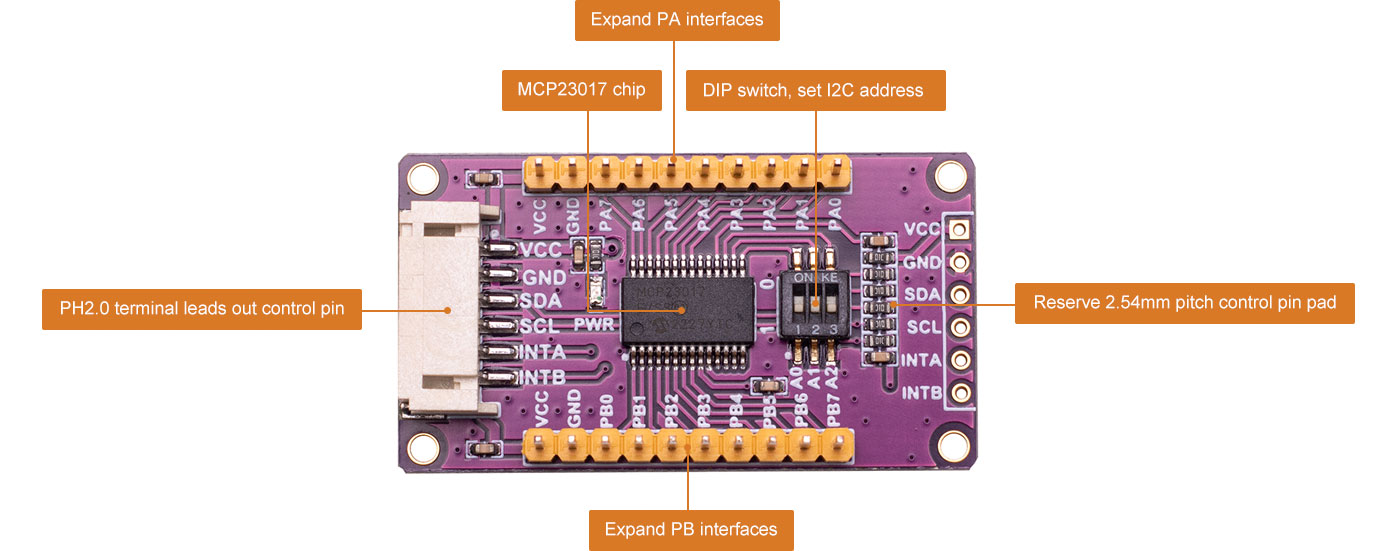
Resource Definition
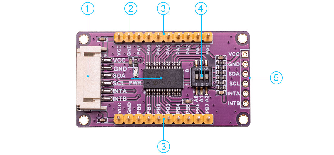
① PH2.0 connector leads out control pin
② MCP23017 chip
③ Expand PA and PB ports
④ DIP switch, set I2C address
⑤ Reserve 2.54mm pitch control pin
Usage
This module demo codes sets the PA port (PA0~PA7) as the output and cycles the high and low levels at an interval of 1 second. The PB port (PB0~PB7) is set as the input. In addition, it is configured that when the level of any pin of the PB port changes, an interrupt is generated through the INTB pin. At this time, the level of the PB port is read.
Raspberry Pi Demo Codes Usage
Since the bookworm system no longer supports the wiringpi library, the example program for this system uses the lgpio library, and for the bullseye system, the wiringpi library version of the example program can be used.
Hardware Interface Configuration Description
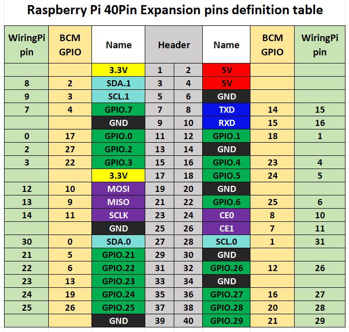
The demo codes in the Raspberry Pi motherboard adopts the pin definitions number by wiringPi, and the bookworm system uses the pin definition of the BCM number.
The module with Raspberry Pi motherboard wiring is defined in the following table:
| Pin | Pin Function | Raspberry Pi |
|---|---|---|
| VCC | Power supply positive(3.3V/5V) | 3.3V |
| GND | Power supply ground | GND |
| SDA | I2C data line | SDA1 |
| SCL | I2C clock line | SCL1 |
| INTA | PA port interrupt pin | P0(wiringpi number) |
| INTB | PB port interrupt pin | P1(wiringpi number) |
Demo Codes Usage
Wiringpi Library Installation
First, use the "gpio -v" command on the terminal to check whether the wiringpi library has been installed. If the information of 2.52 appears, it means that the installation has been successful. You can skip this part of the content, otherwise you need to install it as follows:
sudo apt-get install wiringpi#For Raspberry Pi systems after May 2019 (earlier ones do not need to be executed), an upgrade may be required:
wget https://project-downloads.drogon.net/wiringpi-latest.deb
#Version 4B upgrade of Raspberry Pi,If your download fails or the #speed is very slow, you can download it at the following linkand then #and copy it to the Raspberry Pi motherboard:
#https://github.com/seengreat/wiringpi-library
Version 4B upgrade of Raspberry Pi
sudo dpkg -i wiringpi-latest.deb
gpio -v
If version 2.52 appears, the installation is successful
#For the Bullseye branch system, use the following command:
git clone https://github.com/WiringPi/WiringPi
cd WiringPi
./build
gpio -v
#Running gpio - v will result in version 2.70. If it does not appear, it indicates an installation error
If the error prompt "ImportError: No module named 'wiringpi'" appears when running the python version of the sample program, run the following command
#For Python 2. x version
pip install wiringpi#For Python3. x version
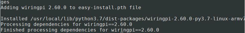
pip3 install wiringpiNote: If the installation fails, you can try the following compilation and installation:
git clone --recursive https://github.com/WiringPi/WiringPi-Python.gitNote: The -- recursive option can automatically pull the submodule, otherwise you need to download it manually.
Enter the WiringPi Python folder you just downloaded, enter the following command, compile and install:
#For Python 2. x version
sudo python setup.py install#For Python 3. x version
sudo python3 setup.py installIf the following error occurs:

At this time, enter the command sudo apt install swig to install swig. After that, compile and install sudo python3 setup.py install. If a message similar to the following appears, the installation is successful.
Lgpio library installation
For the bookworm system, the sample program uses the lgpio library. The following is the installation command for the library:
wget https://github.com/joan2937/lg/archive/master.zip
unzip master.zip
cd lg-master
make
sudo make install
Open I2C interface
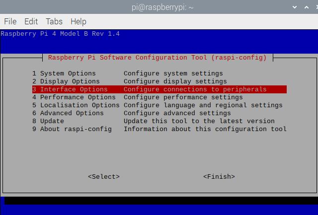
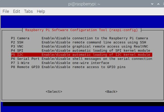
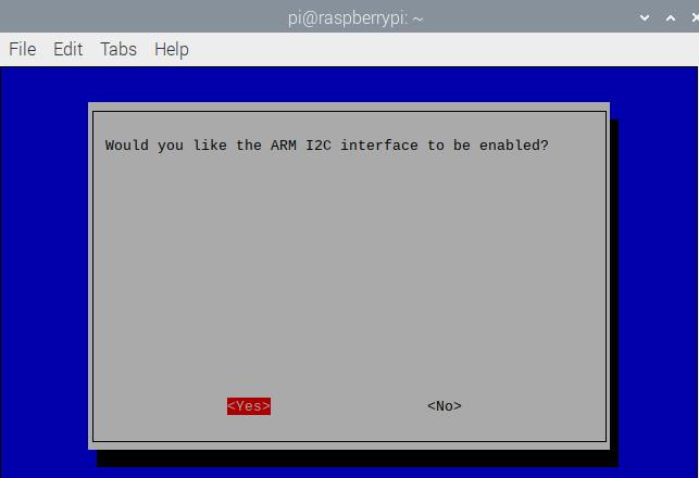
sudo raspi-configEnable I2C interface:
Interfacing Options -> I2C -> Yes
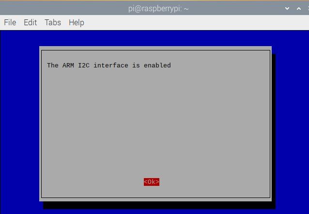
Restart the device.
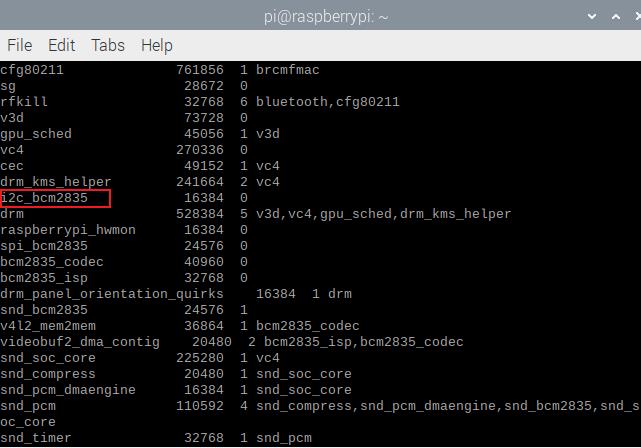
sudo rebootRun the command to check whether I2C is started.
lsmodIf i2c_bcm2835 are displayed, it means I2C module is started.
Install the i2c-tools tool to confirm
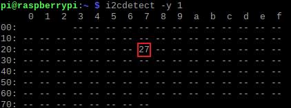
sudo apt-get install i2c-toolsView connected I2C devices
i2cdetect -y 1Check the address, as shown in the figure, it indicates that the I/O expansion board is successfully connected to the Raspberry Pi, and the DIP switch is connected to the high level by default, and the displayed address is 0X27;
Installation of Python libraries
The demo codes uses the python 3 environment. To run the python example program, you need to install smbus:
sudo apt-get install -y python-smbusC Demo Codes
Open the demo codes/raspberry_pi/c directory
sudo make clean
sudo make
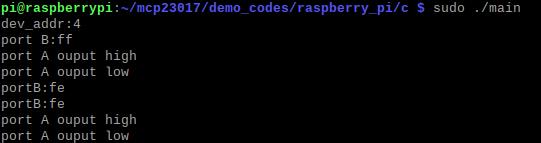
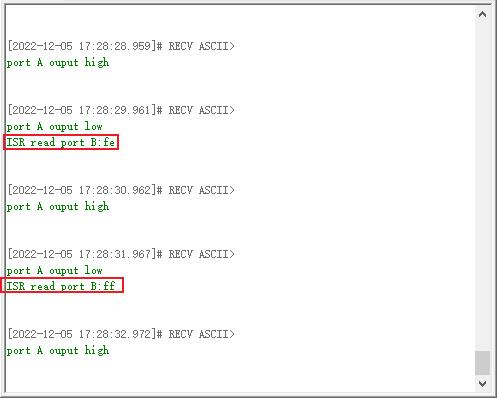
sudo ./mainConnect the expansion board according to the demo codes description. After running the program, the output result of the Raspberry Pi terminal is as follows:; "Port B: ff" means that all the input pins of the PB port of the module are high by default (0xff: 1111111); "Port A" refers to PA0~PA7 pins, "port A output high" refers to all PA port pins outputting high level, "port A output low" refers to all PA port pins outputting low level, and the module PA port output pins cyclically switch high and low levels at an interval of 1 second. Users can also connect PA0~PA7 to LEDs, and it can be observed that LEDs are flashing constantly. At this time, the output test is normal;
Connect the PB0 port to the GND with a jumper, and then trigger the interrupt on the INTB pin. The Raspberry Pi terminal outputs "portB: fe", that is, the input level of the PB port changes from the original 0xff (11111111) to 0xfe (11111110).
Python Demo Codes
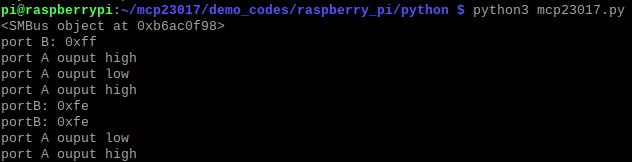
Open the demo codes\raspberry_pi\python directory
python3 mcp23017.pyThe demo codes of Python version is similar to that of C language. The running result is shown in the following figure:The demo
Arduino Demo Codes Usage
Wiring Instructions
| SG-IO-E017 | Pin Function | Arduino |
|---|---|---|
| VCC | Power supply positive(3.3V/5V) | 5V |
| GND | Power supply ground | GND |
| SDA | I2C data line | SDA |
| SCL | I2C clock line | SCL |
| INTA | PA port interrupt pin | D2 |
| INTB | PB port interrupt pin | D3 |
Demo Codes Usage
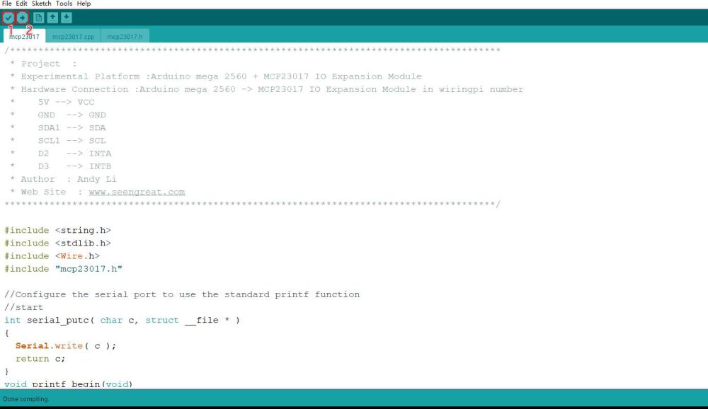
Open the project file demo codes\Arduino\mcp23017\mcp23017.ino with the Arduino IDE, click Verify, and upload it to the development board after verification.
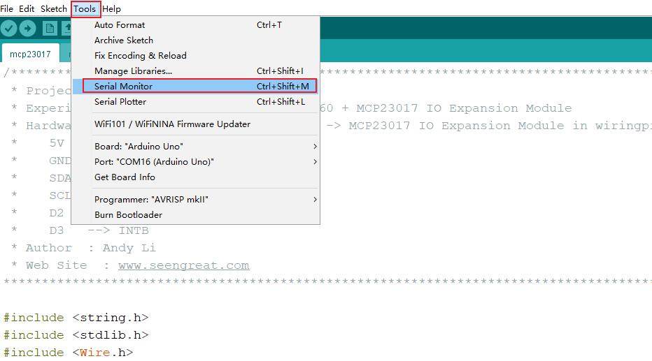
Click the tool, open the serial port monitor, set the baud rate to 115200, and observe the data changes.
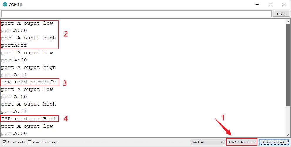
Open the serial port monitor and the display is as follows. Set the baud rate to 115200 (as shown in "1" in the figure below). The program running results are shown in the figure below:
STM32 Demo Codes Usage
Wiring Instructions
| SG-IO-E017 | Pin Function | STM32 |
|---|---|---|
| VCC | Power supply positive(3.3V/5V) | 3.3V |
| GND | Power supply ground | GND |
| SDA | I2C data line | PB11 |
| SCL | I2C clock line | PB10 |
| INTA | PA port interrupt pin | PB3 |
| INTB | PB port interrupt pin | PB4 |
Demo Codes Usage
Open the main. Uvprojx project file in the directory demo codes\STM32\USER with Keil_Vision5 software, and connect the module with STM32 according to the above table; The program is downloaded to the STM32 development board after being compiled without errors;
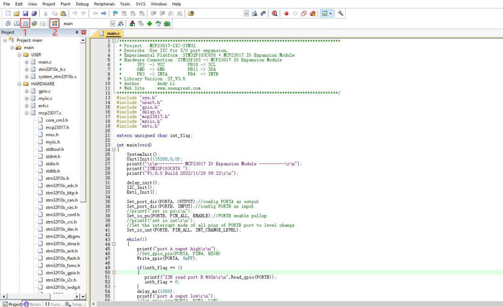
The debugging information output serial port in the demo codes is USART1, where PA9 is Tx and PA10 is Rx; After connecting the cable, open the Serial Port Debugging Assistant, select the serial port number, adjust the baud rate to 115200, click "Open", and the Serial Port Debugging Assistant window is shown as follows:
Resources
Schematic
Data Sheet