Overview
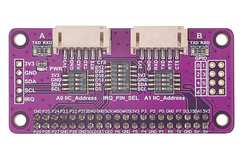
Based on Raspberry Pi 40P connector design, suitable for Raspberry Pi Zero/ Zero W/ Zero WH/ 2B/ 3B/ 3B+/ 4B/ 5, using SC16IS752 chip solution, it can expand two serial ports and 8 GPIOs at the same time. The settings of I2C address and the selection of interrupt pins are designed with DIP switch, convenient for users to set.
Specifications
- Supply voltage: 3.3V or 5V
- Logic Voltage:3.3V
- PWM Driver Chip:SC16IS752
- Interface Protocol:I2C
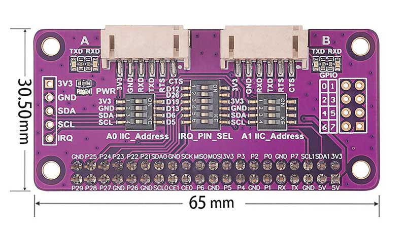
- Size: 65mm(length) x 30.5mm(width)
Interface Resources
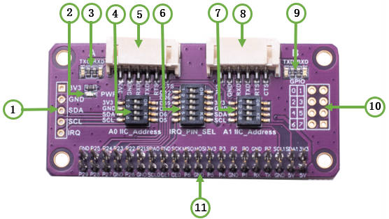
- 1. I2C control lead out interface
- 2. Board power indicator
- 3. Serial port A data receiving and transmitting indicator
- 4. I2C Address A0 setting
- 5. Serial port A connector
- 6. Interrupt pin selection
- 7. I2C Address A1 setting
- 8. Serial port B connector
- 9. Serial port B data receiving and transmitting indicator
- 10. GPIO connector
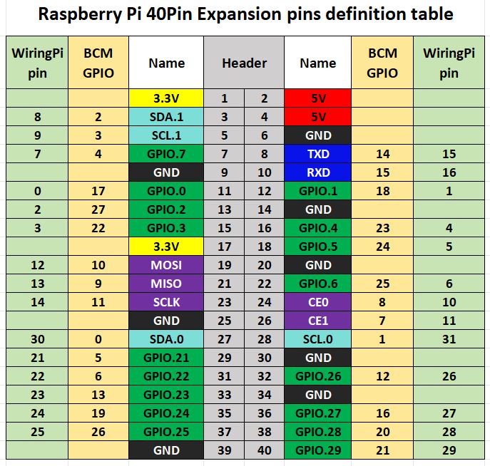
- 11. Raspberry Pi 40P female connector
Serial port A/B connector pin description:
| Pin mark | Pin Description |
| CTSA/B | Serial port A/B Clear To Send |
| RTSA/B | Serial port A/B Require To Send |
| TXDA/B | Serial port A/B Transmitted Data |
| RXDA/B | Serial port A/B Received Data |
| GND | GND |
| 3.3V | 3.3V Power |
Usage
Instructions of Hardware Interface Configuration
The Serial Expansion Module leads out all the I2C address lines, and can set the addresses of A0 and A1 through the DIP switch. In addition, there are 6 interrupt pins, which can stack up to 6 Serial Expansion Modules. The demo codes we provide is to set the address to 0x48, setting the interrupt pin to P5 (BCM).
The corresponding relationship between A0 and A1 setting addresses is as follows:
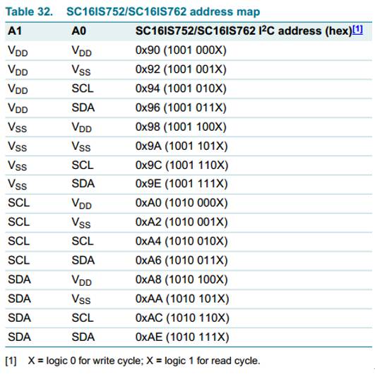
It can be seen that the addresses listed in the table are all 8-bit data, and the I2C address in actual operation is 7-bit, so it needs to be shifted one bit lower. For example, if the first A1 and A0 are connected to VDD, the address given in the table is 0x90 (1001 000X), but in actual use, the corresponding device address should be, 100 1000, that is, 0x48. If you need to stack Serial Expansion Modules, you need to set the stacked Serial Expansion Modules to other addresses and other interrupt pins.
Demo Codes
Since the bookworm system no longer supports the wiringpi library, the example program for this system uses the lgpio library, and for the bullseye system, the wiringpi library version of the example program can be used.
Install wiringpi library:
sudo apt-get install wiringpi
wget https://project-downloads.drogon.net/wiringpi-latest.deb #Raspberry Pi 4B version upgrade
sudo dpkg -i wiringpi-latest.deb
gpio -v #
If version 2.52 appears, it means that the installation has been successful
Install lgpio library:
For the bookworm system, the sample program uses the lgpio library. The following is the installation command for the library:
wget https://github.com/joan2937/lg/archive/master.zip
unzip master.zip
cd lg-master
make
sudo make install
Generate device:
sudo nano /boot/config.txt #/boot/firmware/config.txt for bookworm system
# addr is set according to the actual combination of A0 A1 jumper caps, the default is 0x48
dtoverlay=sc16is752-i2c,int_pin=5,addr=0x48# If you need to stack multiple Serial Expansion Modules, modify x and 0xyy in the following code according to the combination of your actual jumper caps, and remove #
#dtoverlay=sc16is752-i2c,int_pin=x,addr=0xyy# Reboot the device
sudo rebootExecute after restart:ls /dev/ttySC*
If /dev/ttySC0 and /dev/ttySC1 appear, the configuration is successful; if two Serial Expansion Modules are stacked, /dev/ttySC0, /dev/ttySC1, /dev/ttySC2, /dev/ttySC3 will appear.
Install the serial library in the python environment:
sudo apt-get install python3-serial1、Raspberry Pi I2C Configuration
Start the Raspberry Pi system configuration:
sudo raspi-configEnable I2C interface:
Interfacing Options -> I2C -> Yes
Reboot the device
sudo rebootCheck out the enabled I2C devices:
ls /dev/i2c* #will print out:"/dev/i2c-1"
Install the I2C library:
sudo apt install i2c-toolsInstall python's smbus:
sudo apt install python-smbusDetect the address of the device mounted on the I2C bus:
sudo i2cdetect -y -a 12、Execute the I2C interface sample program
Python:
For the bookworm system, if you are using a Raspberry pi 4B, you will need to change PIN_NUM_START = 625 to PIN_NUM_START = 578.
Enter the python directory:
cd /home/pi/Serial_Expansion_Module/demo_codes/raspberry_p/pythonRun:
sudo python3 sc16is752.pyC:
For the bookworm system, if you are using a Raspberry pi 4B, change #define PIN_START 625 to #define PIN_START 578 in sc16is752.h.
Enter the c directory:
cd /home/pi/Serial_Expansion_Module/demo_codes/raspberry_pi/cExecute:
make clean
make
sudo ./main
3、Demonstration codes description
Wiring Instructions:
TXDA----RXDB
RXDA----TXDB
The demo codes is for the operation when only one Serial Expansion Module is inserted. First, complete the initialization of the serial port and GPIO, configure GPIO0~GPIO3 as outputs, and configure GPIO4~GPIO7 as inputs, and then enter the loop steps with a cycle of about 1 second: ttySC0 sends the character "Hello word", ttySC1 sends the character "www.seengreat.com", then reads the content of the characters received by ttySC0 and ttySC1 and prints it, then GPIO0~GPIO3 output the out_val level and read the input level of GPIO4~GPIO7 , the value of out_val is reversed once in each loop.
The serial device symbols are /dev/ttySC0 and /dev/ttySC1, GPIO is controlled by sysfs. For non-bookworm systems, it will generate gpiochip496 in the /sys/class/gpio file path, and GPIO0~GPIO7 on the module correspond to gpio496~gpio503.If two Serial Expansion Module are stacked, gpiochip488 will be added under the /sys/class/gpio file path, and GPIO0~GPIO7 on the second module correspond to gpio488~gpio495. For the Raspberry pi 5 on the bookworm system, it will generate gpiochip625 in the /sys/class/gpio file path, and GPIO0~GPIO7 on the module corresponds to gpio625 ~gpio632. At the same time, users need to modify the demo codes to use the GPIO pins of the second module.
Resources
Demo Codes for bullseye system
Demo Codes for bookworm system
Data Sheet