I Product Overview
5V-24V Solar Panel, with MPPT, DC-044 Power Jack and KF128L-2P Terminal Block
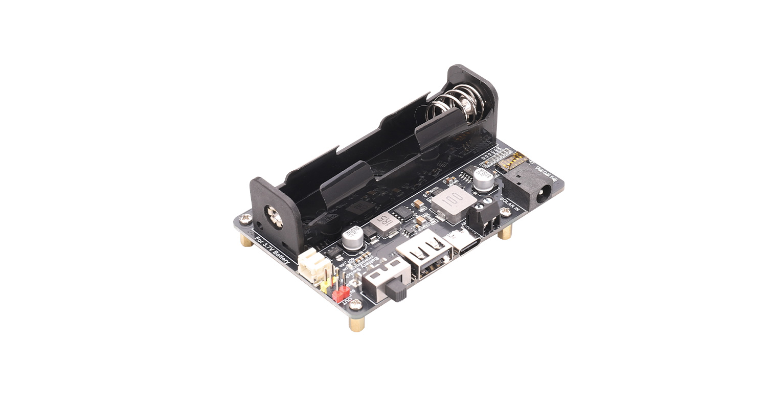
Solar Energy Manager is a solar power management module, which can charge the 3.7V 18650 lithium battery through solar panel or USB port.The module features MPPT (Maximum Power Point Tracking) and protection functions of battery charging and discharging. MPPT power point tracking can automatically adjust the charging power according to the input voltage, taking advantage of solar energy more efficiently. The protection circuit of charging and discharging can monitor the battery voltage in real time, preventing the battery from overcharging and over-discharging. It can protect the battery and prolong the battery life. Due to its excellent stability and efficient management of charging and discharging, it can be used in solar power generation, low-power IoT and other environmental protection projects.
II Features
Supports MPPT (Maximum Power Point Tracking) function, maximizing the efficiency of the solar panel
- Supports solar panel / power adapter/USB multiple methods of connections for battery charging
- Suitable for 5V-24V solar panel, being wiring through DC-044 power jack or terminal block
- On-board MPPT SET switch, select the level closed to input level to improve charging efficiency
- On-board two ways of 5V output connectors:One USB female socket and two sets of pin headers, convenient for users
- Lead out the battery charging status and battery power pins (the pin header is not soldered)
- On-board 18650 battery holder and PH-2P battery socket, convenient to connect multi kinds of 3.7V rechargeable Li battery or Li battery pack
- Onboard various status indicators for checking the status of solar panel and battery easily
- Mounting holes are compatible with Raspberry Pi 3/4/5 series motherboards
- The board supports simultaneous charging and discharging
- Multi protection circuits: over charge / over discharge / reverse protection / over current, stable and safe to use
III Specifications
Solar Panel Input Voltage | 5-24V |
USB TYPE-C Input Voltage | 5V |
USB Output | 5V/2A |
Maximum solar charging power | about 9.5W |
Pin Header Output | 5V/2A and 3.3V/1A |
Charging Cutoff Voltage | 4.2V ±1% |
Over Discharging Protection Voltage | 2.9V ±1% |
Charging Efficiency | About 78% |
Output Efficiency of Battery | Max 94% |
Max Quiescent Current | <4mA |
Operating Temperature | -40℃~85℃ |
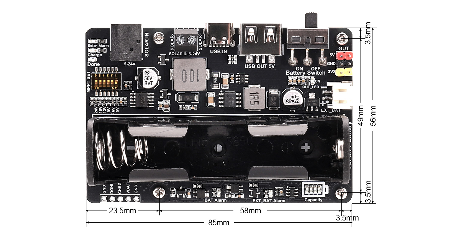
Dimensions | 85mm(Length)*56mm(Width) |
IV Usage
4.1 Instructions of Hardware Connectors Configuration
The hardware connectors of the Solar Energy Manager module as following:
1. Two input connectors for solar panel: A DC-044 power jack and a KF128L-3.5-2P terminal block. According to the output connectors of the solar panel, the users can select both of one to connect to the Solar Energy Manager module. The input voltage is 5-24V. After wiring to the solar panel, select the corresponding MPPT voltage according to the output voltage of the solar panel.
2. One USB TYPE-C input port: The battery can be charged through the USB TYPE-C port. When selecting USB TYPE-C to charge the battery, please disconnect the solar panel, and then set the MPPT voltage to the output voltage of the power adapter through the dial switch MPPT SET.
3. One 18650 battery holder:When putting the 18650 Li battery, please pay attention to the positive and negative poles of the battery, and do not reverse the positive and negative poles of the battery. The module features reverse protection of the battery connection and reverse alarm. If the indicator of the battery alarm is always on after putting the battery, it means that the positive and negative poles of the battery are reversed, therefore, the battery should be re-installed correctly immediately.
4. One PH-2PWB expansion connector for battery: The 3.7V Li battery and Li battery pack with higher capacity can be expanded through the PH-2PWB expansion connector.
5. Please pay attention to the positive and negative poles of the expansion connector, and it is forbidden to connect the positive and negative poles reversely and short-circuit them.
6. Power output port: The maximum total output power of the power supply is 10W. It consists of a USB female socket and two sets of 2.54mm pitch pin headers. The USB socket provides 5V output, and the 2.54mm pitch pin header provides 5V and 3.3V output. Both Together they can output a maximum power of 10W, of which the maximum current of the 3.3V power supply is 1A.
7. Charging status indication and battery power output pins (2.54mm pitch unsoldered pin header, see⑲ in Figure 4-1): "DONE" and "CHRG" pins are charging status indication pins, active at low level, respectively by connecting the negative pole of the "Charge" and "Done" indicators, the user can connect to the MCU system to automatically query the battery charging status.
8. Battery power output pins "VBAT" , where "VBAT" is the positive terminal of the battery, the voltage between "VBAT" and "GND" is the battery voltage, and this voltage range is 2.9~4.2V. It is valid when the battery switch "Battery Switch" is turned to "ON". The user can connect this voltage to the ADC system through these two pins to query the battery capacity.
4.2 Resource Profile
Notice:
●When putting the Li battery, and wiring to solar panel, please pay attention to the positive and negative poles of the battery, and do not reverse.
●Do not directly touch the core components with both hands while the product is operating, and do a good job of electrostatic protection.
●When supplying power to the load through the output of pin headers, please pay attention to the positive and negative poles, do not connect them in reverse.
Module Resource Profile is shown in the figure below:
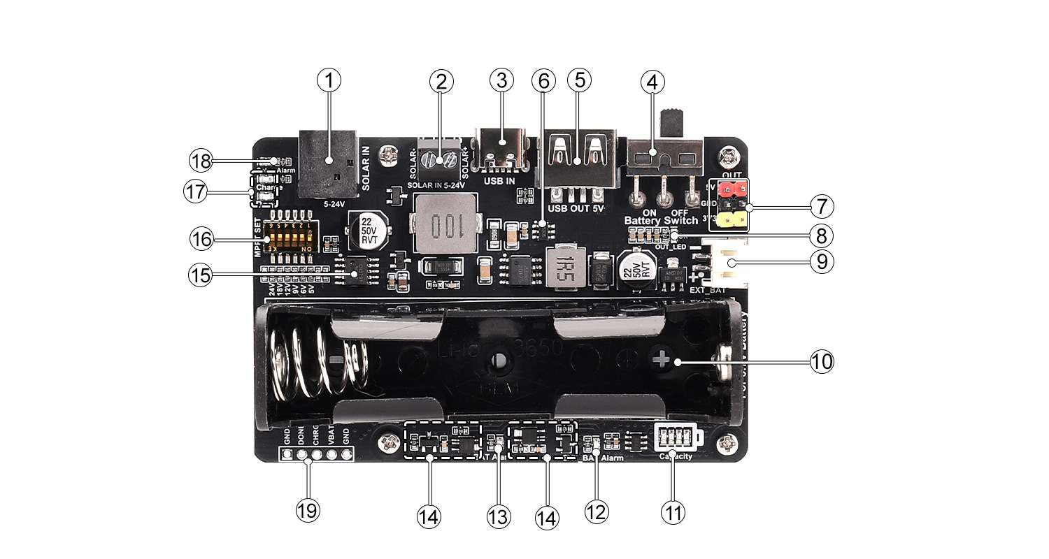
Figure 4-2 Overview of Resources for Version V4.0 or Later
①Solar charging connector: can be wired to the solar panel through the DC-044 power jack.
②Solar charging connector: can be wired to the solar panel through the terminal.
③USB charging connector: can use the power adapter to charge the battery through the TYPE-C data cable.
④The switch of Battery,This switch should be turned to "ON" when charging the battery and outputs 5V and 3.3V.
⑤USB output port: output 5V/2A power through the USB port.
⑥Output boost chip: CN5305 boost chip.
⑦Pin header output port: output 5V/2A and 3.3V/1A power through pin header of 2.54mm pitch.
⑧Output status indicator.
⑨3.7V lithium battery expansion connector: 3.7V lithium battery can be expanded through the PH-2PWB connector, and the expanded lithium battery can be charged and discharged.
⑩18650 lithium battery holder.
⑪The indicator of battery capacity.
⑫Battery Output Activation Button (for Version V3.9 or Earlier) :After installing the battery correctly, toggle the Battery Switch to the ON position. If the OUTPUT ON indicator LED fails to illuminate, press this button once at this time.
External battery (see ⑨ in Figure 4-2 for Version V4.0 or Later) reverse connection warning indicator: lights up to issue a warning when the battery is reversely connected.
⑬The warning indicator for battery reverse connection : lights up to warn when the battery is reversely connected.
⑭Lithium battery protection circuit: lithium battery overcurrent, overdischarge, overcharge protection circuit.
⑮ CN3791 solar charging chip.
⑯ DIP switch for setting MPPT voltage : Solar charging MPPT voltage setting DIP switch, set the MPPT voltage according to the charging voltage, which can improve the charging efficiency. The MPPT setting voltage should be less than or equal to the input voltage. The solar panel input and USB TYPE-C input cannot charge the battery at the same time, only one port can be selected to charge the lithium battery at any time.
⑰Lithium battery charging indicator: Charge: the light is on when the lithium battery is charged through the solar panel or USB connector; Done: the light is on when the lithium battery is charged (Done flashes when the lithium battery is disconnected or not connected during the charging process).
⑱Warning indicator for solar panel reverse connection: When the solar panel is wired to the Solar Energy Manager, if the positive and negative poles are reversed, the warning indicator will light up to give an alarm.
⑲ Lead out the battery charging status and battery power pins (the pin header is not soldered).
4.3 Related instructions
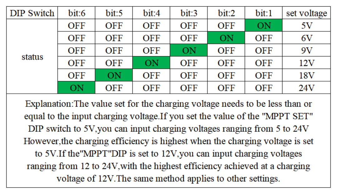
1. "MPPT SET" DIP switch setting: Only one of the bits can be set to "ON" and the other bits to "OFF". The voltage set by the "MPPT SET" DIP switch is set according to the specifications of the solar panel. The closer the no-load output voltage of the solar panel is to the voltage set by the MPPT, the higher the charging efficiency will be, the premise is that the voltage output by the solar panel must be greater than or equal to the voltage set by the MPPT.The charging voltage settings are shown in the diagram below:
2. About battery charging power: the lower the battery power, the greater the charging power; the higher the solar panel output power, the greater the charging power; when the solar panel output power is sufficient and the battery power is low, its maximum charging power is about 9.5W.
Ⅴ Appendixes
5.1 Precautions
- Do not plug or unplug modules while they are powered on.
- Follow all warnings and guidelines provided on the product.
- Keep the product dry. In case of accidental splashing or immersion in any liquid, immediately disconnect the power and thoroughly dry the product.
- Ensure proper ventilation and heat dissipation in the operating environment to avoid damage to components due to high temperatures.
- Do not use or store the product in dusty or dirty environments.
- Avoid using the product in environments with frequent temperature changes to prevent condensation damage to the components.
- Handle the product gently, as dropping, hitting, or severe shaking may damage the circuits and components.
- Do not clean the product with organic solvents or corrosive liquids.
- Do not attempt to repair or dismantle the product by yourself. In case of any malfunction, please contact our company for repairs. Unauthorized repairs may damage the product, and any resulting damage will not be covered under warranty.
Resources
Data Sheet