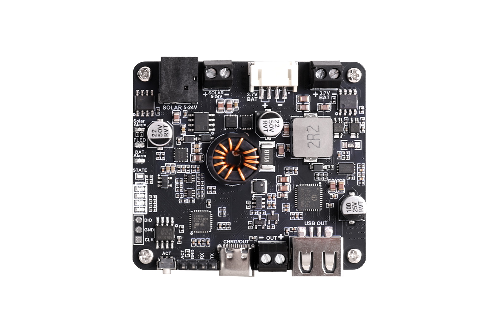
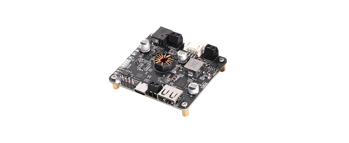
 I. Product Overview
Solar Energy Manager F is a multifunctional power management module designed for solar-powered, portable energy storage, and embedded device applications. The module uses CN3881 as the solar charging management core, supports MPPT maximum power point tracking, and performs step-down charging for single-cell Li-ion/Li-polymer batteries.
An onboard STM32 MCU manages the system and enables automatic MPPT voltage adjustment without DIP switch settings.
The module also integrates the IP5356M fast-charging power management IC, providing USB Type-C bidirectional charging/discharging, USB-A output, and 3.5 mm terminal block output. It supports USB PD, QC, FCP, AFC, and other fast-charging protocols. The IP5356M itself supports up to 22.5 W boost output, with USB-C PD supporting 5 V, 9 V, and 12 V voltage levels.
On the battery side, the CW2217 fuel gauge IC measures battery voltage, current, and SOC in real time. An AT24C32 external EEPROM is provided to save system configuration, calibration parameters, or operating data. In addition, the module includes single-cell lithium battery protection circuitry, providing overcharge, over-discharge, overcurrent, and short-circuit protection.
This module is suitable for solar-powered terminals, portable energy storage, outdoor electronic devices, IoT nodes, backup power, and solar USB charging devices.
II. Features
- Approx. 20 W solar charging power with high conversion efficiency
- Supports automatic MPPT power point adjustment; no user setup required
- Supports multiple charging methods: solar panel / power adapter / USB
- Suitable for solar panels with output voltage of 5–24 V; connect via DC-044 power jack or terminal block
- More accurate battery monitoring using the CW2217 fuel gauge; monitors battery voltage, charge/discharge current, and SOC
- Onboard 3.5 mm terminal block, USB-A, and USB-C output interfaces; the Type-C port supports fast-charging output
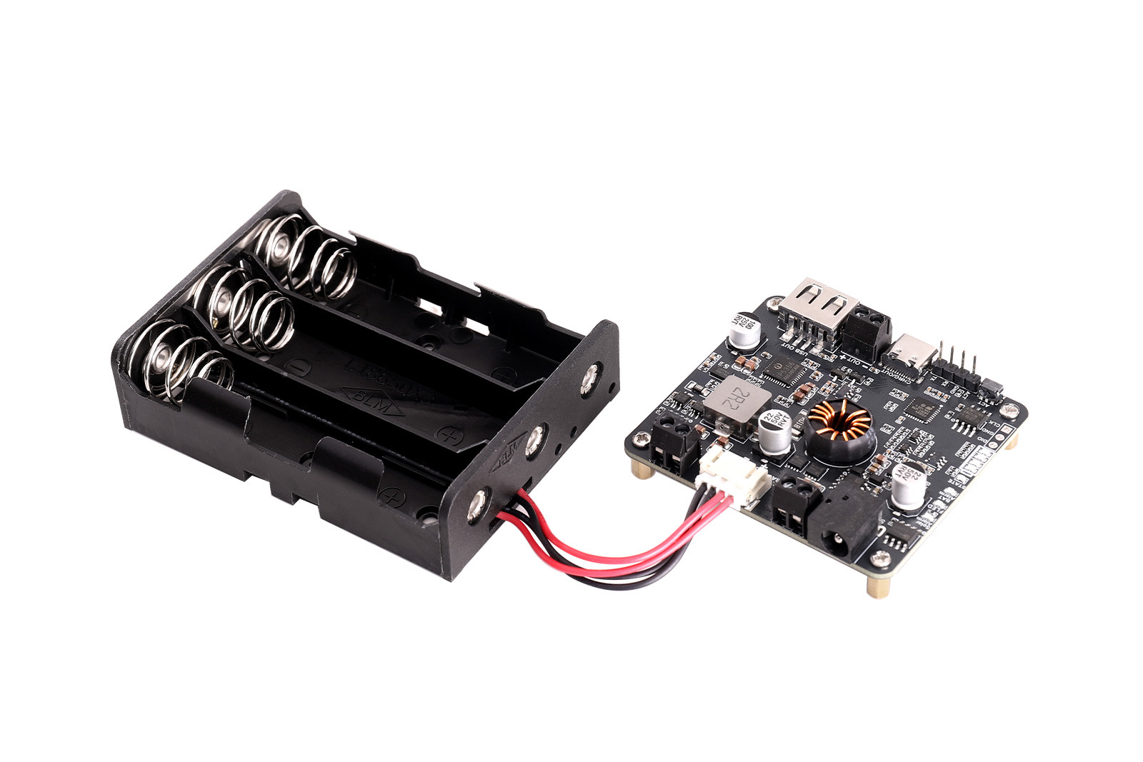
- Onboard 3.5 mm terminal block and PH2.0-4P battery connector for easy connection to various 3.7 V rechargeable lithium batteries or battery packs
- Multiple onboard status LEDs for checking battery charge/discharge status and remaining battery capacity
- Supports battery capacity learning and setting; corrects the effective battery capacity based on actual charge/discharge processes
- Onboard overcharge/over-discharge/reverse-connection/overcurrent protection circuits for stable and safe operation
III. Specifications
| Parameter | Specification |
|---|---|
| Solar Panel Input Voltage | 5–24 V |
| Maximum Solar Charging Power | Approx. 20 W |
| USB Type-C Input/Output Voltage | 5 V / 9 V / 12 V |
| USB-A or Terminal Block Output | 5 V / 3.1 A |
| Charge Cutoff Protection Voltage | 4.2 V ±1% |
| Over-discharge Protection Voltage | 3.0 V ±1% |
| Battery Charging Efficiency | Solar: max. approx. 92%; USB: max. approx. 93% |
| Battery Boost Output Efficiency | Approx. 92% |
| Maximum Quiescent Current (Non-charging/Discharging) | Approx. 15 mA |
| Sleep Current (Sleep Mode) | Approx. 2 mA |
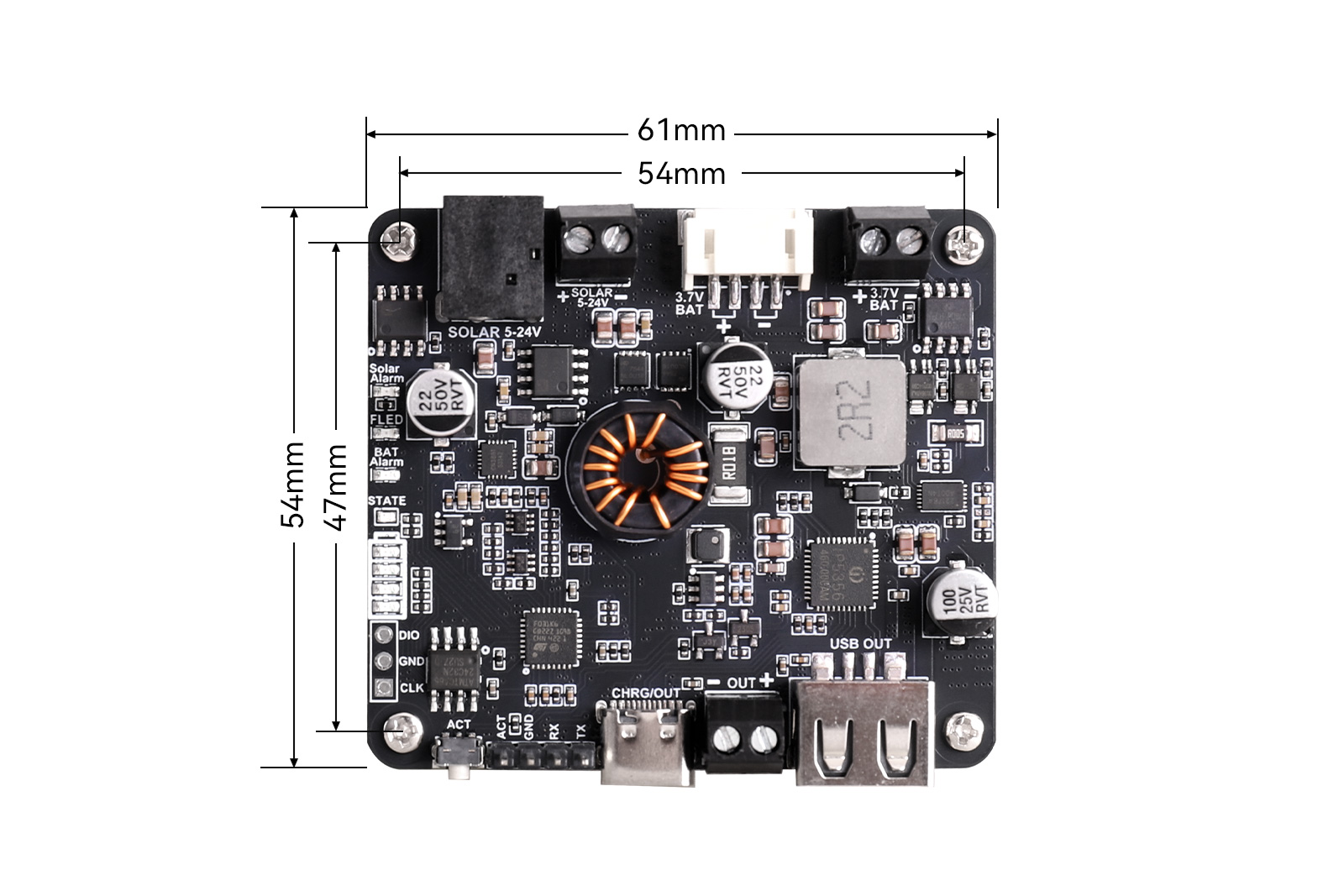
| Dimensions | 61 mm (L) × 54 mm (W) |
IⅤ. Resource Overview
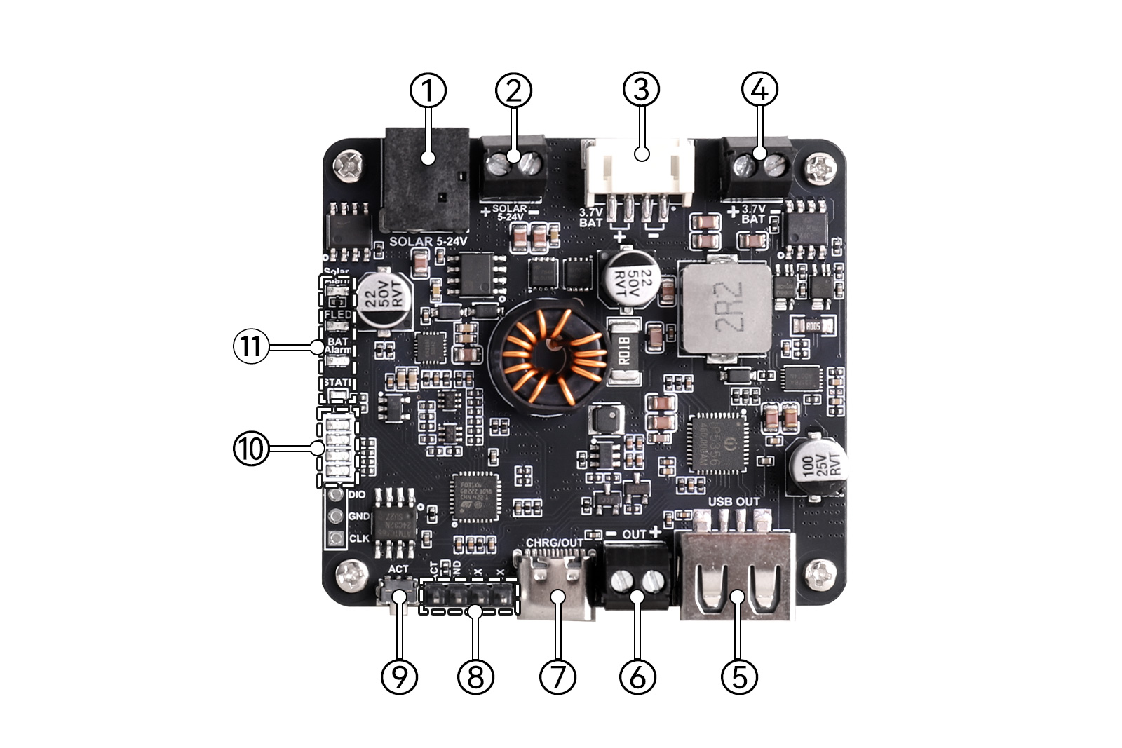
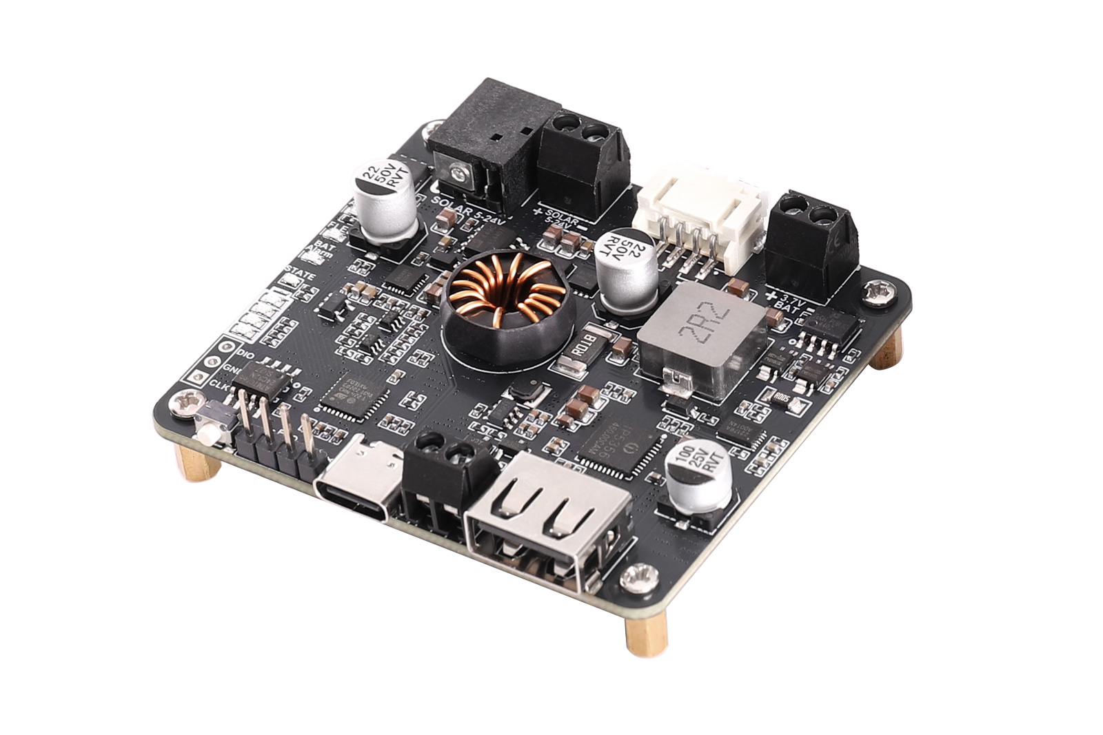
① DC-044 Solar Charging Jack: Connect a solar panel through this power jack.
② 3.5 mm Solar Charging Terminal: Connect a solar panel through this terminal block.
③ PH2.0-4P Battery Input Connector: Connect a 3.7 V rechargeable lithium battery through this connector.
④ 3.5 mm Battery Input Terminal: Connect a 3.7 V rechargeable lithium battery through this terminal block.
⑤ USB-A Output Connector: Discharge to an external load through this connector.
⑥ 3.5 mm Output Terminal: Output up to 5 V/3.1 A to an external device through this terminal block.
⑦ USB-C Charge/Discharge Connector: Charge the battery or discharge through a Type-C cable; supports PD/QC/FCP/PE/SFCP and other protocols.
⑧ Debug Header Pads: TX and RX pins are STM32 UART pins. Through these pins, status information can be exchanged with the system. The ACT pin is connected to the ACT button.
⑨ Output Activation Button: If the board enters lockout due to low battery voltage, press this button to activate output. In working state, short press to put the system into sleep mode; long press for 8 seconds to enter battery capacity learning mode.
⑩ Battery Capacity Indicator: Displays battery capacity obtained by the system. Levels are 1–25%, 26–50%, 51–75%, and 76–100%. When battery capacity is 1–25%, the bottom LED lights and the others are off; at 26–50%, the bottom two LEDs light; and so on.
⑪ System Status Indicators:
- Solar Alarm: Solar input polarity reverse indicator
- FLED: Fast charging indicator
- BAT Alarm: Battery polarity reverse indicator
- STATE: IP5356M chip status indicator
WIKI
https://seengreat.com/wiki/222/
Package Contents
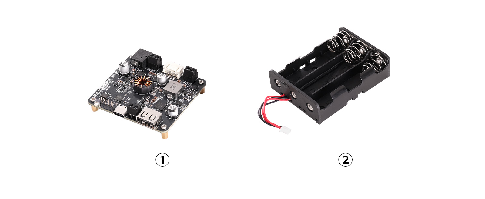
①Solar Energy Manager F Module x1
② Battery holder x1