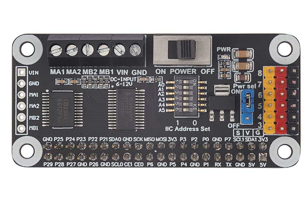
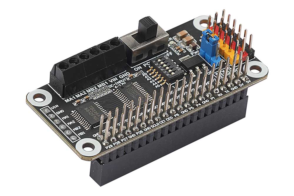
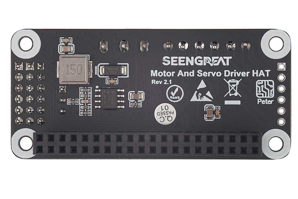
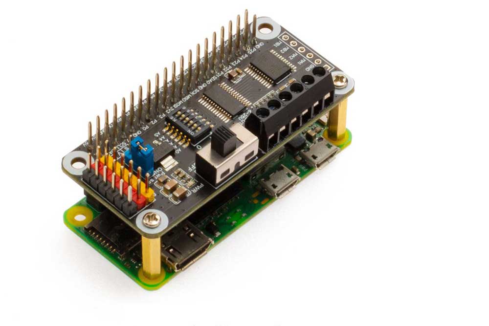
This product is based on 40P header design of Raspberry Pi, suitable for Raspberry Pi Zero/Zero W/Zero WH/2B/3B/3B+/4B, adopting PCA9685+TB6612 chip solution. It can control 2 channels of DC motors and 6 channels of servos at the same time.
Chip Introduction:
PCA9685:
- Adopting I2C communication, built-in PWM driver and a clock, no need to continuously send signals to occupy the resources of the micro-controller.
- Supporting 16 channels of PWM output. Each channel has 12-bit resolution (4096 levels), and can reach 4us resolution at 60Hz update rate .
- Internal 25MHz crystal oscillator. It ether can be connected with external crystal oscillator, maximum 50MHz, nor can not be connected with external crystal oscillator.
- Divided into two power supplies: control and driving. The control power supply supports 2.3V-5.5V voltage, and the maximum withstand voltage is 5.5V. The logic level is 3.3V, and the driving power supply supports 5V-10V DC voltage.
TB6612FNG:
- High current MOSFET-H bridge structure;
- Dual-channel circuit output. It can drive 2 motors at the same time;
- Continuous driver current from each channel up to 1 A;
- Starting peak current up to 2A/3A (continuous pulse/single pulse);
- 4 modes of motor: forward/reverse/brake/stop;
- Supporting frequencies of PWM up to 100 kHz.
Specifications
| Supply Voltage | 6V~12V(VIN terminal or pin) |
| Logic Voltage | 3.3V |
| PWM Driver Chip | PCA9685 |
| Communication Interfaces | I2C |
| Motor Driver Chip | TB6612FNG |
| Dimensions | 65mm(Length) x 30mm(Width) |
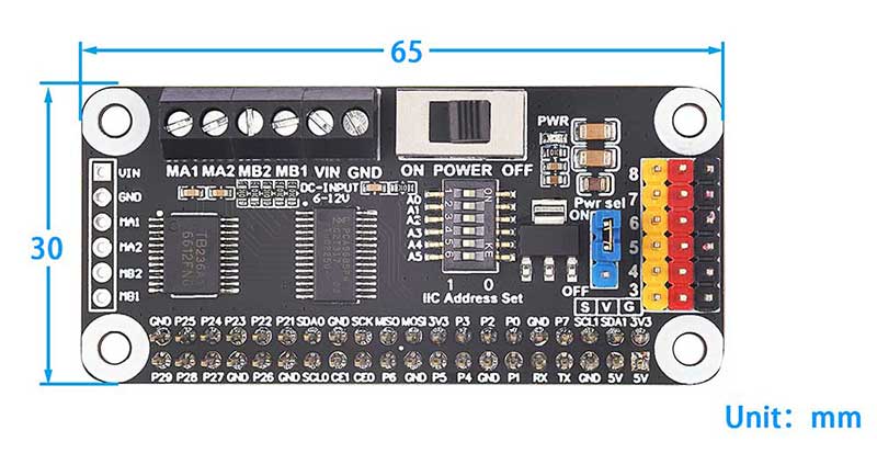
Interface Introduction
Motor And Servo Driver HAT has designed a separate power switch. After power on, the POWER needs to be turned to the ON position. In addition, all the address lines of I2C are led out, and the address can be set by means of the DIP switch. The demo codes we provide are set the address to 0X7F, and the DIP switch settings are as follows:
* Hardware Connection: Switch
*          A0 -> OFF                   A1 -> OFF
*          A2 -> OFF                   A3 -> OFF
*          A4 -> OFF                   A5 -> OFF
The interface definition is shown in the following figure:
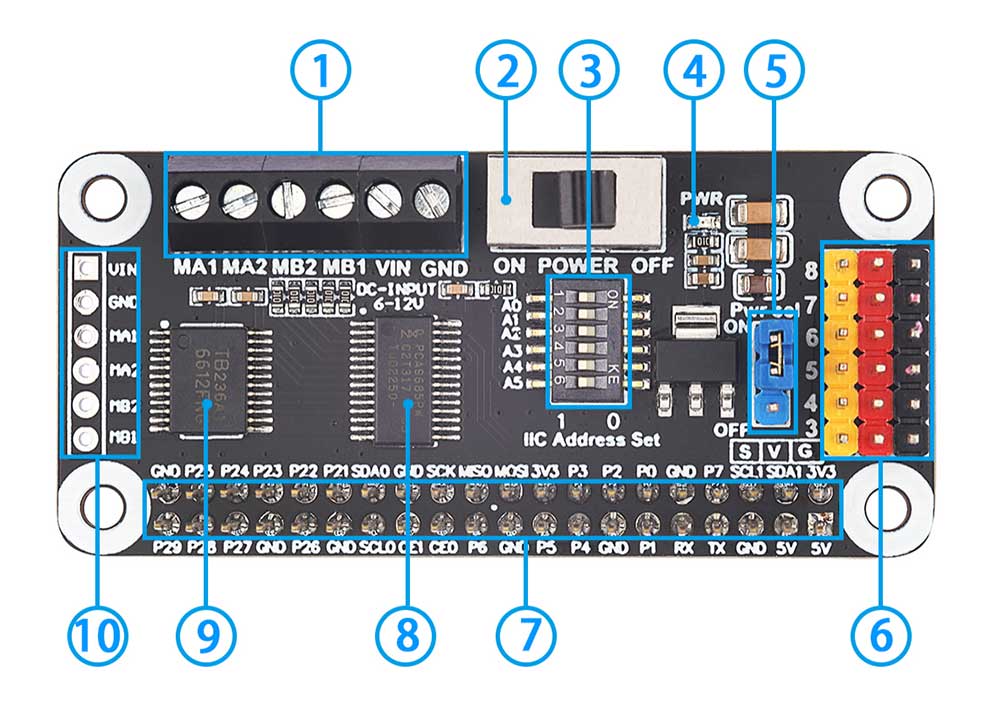
1、Motor A、Motor B and Drive power input terminal block
2、Drive power switch
3、I2C address setting DIP switch: all I2C address lines are led out, and the address can be set through the DIP switch.
4、Power Indicator
5、5V power jumper cap: Select whether the 5V power supply of the module is connected to the 5V from Raspberry Pi
6、6 servos interface header
7、Raspberry Pi 40pin GPIO header
8、PWM driver chip PCA9685
9、Motor driver chip TB6612FNG
10、Motor A、motor B andpower input connector(2.54mm pitch header can be soldered)
WIKI
Package Contents
- 1. Motor And Servo Driver HAT x1
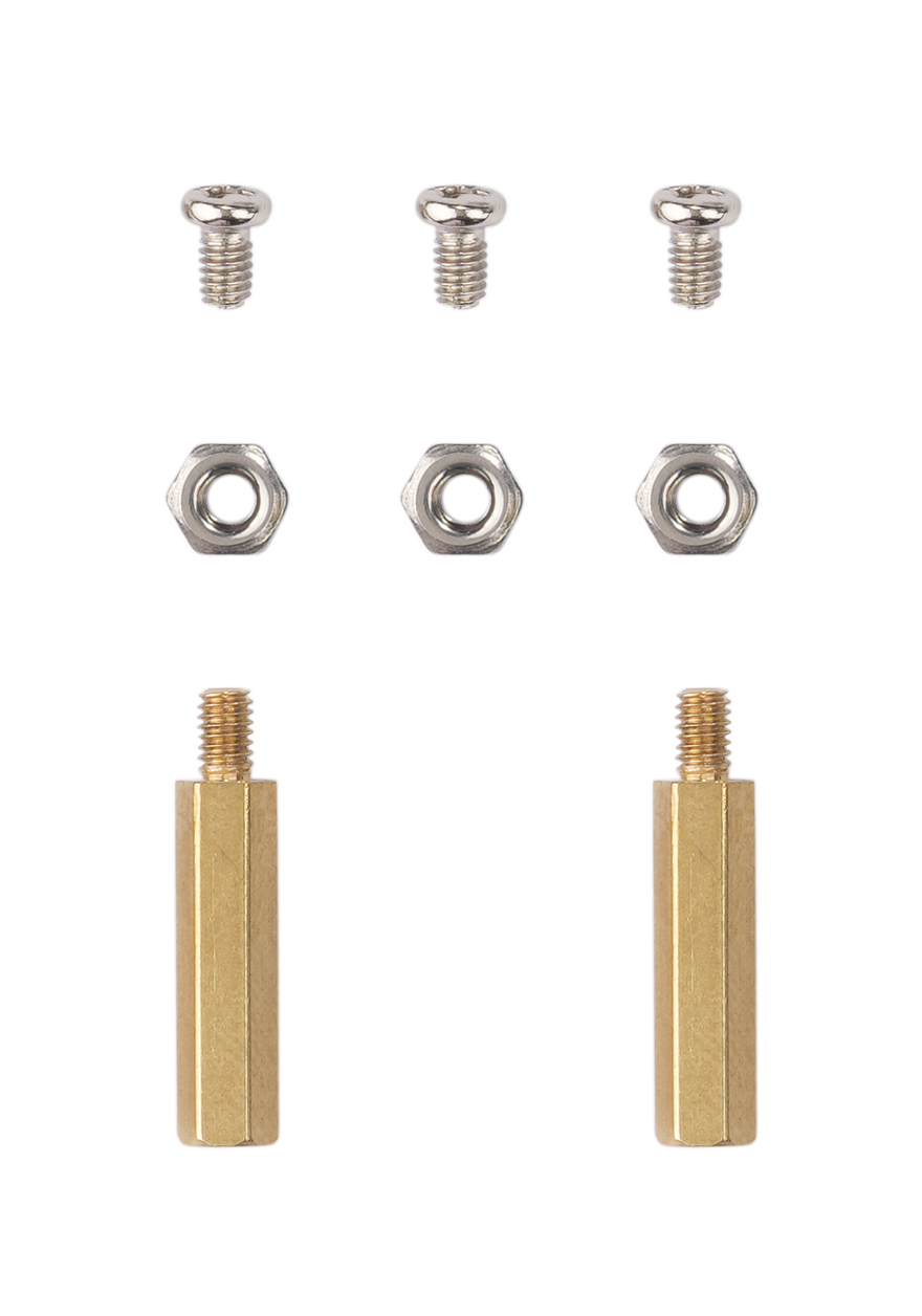
- 2. Accessory pack
1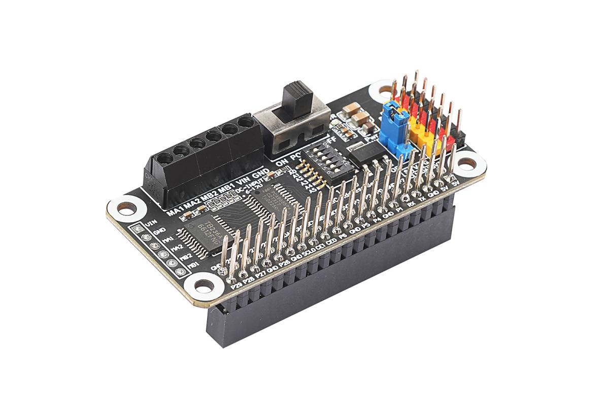 2
2