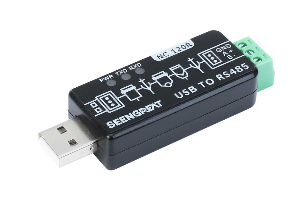
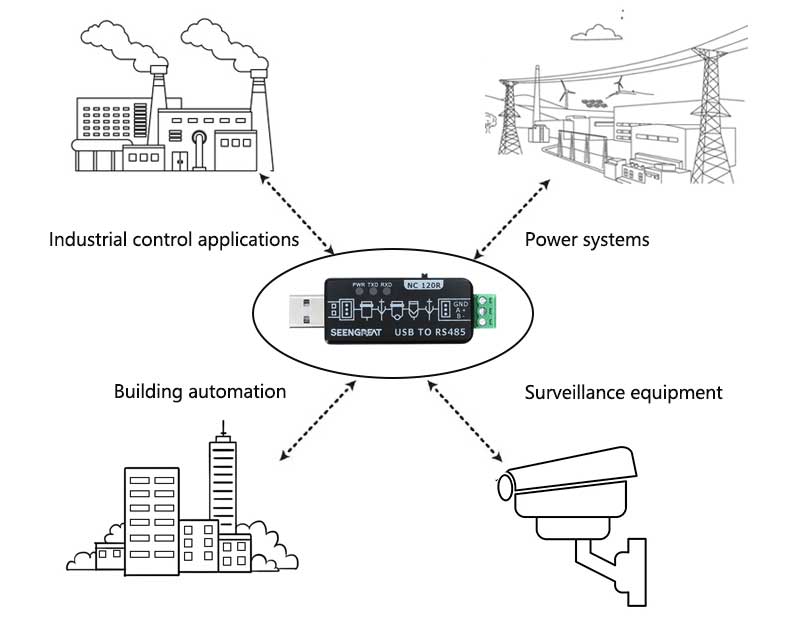
An USB to RS485 converter is a practical tool that allows traditional RS485 interface devices to connect to modern computers with ease. By correctly using an USB to RS485 converter, stable and efficient bidirectional data transfer and device control can be achieved. RS485 to USB converters have a wide range of applications in fields such as industrial automation, data acquisition, and remote control.
RS485 Interface Working Principle
Differential Transmission Principle: The RS485 interface uses differential transmission technology, with two signal wires (A and B) transmitting signals of positive and negative polarity, respectively. The receiving end recovers the data based on the differential voltage, thereby achieving reliable communication.
Data Frame Format: The data frame of the RS485 interface consists of start bits, data bits, stop bits, and parity bits. The sending end encapsulates the data into a data frame according to certain rules and sends it to the receiving end, which then parses the data frame and processes it.
RS485 Interface Communication Protocol
The RS485 interface utilizes a half-duplex communication method, allowing multiple devices to communicate through the same bus. It employs differential signal transmission, which effectively resists electromagnetic interference and is suitable for long-distance transmission. MODBUS is a communication protocol based on the RS485 interface, commonly used in the industrial sector. It defines standards for data transfer formats, commands, and register addresses, enabling data exchange and control between devices.
RS485 Interface Transmission Modes
The RS485 interface provides two transmission modes: multi-host mode and single-host mode.
Multi-Host Mode: In multi-host mode, multiple devices can send and receive data simultaneously. This mode is suitable for scenarios where free communication and sharing of bus resources between multiple devices are required. However, due to the potential for protocol conflicts and data collisions, multi-host mode must be properly configured and managed to avoid communication conflicts and data errors.
Single-Host Mode: In single-host mode, only one device acts as the master, with all other devices functioning as slaves. The master controls the data transmission and sends data to the slaves for processing. This mode simplifies the management and scheduling of communications and provides more reliable data transmission.
The choice of transmission mode should be based on specific application requirements and system architecture, considering factors such as the complexity of communication, data security, and system stability.
RS485 Interface Data Format and Frame Structure
RS485 is a commonly used standard for serial communication interfaces, which defines the transmission format and frame structure of data. Here is the common data format and frame structure for the RS485 interface:
Start Bit: The first bit of the data frame, used to indicate the beginning of data transmission.
Data Bits: Data bits are used to transmit the actual data information. The RS485 interface typically supports 7 or 8 data bits.
Stop Bit: The last bit of the data frame, used to indicate the end of data transmission.
Parity Bit: The parity bit is used to detect errors during data transmission. It can be either odd or even parity, used to verify the odd or even number of data bits.
The data frame structure of the RS485 interface can be similar to the following form: Start Bit + Data Bits + Parity Bit + Stop Bit.
Usage Notes
When using an USB to RS485 converter, pay attention to the following things:
Interface Type. Ensure that the USB interface type of the converter (such as USB Type-A, Type-C, etc.) is compatible with your device.
Communication Rate. Choose a converter that supports the required communication rate (baud rate).
Driver Software. Although many converters are plug-and-play and do not require drivers, some specific applications may require the installation of specific driver software.
Software Compatibility. Ensure that the converter is compatible with your operating system and application software.
Troubleshooting and Solutions
Signal Issues and Solutions
When using the RS485 interface, you may encounter signal issues and faults. Here are some common methods for RS485 interface signal debugging and troubleshooting:
- Check Connections: Ensure that the connections to the RS485 interface are correct, including cable connections, terminal resistor settings, and grounding issues.
- Use an Oscilloscope: Observe the signal waveform with an oscilloscope to check for interference or distortion problems.
- Adjust Driver and Receiver Parameters: Adjust the transmission rate, terminal resistors, and gain of the drivers and receivers according to the specifications and requirements of the devices to ensure normal signal transmission.
- Eliminate Electromagnetic Interference: In industrial environments, electromagnetic interference is a common issue. Appropriate shielding measures, such as using shielded cables and filters, can effectively reduce interference.
Data Communication Failure and Solutions
Here's a breakdown of the troubleshooting steps to follow if you're experiencing data communication failure with an RS485 to USB converter:
- USB Interface Connections: Ensure that the USB cable is properly connected to both the converter and the computer or other USB device. Also, check if the USB port is functioning correctly by testing it with another device.
- RS-485/422 Output Interface Connections: Confirm that the RS-485/422 connections are correctly wired according to the specifications of the devices in use. This includes checking for proper termination and ensuring that no pins are bent or damaged.
- Power Supply: Check that the converter is receiving adequate power. If it's an external device, make sure it's plugged into a working power source. For internal devices, ensure that the computer or system it's installed in is powered on.
- Terminal Connections: Inspect the terminal blocks or connectors for any loose or poor connections. A bad connection can disrupt data flow.
- Receive Indicator Light: The receive indicator light should flash or blink when data is being received. If it's not, this could indicate a problem with the data reception.
- Transmit Indicator Light: Similarly, the transmit indicator light should show activity when data is being sent. No activity could suggest an issue with the data transmission.
If after checking these points the issue still persists, consider the following additional steps:
1 Cable Quality: Poor quality or damaged cables can cause communication issues. Try using a different cable to rule out this possibility.
2 Device Drivers: If the converter requires a driver, make sure it's up to date and properly installed.
3 Device Settings: Check the settings of both the converter and the connected devices to ensure they match in terms of baud rate, data bits, stop bits, and parity.
4 Software Configuration: Ensure that the software you're using to communicate with the RS485 device is configured correctly.
5 Hardware Conflicts: There might be a hardware conflict on the USB port or with other devices sharing the same communication bus. Try using a different port or power source.
6 Professional Help: If you're unable to resolve the issue, it may be necessary to consult with a professional or the manufacturer's support team.
 Comments