Overview
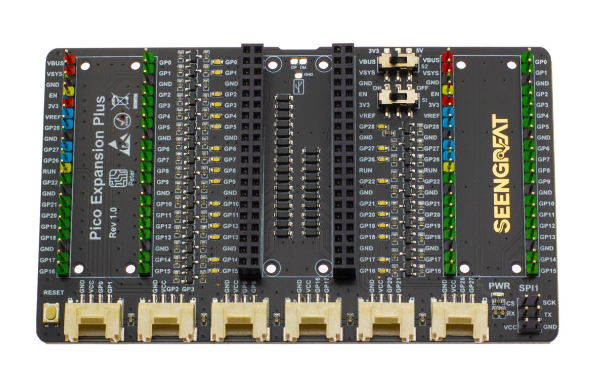
Pico Expansion Plus is an expansion board designed specifically for the Raspberry Pi Pico, with all Pico status indicator LEDs for GPIO, two sets of 2*20 external expansion pins, six HY-2.0-4P connectors, a group of SPI1 interface (pin header form) and a reset button.
GPIO LED Indicators: The GPIO status display function can be turned on by toggling the switch S1 to the ON state. At this time, when the GPIO is at a high level, the corresponding LED indicator LED is on, otherwise the LED is off. If you do not need to display the GPIO status through the LED status, you can turn the switch S1 to the OFF state.
It is easy of Two sets of 2*20 pins to access to the Raspberry Pi Pico expansion board or dupont wire to peripherals. Both sides of the board are marked with clear pin function silk screen, which is convenient for use and measurement.
The 6 HY-2.0-4P connectors can be inserted into 2.0-spaced cables. It is quick and convenient to connect to other functional modules. Through the DIP switch S2, select the power supply voltage of the modules which are connected to these connectors. At that time, when the DIP switch S2 was turned to 5V, the power supply voltage of the connected module was 5V, and when the DIP switch S2 was turned to 3.3V, the power supply voltage of the connected module was 3.3V. Note: The VCC terminals of all externally expanded HY-2.0-4P connectors are connected together, so when the power supply voltage is selected, the power supply voltage of all externally expanded HY-2.0-4P connectors will become the same.
A group of pin headers leads to the SPI1 interface, which can be connected to the SPI peripheral module through flat cables or DuPont cables. The SPI1 interface is consistent with the VCC voltage of the six connectors.
Raspberry Pi Pico does not have a reset button, bit this product increases the reset button, so it is convenient for users to debug or write programs without frequent plugging USB line of Pico.
Specifications
- 5V Working voltage
- 26 GPIO Indicators
- 2 sets of 2*20 external expansion pins
- 6 HY-2.0-4P connectors
- A group of SPI1 interface (pin header form)
- A reset button
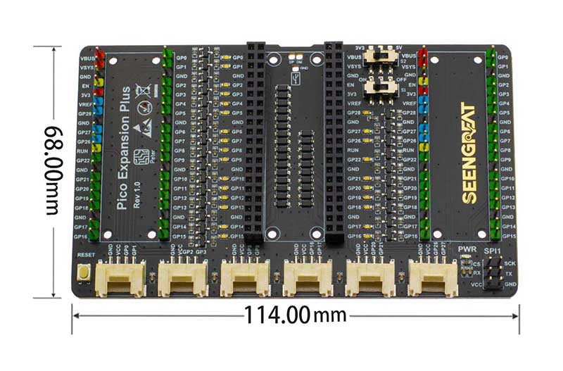
- Dimensions: 114mm(L) x 68mm(W) x 11mm(H)
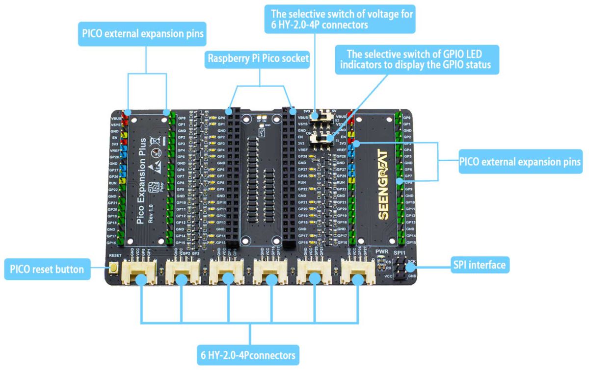
Resource Profile
Module Resource Profile is shown in the figure below
Usage
Hardware Interface Configuration
It is easy of two sets of 2*20 pins to access to the Raspberry Pico expansion board or dupont wire to peripherals. Both sides of the board are marked with clear pin function silk screen, which is convenient for use and measurement.
The 6 HY-2.0-4P connectors can be inserted into 2.0-spaced cables. It is quick and convenient to connect to other functional modules. Through the DIP switch S2, select the power supply voltage of the modules which are connected to these interfaces. At that time, when the DIP switch S2 was turned to 5V, the power supply voltage of the connected module was 5V, and when the DIP switch S2 was turned to 3.3V, the power supply voltage of the connected module was 3.3V.
Note: The VCC terminals of all externally expanded HY-2.0-4P connectors are connected together, so when the power supply voltage is selected, the power supply voltage of all externally expanded HY-2.0-4P connectors will become the same.
A group of pin headers leads to the SPI1 interface, which can be connected to the SPI peripheral module through flat cables or DuPont cables. The SPI1 interface is consistent with the VCC voltage of the six HY-2.0-4P connectors.