Dual-CH CAN HAT is a professional expansion board specially developed for Raspberry Pi for learning or testing the dual-channel CAN communication function with multiple protections. At the same time, it also leads to the SPI jumper wire pin interface for STM32, Arduino and other host control boards.
Features
- Based on Raspberry Pi design, suitable for Raspberry Pi Zero/Zero W/Zero WH/2B/3B/3B+/4B
- Adopt MCP2515 and ATA6561 dual-chip combination solution, support dual-channel CAN interface communication
- Onboard level conversion circuit, the working level of 3.3V/5V can be switched by slide switch
- Onboard 120Ω terminal resistor, it can be set Enable by slide switch
- Leads out the SPI control interface, for connecting with host control boards like STM32/Arduino
- Provide complete supporting information manuals and demo codes
Specifications
| Input Voltage | 5V |
| Logic Voltage | 3.3V/5V |
| CAN Control Chip | MCP2515 |
| CAN Transceiver | ATA6561-GAQW-N |
| Dimensions | 65mm(length) x 56mm(width) |
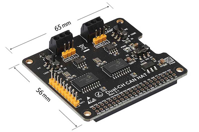
Definition of Interfaces
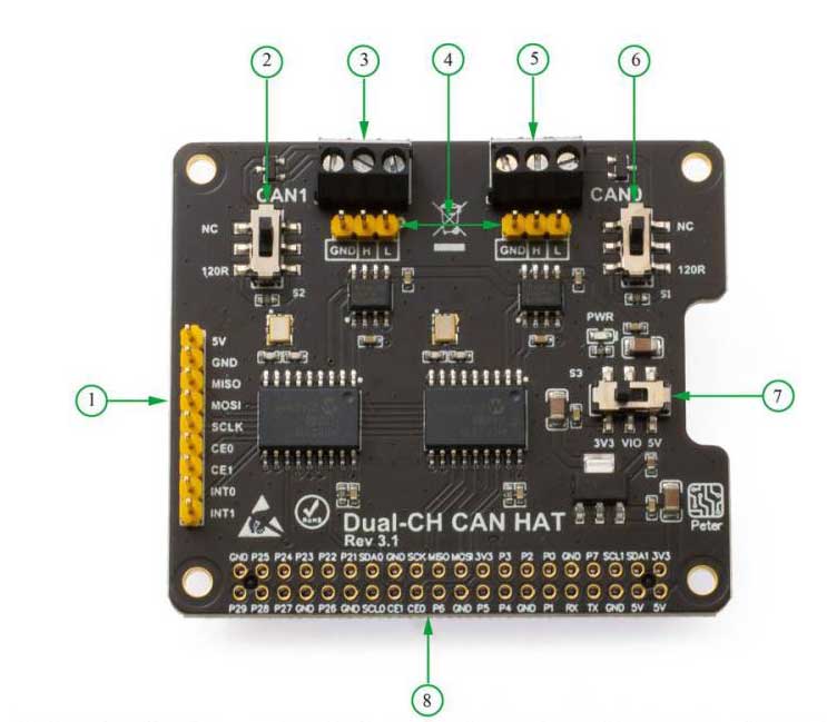
- 1. Pin header leads out the SPI control interface, for connecting with host controllers like STM32/Arduino
- 2. CAN1 120Ω terminal resistance selective slide switch
- 3. CAN1 interface
- 4. Leads out the pin header from CAN0, CAN1 interface
- 5. CAN0 interface
- 6. CAN0 120Ω terminal resistance selective slide switch
- 7. 3.3V/5V logic voltage selective slide switch
- 8. Raspberry Pi GPIO connector
Usage
Instructions of Hard Interface Configuration
The level of Raspberry Pi and STM32 logic system is 3.3V, users need to pull the logic voltage control switch S3 of the board to 3.3V when use Dual CAN HAT.
▲STM32 Hardware Connection
* Hardware Connection :STM32F103 -> Dual-CH CAN HAT
* CAN0_H -> CAN1_H                                            CAN0_L -> CAN1_L
* 5V -> 5V                                                                PB15 -> MOSI
* GND -> GND                                                         PB14 -> MISO
* PB3 -> INT0                                                          PB13 -> SCK
* PB4 -> INT1                                                          PB12 -> CE0
*                                                                               PB5   -> CE1
▲Raspberry Pi Interface Definition
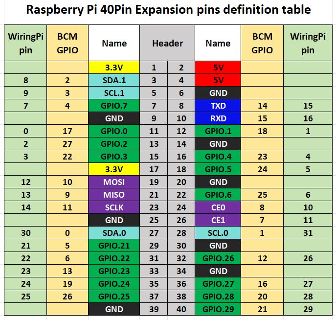
The pin definitions for connecting Dual CAN HAT to Raspberry Pi are shown in Table 2-1 below.
| Function Pin | Raspberry Pi Connector(BCM) | Raspberry Pi Connector(WPI) | Description |
|---|---|---|---|
| 5V | 5V | 5V | 5V VCC |
| GND | GND | GND | GND |
| MISO | 9(MISO) | 13(MISO) | SPI Data Output |
| MOSI | 10(MOSI) | 12(MOSI) | SPI Data Input |
| SCK | 11(SCLK) | 14(SCLK) | SPI Clock Input |
| CS_0 | 8(CE0) | 10(CE0) | CAN_0 Chip Select |
| INT_0 | 25 | 6 | CAN_0 Interrupt Output |
| CS_1 | 7(CE1) | 11(CE1) | CAN_1 Chip Select |
| INT_1 | 23 | 4 | CAN_1 Interrupt Output |
▲Hardware Setup
Turn the slide switch to 3v3,the terminal resistance slide switch also to the same setting, and then plug the module into Raspberry Pi.
Configuration Environment
Install the Necessary Function Library
Install wiringPi Library:
sudo apt-get install wiringpi
wget https://project-downloads.drogon.net/wiringpi-latest.deb #Version 4B upgrade of Raspberry Pi
gpio -v
If version 2.52 appears, it indicates a successful installation
For the Bullseye branch system, use the following command:
git clone https://github.com/WiringPi/WiringPi
cd WiringPi
./build
gpio -v
Running "gpio -v "will show version 2.70. If it does not appear, it means the installation is incorrect
If you encounter the error message "ImportError: No module named 'wiringpi'" when running the Python version of the example program, run the following command
For Python 2. x version
pip install wiringpiFor Python 3. x version
pip3 install wiringpiNote: If the installation fails, you can try the following compilation and installation:
git clone --recursive https://github.com/WiringPi/WiringPi-Python.gitNote: The--recursiveoption allows for automatic pulling of submodules; otherwise, you need to manually download them.
Go into the downloaded WiringPi-Python folder and enter the following command to compile and install it:
For Python 2. x version
sudo python setup.py installFor Python 3. x version
sudo python3 setup.py installIf the following error occurs:

At this point, enter the command "sudo apt install swig" to install swig. Once completed, proceed with "sudo python3 setup.py install" to compile and install. If you see similar information as below, it indicates a successful installation.

●Install Python Function Library
#python3
sudo apt-get update
sudo apt-get install python3-pip
sudo apt-get install python3-pil
sudo apt-get install python3-numpy
sudo pip3 install spidev
sudo pip3 install python-can
Configure SPI for Raspberry Pi
● Enable SPI for Raspberry Pi
Enter the following command to enter the setting interface of the Raspberry Pi and enable the SPI interface.
sudo raspi-configSelect Interfacing Options -> SPI -> Yes to enable the SPI interface
● Load the MCP2515CAN driver into the kernel
Enter the following command to edit the boot configuration file of the Raspberry Pi
sudo nano /boot/config.txtAdd the following three lines of code at the end of the document
dtparam=spi=on
dtoverlay=mcp2515-can0,oscillator=16000000,interrupt=25
dtoverlay=mcp2515-can1,oscillator=16000000,interrupt=23
Reboot the Raspberry Pi to apply the changed settings
sudo reboot● Test whether the configuration is successful
After the Raspberry Pi reboot, check the SPI information
dmesg | grep spi0The following figure appears means the initialization is successful

Test
Command Line Test
If there is only one Raspberry Pi and Dual-CH Can HAT module, CAN0 and CAN1 can be connected(The H pins of the two can interfaces are connected, and the L pins are connected).
Firstly, install the can test tool can-utils on the command line:
sudo apt-get install can-utilsThen open the can interface with the following commands:
sudo ip link set can0 up type can bitrate 1000000
sudo ip link set can1 up type can bitrate 1000000
Open two terminals first when carry out transceiver test, and the following test process is to send data from Can1 to can0:
One of the terminal inputs receives CAN0 data command
candump can0
Another terminal input sends CAN1 data command
cansend can1 000#11.22.33.44
The demonstration effect is as follows:


Python demo codes
can1 sends data to can0:
First, open two terminals. One terminal is used to run the data receiving code, and the other terminal is used to run the data sending code. Run the data receiving code first and then the data sending code.
cd #Own file directory/dual-can/python/can0
python3 rev-can0.py
Another terminal input:
cd #Own file directory/dual-can/python/can1
python3 send-can1.py
Notice:
If an error similar to the following occurs during the running of the python program:
RTNETLINK answers:Device or resource busy
Traceback (most recent call last):
File "xxxxx.py", line xx, in
can0 = can.interface. Bus(channel = ‘can0', bustyp = ‘socketcan_ctypes')
File "....xxxx.py", line xxx, in new
kwargs = load_config(config=kwargs, context=context)
File "/usr/local/lib/python3.7/dist-packages/can/util.py", line 192, in load_config
f'Unknown interface type "{config[interface]}"'
can.exceptions. CanInterfaceNotImplementError:Unknown interface type "None"
Solution:
Add the .canrc file under ~/,
sudo nano ~/.canrcFill in the following contents:
[default]
interface = socketcan
channel = can0
Exit after saving, reboot and rerun the Python code.
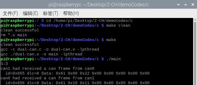
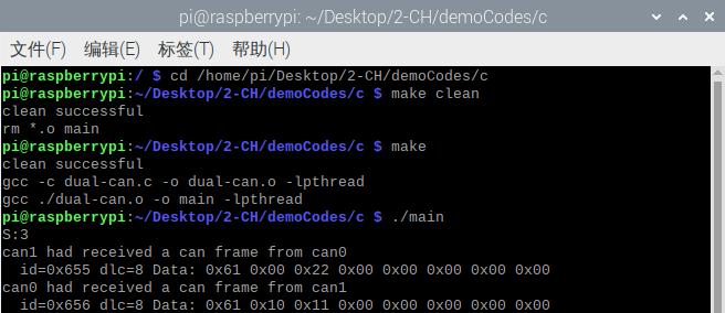
● C demo codes
Execute the following command to move to the program directory
cd #Own file directory/dual-can/c
Then execute the following commands in sequence
sudo make clean
sudo make
sudo ./main
The program runs as shown in the following figure
STM32 Demo codes usage
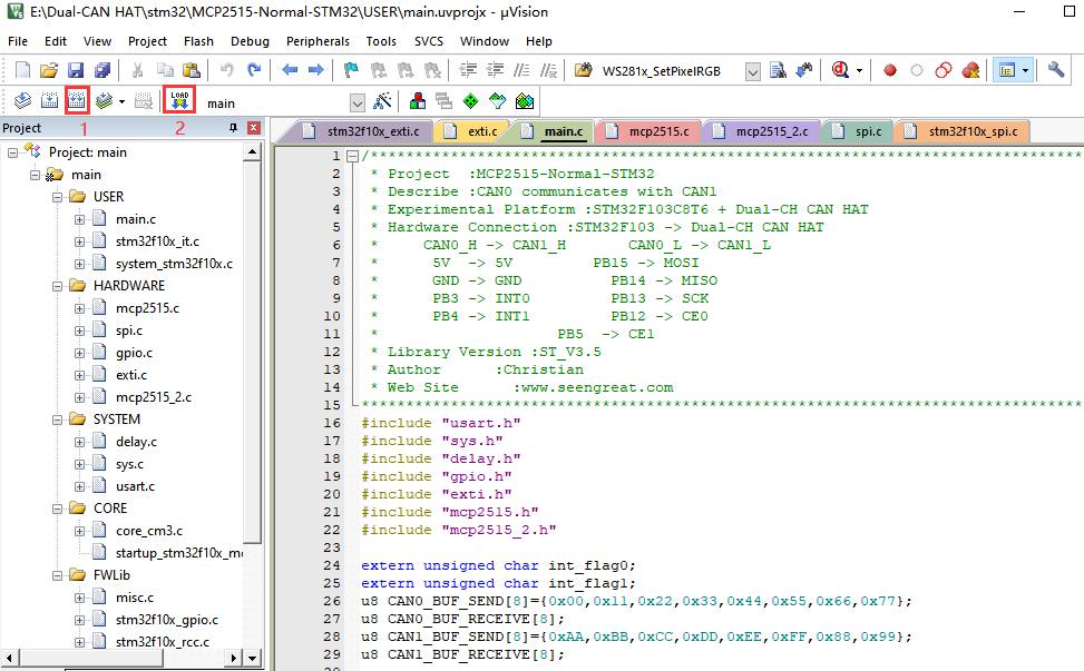
Open the main. Uvprojx project file in the directory demo codes\stm32\MCP2515-Normal-STM32\USER with Keil_Vision5 software, and connect the module with STM32 according to the above table; The program is downloaded to the STM32 development board after being compiled without errors;
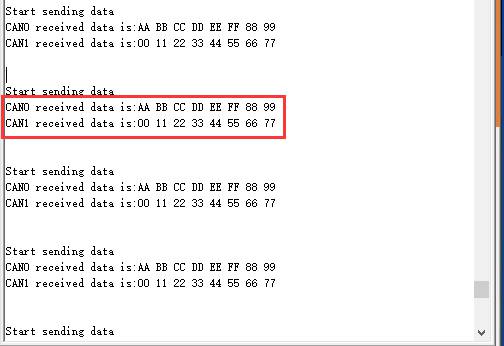
The debugging information output serial port in the demo codes is USART1, where PA9 is Tx and PA10 is Rx; After connecting the cable, open the Serial Port Debugging Assistant, select the serial port number, adjust the baud rate to 9600, click "Open", and the Serial Port Debugging Assistant window is shown as follows:
Resources
Data Sheet
