Overview
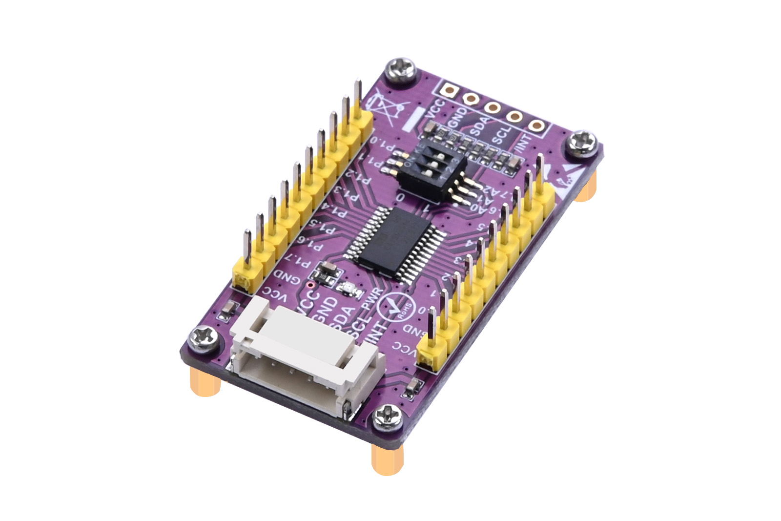
This product provides 16−bit parallel input/output port expansion for I2C and SMBus compatible applications. These I/O expanders provide a simple solution in applications where additional I/Os are needed: sensors, power switches, LEDs, buttons, and fans.
The communication interface of this product is I2C, and the maximum communication rate is 400KHz. The board also leads out a PH2.0 5Pin socket, a 2.54 pitch pin header and all IO expansion ports. We provide demo codes based on Raspberry Pi, Arduino UNO, and STM32, which are convenient for users to use on different platforms.
Parameters
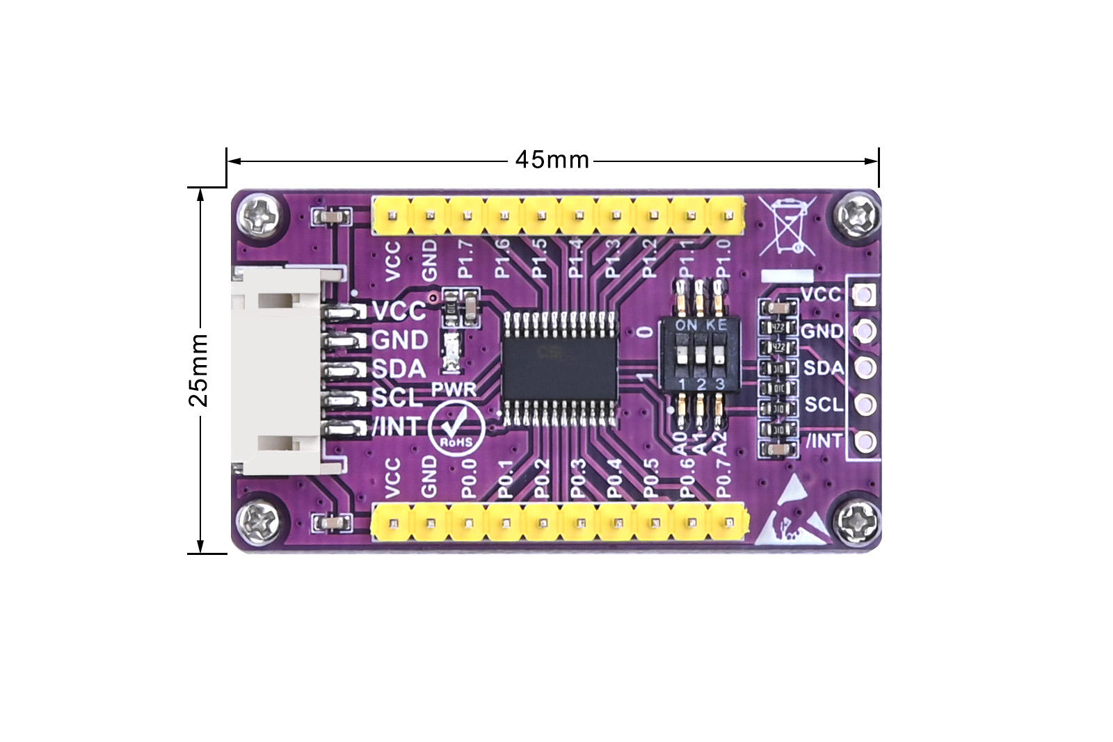
| DIMENTIONS | 45mm(Length) x 25mm(Width) |
| NUMBER OF I/O PORTS | 16 |
| CONTROL CHIP | CAT9555 |
| SIGNAL INTERFACE | I2C |
| SUPPLY VOLTAGE | 3.3V/5V |
| Dimensions | 45mm(L) x 25mm(W) |
Usage
Since the bookworm system no longer supports the wiringpi library, the example program for this system uses the lgpio library, and for the bullseye system, the wiringpi library version of the example program can be used.
Wiring Instructions of Raspberry Pi
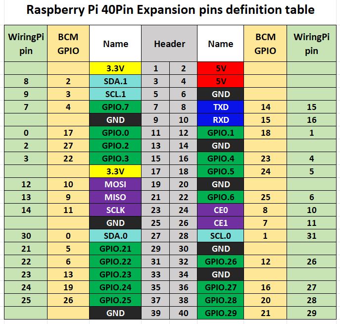
The demo codes in the Raspberry Pi motherboard adopts the pin definitions number by wiringPi, and the bookworm system uses the pin definition of the BCM number. the definition of the wiring with the Raspberry Pi motherboard is shown in the following table:
| Connector | Pin Function | BCM Number | WiringPi Number | BOARD Number |
|---|---|---|---|---|
| VCC | 3.3V | 3.3V | 3.3V | 1 |
| GND | GND | GND | GND | 6 |
| SDA | SDA.1 | 2 | 8 | 3 |
| SCL | SCL.1 | 3 | 9 | 5 |
| INT | GPIO.7 | 4 | 7 | 7 |
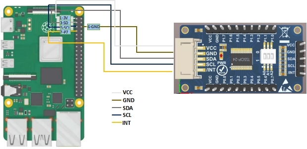
The Raspberry Pi is connected to the module, and the wiring diagram is shown in Figure 2-1.
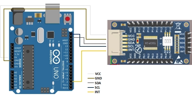
Wiring Instructions of Arduino
The wiring between the module and Arduino pins is shown in the following table:
| CAT9555 IO Expansion Module | Arduino UNO R3 |
| VCC | 5V |
| GND | GND |
| SDA | SDA |
| SCL | SCL |
| INT | D2 |
Wiring Instructions of STM32
The wiring between the module and STM32F103 pins is shown in the following table:
| CAT9555 IO Expansion Module | STM32F103 |
| VCC | 3.3V |
| GND | GND |
| SDA | PB10 |
| SCL | PB11 |
| INT | PB3 |
Device Addressing
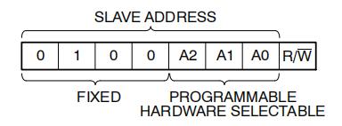
After the bus Master sends a START condition, a slave address byte is required to enable the CAT9555 for a read or write operation. The four most significant bits of the slave address are fixed as binary 0100 (Figure 2-3). The CAT9555 uses the next three bits as address bits. The address bits A2, A1 and A0 are used to select which device is accessed from maximum eight devices on the same bus. These bits must compare to their hardwired input pins.
The 8th bit following the 7−bit slave address is the R/W bit that specifies whether a read or write operation is to be performed. When this bit is set to "1", a read operation is initiated, and when set to "0", a write operation is selected. Following the START condition and the slave address byte, the CAT9555 monitors the bus and responds with an acknowledge (on the SDA line) when its address matches the transmitted slave address. The CAT9555 then performs a read or a write operation depending on the state of the R/W bit.
When the on-board DIP switch is turned to the "ON" state, the address state on this bit is low level ("0"), and when it is turned to the other side, it is high level ("1"),The status settings of A2 A1 A0 are shown in the following table:
| I2C Address line | DIP switch "ON" state | DIP switch "OFF" state |
|---|---|---|
| A0 | 0 | 1 |
| A1 | 0 | 1 |
| A2 | 0 | 1 |
Usage of Demo Codes
Usage of Demo Codes for Raspberry Pi
1. wiringpi Libraries Installation
sudo apt-get install wiringpi
wget https://project-downloads.drogon.net/wiringpi-latest.deb # Raspberry Pi 4B version upgrade
sudo dpkg -i wiringpi-latest.deb
gpio -v # If version 2.52 appears, it means that the installation has been successful
2. lgpio library installation
For the bookworm system, the sample program uses the lgpio library. The following is the installation command for the library:
wget https://github.com/joan2937/lg/archive/master.zip
unzip master.zip
cd lg-master
make
sudo make install
3. I2C Configuration of Raspberry Pi
Start the system configuration of Raspberry Pi
sudo raspi-configEnable I2C Interface
Interfacing Options -> I2C -> Yes
sudo rebootCheck the enabled SPI devices:
ls /dev/i2c* # at this time it will print:"/dev/i2c-1"Install the I2C libraries
sudo apt install i2c-toolsInstall python's smbus:
sudo apt install python-smbusAfter wiring the module according to the wiring definitions in Table 2-1 and Figure 2-1, use the following commands to test the device address mounted on the I2C bus:
sudo i2cdetect -y -a 14. Demo Codes Running
C Demo Codes:
Access the directory of demo codes:
cd /home/pi/cat9555/c
sudo make clean
sudo make
sudo ./main
Python Demo Codes:
Access the directory of demo codes:
cd /home/pi/cat9555/python
python3 cat9555.py
In the demo codes, the P0 port is configured as an output, the P1 port is configured as an input, and the P0 port reverses the IO port state every 1 second. when the IO state input by the P1 port changes, the serial port will output the current state of the P1 port.
Usage of Demo Codes for Arduino UNO R3
After installing the Ariduino IDE software, wire the module according to the wiring definitions in Table 2-2 and Figure 2-2, double-click to access the cat9555.ino file in the demo codes, click the "Verify" and "Upload" buttons successively, and then access " "Tools" -> "Serial Monitor" to check the input status of the P1 port.
In the demo codes, the P0 port is configured as an output, the P1 port is configured as an input and the P0 port reverses the IO port state every 1 second. When the IO state input by the P1 port changes, the serial port will output the current state of the P1 port.
Usage of Demo Codes for STM32
This demo codes are based on the STM32F103CBT6 single-chip microcomputer. Wire the module according to the wiring definitions in Table 2-3. If you need to check the input status of the P1 port, you need to connect the UART1 port (3.3V TTL level) of the STM32 to the PC. PA9 is transmissed the pins for data, and PA10 is used to receive the pins for data.
The demo codes are written based on Keil uVsion5, and the user needs to install the software in advance. After wiring, double-click to access the project file main.uvprojx in the demo codes/STM32/USER/ path, and then click the "Build" button to compile. After the compilation is successful, click the "LOAD" button to download the compiled executable file to STM32. The download method and the corresponding downloader are configured by the user.
The running situation of the demo codes is the same as that of Raspberry Pi and Arduino UNO. The P0 port reverses the IO port status every 1 second, and the P1 port is used as the input port.
Resources
Demo codes for bullseye system
Demo codes for bookworm system
Data Sheet