I Product Overview
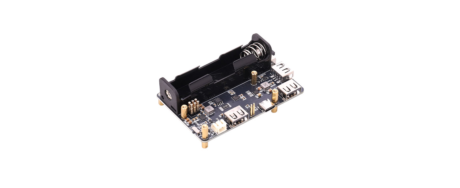
The Pi Zero UPS USB HUB is an uninterrupted power supply (UPS) expansion board designed specifically for the Raspberry Pi Zero series. It combines efficient power management and USB expansion functionality, providing a stable and reliable power source that ensures continuous system operation during power interruptions.
The compact board integrates an 18650 battery holder and an external lithium battery connector, supporting flexible battery configuration options. With intuitive battery level and charging status indicators, users can easily monitor real-time power conditions.
Additionally, it features three USB 2.0 ports, allowing users to switch between Normal USB HUB Mode and Pi Zero USB HUB Mode via a hardware toggle switch. Its built-in reverse-polarity protection prevents battery connection errors, ensuring safe operation.
This module provides Raspberry Pi Zero developers with an efficient and dependable power and expansion solution.
II Product Features
- Uninterrupted Power Supply: Onboard power-path management chip enables rapid charge/discharge switching for seamless power transition.
- USB Expansion Function: Three USB 2.0 Type-A ports with selectable Normal USB HUB Mode or Pi Zero USB HUB Mode.
- Battery Level Display: Onboard LED driver chip provides intuitive four-segment battery level indication.
- Power Monitoring: Integrated boost converter and battery monitoring chip (INA219) enable real-time monitoring of voltage, current, and power, ensuring a stable 5 V output.
Ⅲ Product Parameters
Item | Specification |
Model | Pi Zero UPS USB HUB |
USB Interface | 3 × USB 2.0 |
Battery Monitoring Chip | INA219 |
Communication Interface | I²C |
Battery Interface | 18650 battery holder and PH2.0 2-pin 3.7 V lithium battery connector |
Output Voltage | 5 V |
Mounting Hole Diameter | 2.5 mm |
Dimensions | 87 mm (L) × 57 mm (W) |
Resource Overview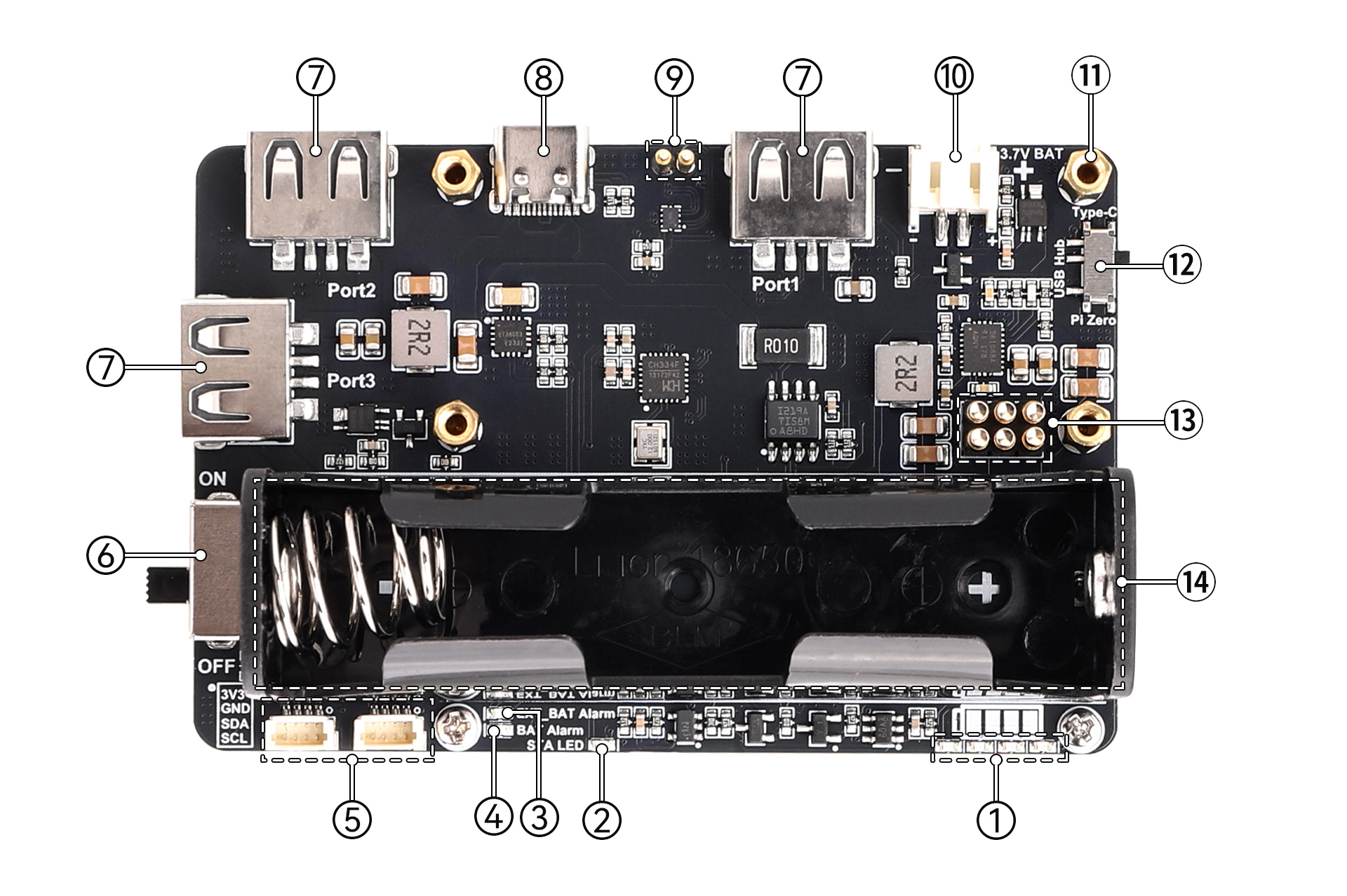
① Battery Capacity Indicator
② Charging Status Indicator
③ External Battery Reverse Polarity Warning LED: When the battery connected to connector ⑩ is connected with reversed polarity, this warning LED will turn on.
④ Battery Reverse Polarity Warning LED: When the battery installed in the battery holder ⑭ is inserted with reversed polarity, this warning LED will turn on.
⑤ 1.0 mm Pitch 4-Pin I2C Connector: Breaks out the Pi Zero's 3V3, GND, SDA.1, and SCL.1 pins.
⑥ Power Switch
⑦ USB 2.0 Type-A Female Port
⑧ Type-C Connector: Supports 5V power input and USB HUB function.
⑨ USB HUB Pogo Pins
⑩ PH2.0 2-Pin 3.7V Lithium Battery Expansion Connector: Pay attention to the positive and negative polarity when connecting the battery.
⑪ M2.5 Mounting Hole
⑫ Function Mode Switch: Used to switch between standard USB HUB mode and Pi Zero USB HUB mode.
⑬ Power & Communication Pins
⑭ 18650 Battery Holder: Supports installation of a protected 3.7V lithium battery. Pay attention to the positive and negative polarity when installing the battery.
IV Usage
4.1 Hardware Description
During hardware assembly, to ensure operational safety and hardware reliability, please strictly follow the procedures below: Before assembly, confirm that the power slide switch on the expansion board is in the "OFF" position, meaning the 5V output is disconnected. Precisely align the power & communication pins of the Raspberry Pi Zero main board with those of the expansion board. Use the included M2.5 brass standoffs and screws, tightening them in a diagonal sequence in two passes to ensure no misalignment or floating between the main board and the expansion board. Only after mechanical fixation is complete should the battery be connected to the board.
Precautions:
- Before assembly, slide the power switch to the OFF position to prevent short circuits during assembly.
- When connecting the battery, please pay attention to the polarity; do not connect it incorrectly. Do not use other inferior chargers or charging boards to charge the lithium battery.
- When using the USB 2.0 function, pay attention to setting the function toggle switch to the corresponding position.
- Place battery products properly in a dry and safe environment.
4.2 Function Introduction
- The board features 3-port USB 2.0 expansion interfaces and allows flexible use of Normal USB HUB function and Raspberry Pi Zero USB HUB function via the function toggle switch. Using the on-board USB HUB toggle switch: when the switch is set to the Pi Zero position, the Pi Zero USB HUB mode is activated, used for expanding USB 2.0 ports for the Raspberry Pi Zero; when the switch is set to the Type-C position, the Normal USB HUB mode is activated, allowing connection to a device via a Type-C data cable to expand 3 USB 2.0 ports.
| Mode Configuration | Type-C Position | Pi Zero Position |
|---|---|---|
| USB HUB | Normal USB HUB | Pi Zero USB HUB |
2. The on-board battery capacity indicator LEDs reflect the current battery voltage level. The display range is referenced in the table below:
Voltage Range (V) | LED1 | LED2 | LED3 | LED4 |
3.87V-4.2V | On | On | On | On |
3.7V-3.87V | On | On | On | Off |
3.55V-3.7V | On | On | Off | Off |
3.4V-3.55V | On | Off | Off | Off |
The 4 LEDs provide a four-stage power level display, allowing intuitive understanding of the current battery capacity status.Discharge Mode: When the power switch is ON, the remaining capacity is displayed dynamically; when OFF, the output is disconnected, and the LEDs turn off simultaneously.Charging Mode: During charging, the CHRG red indicator is constantly lit; when fully charged, the CHRG red indicator turns off; when no battery is connected and USB power is supplied, the CHRG indicator will blink.
3. Uses a spring-loaded pogo pin connection design, suitable for Raspberry Pi Zero series main boards.4. On-board reverse battery polarity protection. If the battery is reversed, the Alarm indicator will light up constantly. The battery should be removed promptly at this time, and after confirming the correct polarity direction, the battery should be correctly installed on the board.5. On-board INA219 battery monitoring chip allows real-time monitoring of the module's working status via I2C communication.6. Regarding battery charge/discharge power: The lower the battery level, the higher the charging power. The maximum USB charging power is 5W; Due to differences in connected battery models, discharge capability also varies. The maximum overall output power of the board is 9.5W.7. When using Normal USB HUB mode, set the USB HUB switch to the Type-C position, and also ensure the power switch is in the ON position.4.3 Demo Program
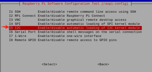
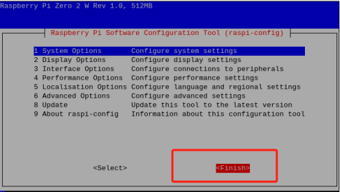
4.3.1 Raspberry Pi I2C Configuration
Start Raspberry Pi configuration:
sudo raspi-config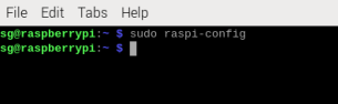
Figure 4-1
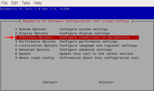
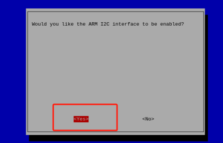
Enable the I2C interface:
Interfacing Options -> I2C -> Yes
Reboot the device:
sudo rebootScan for I2C device addresses:
sudo i2cdetect -y -a 1The correct scanned I2C address for the on-board battery monitor IC should be 0x43.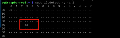
4.3.2 Example Program Demonstration
Navigate to the downloaded example program file directory, e.g.:
cd My Demo Files Directorpython INA219.pyThe window will print the current battery voltage, current, and power. When the current shows a negative value, it indicates battery discharge.
Figure 4-7
4.4 USB HUB Test
4.4.1 Raspberry Pi Zero USB HUB Function Test
Set the function toggle switch to the Pi Zero position. Correctly install the battery and the Raspberry Pi Zero. After checking that the power is normal, set the power switch to ON and start the Raspberry Pi.
Connect a keyboard, mouse, and USB flash drive to the board's USB 2.0 ports.
Refer to the following steps for testing:
Check the mount point:
lsblkAssuming the mount point is "/mut"
# Write test:
sudo dd if=/dev/zero of=/mut/testfile bs=1M count=1024 oflag=direct status=progress

# Read test:
sudo dd if=/mut/testfile of=/dev/null bs=1M count=1024 iflag=direct status=progress

# Clean up test file:
sudo rm /mut/testfile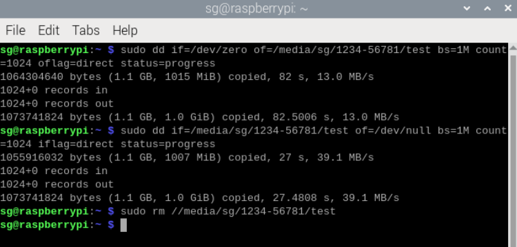
Note: Read/write speeds will vary for different storage devices due to inherent differences, leading to different performance.
4.4.2 Normal USB HUB Function Test
Set the function toggle switch to the Type-C position. Use a Type-C data cable to connect the board to a computer. The power switch also needs to be set to ON. Connect a keyboard, mouse, and USB flash drive to the board's USB 2.0 ports.
Use the command prompt to generate a 1GB cache file and manually copy and paste it to perform read/write tests, recording the data. Press Win+R, type CMD in the pop-up window to open the command prompt, then enter the command:
fsutil file createnew E:(\Your Drive Letter)\testfile.tmp 1073741824Find the generated cache file, manually copy and paste it to another location, and observe the read/write speeds.
Resources
5. Appendix
5.1 Product Precautions and Maintenance
5.1.1 Precautions
- Do not plug or unplug the module while powered on!
- Follow all warnings and guidance information marked on the product.
- Keep this product dry. If accidentally splashed or immersed by any liquid, power off immediately and allow it to dry thoroughly.
- Pay attention to ventilation and heat dissipation in the product's usage environment to avoid damage to components caused by high temperatures.
- Do not use or store this product in dusty or dirty environments.
- Do not use this product in alternating hot and cold environments to avoid condensation damaging components on the product.
- Do not handle this product roughly. Dropping, hitting, or severe shaking may damage circuits and components.
- Do not use organic solvents or corrosive liquids to clean this product.
- Do not attempt to repair or disassemble the product yourself. If the product malfunctions, please contact our company for repair in a timely manner. Unauthorized repairs may damage the product, and any damage caused thereby will not be covered under warranty.