
I Product Overview
Overview
The Solar Energy Manager B is a solar power management module supporting charging of a 3.7V 18650 lithium battery via solar panels and USB. It offers a regulated 5V/3.1A output (with the Type-C port supporting multiple protocols such as PD/QC/FCP/PE/SFCP). The module includes MPPT (Maximum Power Point Tracking) and battery charge/discharge protection, which dynamically adjusts charging power based on input voltage, maximizing solar energy utilization. The charge/discharge protection circuit monitors battery voltage to prevent overcharging and over-discharging, ensuring battery safety and longevity. Its stability and efficient charge management make it suitable for solar power generation, low-power IoT, environmental monitoring, portable power banks, and other eco-friendly projects.
1.2 Features
- Supports MPPT tracking for enhanced solar conversion efficiency.
- Supports charging through solar panels, power adapters, and USB.
- Compatible with 5V-24V solar panels, connectable via DC-002 power jack.
- Onboard MPPT SET switch to adjust to a voltage near the input voltage, improving charging efficiency.
- Provides multiple output interfaces: USB A, and USB C (Both support fast charging).
- LED indicators for monitoring battery charge/discharge status.
- Supports simultaneous charging and discharging.
- Overcharge, over-discharge, reverse polarity, and overcurrent protection circuits ensure safe and stable operation.
1.3 Specifications
Parameter | Value |
Solar Panel Input Voltage | 5-24V |
Maximum solar charging power | about 9.5W |
USB-C Max Input Current | 2.9A@5V / 2.0A@9V / 1.5A@12V |
USB-C / USB-A Max Output Current | 3.1A@5V/ 2.0A@9V/ 1.5A@12V |
Charge Cut-Off Protection Voltage | 4.2V ±1% |
Discharge Protection Voltage | 3.0V ±1% |
Solar Charging Efficiency | Approx. 77% |
USB Charging Efficiency | Up to 94% |
Boost Conversion Efficiency | Approx. 92% |
Max Standby Current (No Charge) | <20mA |
Product Dimensions | 121mm x 71mm x 25mm |
II Usage
2.1、Resource Overview
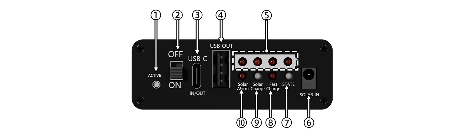
Figure 2-1 Solar Energy Manager B Resource Overview
① Output Activation Button: Activates output after low-voltage lock state.
② Power switch.
③ USB C Charging/Discharging Connector: The battery can be charged or discharged via a TYPE-C data cable, supporting multiple protocols such as PD/QC/FCP/PE/SFCP;
④ USB A Output: Supports multiple protocols such as QC, AFC, FCP, MTK PE, SCF, and SFCP.
⑤ Battery voltage indicator.
⑥ DC-002 Solar Charging Jack: Connects solar panels via power jack.
⑦ IP5356M chip status (STATE):When charging with a single USB, the red LED flashes; when discharging with a single USB (including USB-A and USB-C), this LED stays on red; when charging and discharging simultaneously, this LED flashes green at a frequency of 1Hz (including discharging when the USB is fully charged); when the board is not connected to a load and is fully charged, it stays on green.
⑧ Fast Charge: Indicator LED for fast charging function, which turns red during charging and discharging with fast charging protocol.
⑨ Solar Charge: Indicator LED for solar charging status. Red indicates that solar charging is in progress, and green indicates that solar charging is fully charged.
⑩ Solar Alarm: Indicator LED for reversed polarity of the solar charging panel (red).
2.2、Interface Description
1. Solar Panel Input Ports (see⑥in Figure 2-1): DC-002 power Jack. Users should first set the corresponding MPPT voltage according to the output voltage of the solar panel, and then connect the solar panel.
2. One USB Type-C Input/Output Port (see ③ in Figure 2-1): This port can be used to charge the battery via the USB Type-C connector or to discharge through this port. When charging the battery via USB Type-C, the module will automatically disconnect the solar panel charging. If the connected device supports fast charging protocols, the Fast Charge LED will lights up.
3. One Activation Button (see ① in Figure 2-1): When the battery voltage drops below 3V, the board enters a locked state to protect the battery. In the locked state, the board will not discharge normally. The discharge function can only be activated by entering charging mode (via Solar or Type-C charging) or by pressing the activation button. During the load discharge process, the greater the load current, the higher the battery voltage after the low-power lock is triggered. The smaller the load current, the lower the battery voltage after the low-power lock is triggered. This is because there is a certain internal resistance inside the battery (also called the internal resistance of the battery). When you connect a load, the battery current flows through the internal resistance, causing a certain voltage drop inside the battery. The magnitude of this voltage drop is related to the magnitude of the current, so the greater the load current, the more obvious the battery voltage drop, causing the battery terminal voltage to drop. When the load is removed, the internal voltage drop of the battery disappears, and the battery voltage returns to normal levels.
4. One power switch (see ② in Figure 2-1): Users can toggle it to the "OFF" state when necessary to save battery power.
2.3、Product usage
- When installing the battery and connecting the solar panel, please ensure the correct polarity and avoid reversing the connections.
- Do not directly touch the core components with your hands during operation; ensure proper static protection.

2.4、Related Instructions
1. "MPPT SET" DIP Switch (See the red arrow in Figure 2-3)Settings:When using the solar panel to charge the battery, ensure the "MPPT SET" DIP switch is correctly configured. Only one position of the DIP switch should be set to "ON," and all other positions should be set to "OFF." The voltage set by the "MPPT SET" DIP switch should be based on the specifications of the solar panel. The closer the open-circuit output voltage of the solar panel is to the MPPT-set voltage, the higher the charging efficiency. However, the output voltage of the solar panel must be greater than or equal to the MPPT-set voltage. The board is factory-set to 18V by default. Please change it to other voltage values if necessary.The charging voltage settings are shown in the figure 2-4 below:

Figure 2-3 Figure 2-4
2. Battery Charging Power in Solar Mode:The lower the battery charge, the higher the charging power.The higher the solar panel output power, the higher the charging power.When the solar panel output power is sufficient and the battery charge is low, the maximum charging power is approximately 9.5W.
3. Simultaneous Charging and Discharging:The board supports simultaneous charging and discharging, meaning it can charge via solar power while discharging or charge via USB while discharging.In the USB mode, simultaneous charging and discharging does not support fast charging, and both charging and discharging voltages are 5V. In this case, the maximum charging current is 2A.In solar mode, simultaneous charging and discharging supports fast charging.
4. Discharge status during charging:During charging, once the board is connected to a load, its output will remain constant. Even if the load is removed during this period, the green light of its STATE will continue to flash until the charging power source is removed.
5. Charging Behavior with Both Solar and USB Connections:When both the Solar and USB interfaces are charging, the charging current from the Solar interface will be disconnected, The Solar Charge LED is green. The board will prioritize USB charging.
6. Onboard LED Indicators: The definitions of the onboard LED indicators are shown in Table 2-1 below:
| Description of LED Indicators | Solar Alarm (Red) | This LED will turn on when the polarity of the Solar charging power supply is reversed. |
| Solar Charge (red-green dual-color) | This LED will turn red when Solar is charging. This LED will turn green when Solar is fully charged. | |
| Fast Charge (Red) | This LED will turn on during fast charging. | |
| STATE (red-green dual-color) | The LED on the board will flash red at a frequency of 1Hz only when the board is being charged via USB. The LED will stay red when the board is only discharging. The LED will flash green at a frequency of 1Hz during simultaneous charging and discharging (including discharging when the USB is fully charged). The LED will stay green when the board is fully charged and has no load connected. | |
| Battery voltage indicator (see ⑤ in Figure 2-1: 4 red ones) | Battery voltage indicator: the more LEDs that are lit from left to right, the higher the battery voltage; conversely, the fewer the LEDs, the lower the voltage. |
7.Battery Usage Instructions:Users should use batteries of the same specification and ensure the voltage difference between individual batteries is within 0.2V. If the voltage of each battery cannot be measured directly, you may charge only one battery at a time until it is fully charged, remove it, then charge the next battery in the same way. Finally, install all fully charged batteries together into the multi-cell battery holder for use.
8. The default function of the product is that once a load is connected, the output will remain active, and the battery voltage indicator will remain lit (provided that the battery is sufficiently charged). Even if you remove the load during use, the board will not automatically enter sleep mode. At this point, you can press the output activation button on the board (indicated as ① in Figure 2-1) to allow the board to enter sleep mode (the STATE and voltage indicator will turn off). This way, you can significantly extend the standby time of the board. If you do not use it for an extended period, it is recommended to switch the power to the 'OFF' position.
If you want the board to automatically enter sleep mode after removing the load without having to press the activation button, you can choose to download the following program into the STM32F030 chip on the board (you can refer to the schematic). Of course, you will need to prepare a programmer yourself, such as ST-LINK, as well as the corresponding programming software, such as ST-LINK Utility. The board exposes the SWD debugging interface pins SWDIO, SWCLK, and GND (as shown by the red arrows in Figure 2-5, from left to right are CLK, DIO, GND). While the board is activated, you can connect the board and the programmer using DuPont wires, and then program the STM32F030.You can choose to download different programs based on the actual load power situation. The factory default program burned is 0-current-unit-level.hex, where the first digit of the program name represents the current unit level that causes the board to automatically enter sleep mode under light load. The smaller this number is, the better the board can continuously supply power to small loads without automatically entering sleep mode. For example, if you have a load that consumes 50mA, the factory default program will not cause it to automatically enter sleep mode when you remove that load. At this point, you can sequentially choose to program 1-current-unit-level.hex, 2-current-unit-level.hex, 3-current-unit-level.hex, until you meet the requirement of "automatically entering sleep mode after removing the load." If you have programmed the 3-current-unit-level.hex program, then if you connect a load of 10mA afterward, the board may stop supplying power to the load and enter sleep mode after a few seconds.

Ⅴ Resources
data sheet