
Product Overview
This product is a 7.5-inch black-and-white e-ink display expansion module with a screen resolution of 800x480. It uses SPI communication and supports both full and partial refresh modes. The driver board is designed based on the 40-pin interface of Raspberry Pi, making it compatible with Raspberry Pi series boards. We provide example programs in C and Python for Raspberry Pi. A reserved SPI control interface allows easy integration with main control boards such as Arduino, STM32, and ESP32. We also offer example code for Arduino, STM32, and ESP32, which supports displaying images, English and numerical characters, and drawing points, lines, rectangles, and circles.
Product Specifications
| Pixels | 800 x 480 |
| Display Colors | Monochrome (Black and White) |
| Gray Levels | 2 |
| Level-Shifting Chip | TXS0108EPWR |
| Signal Interface | SPI |
| Power Supply Voltage | 3.3V/5V |
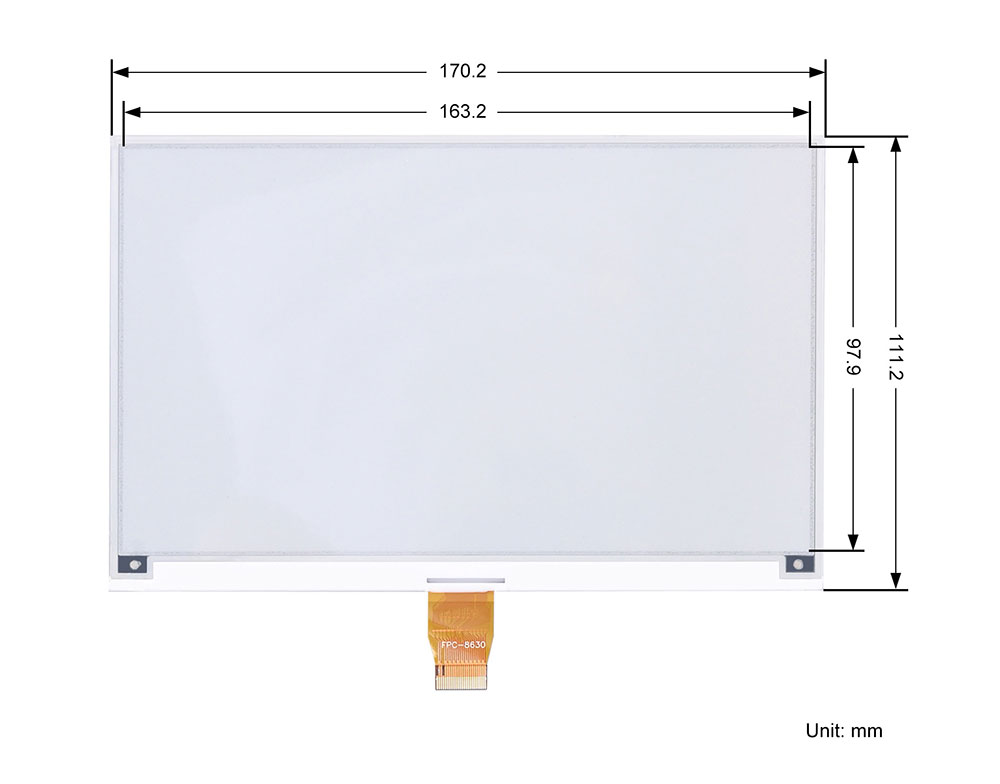
| Display Area | 163.2mm x 97.9mm |
| Partial Refresh | 0.3s (4-wire SPI mode) |
| Full Refresh | 3s (4-wire SPI mode) |
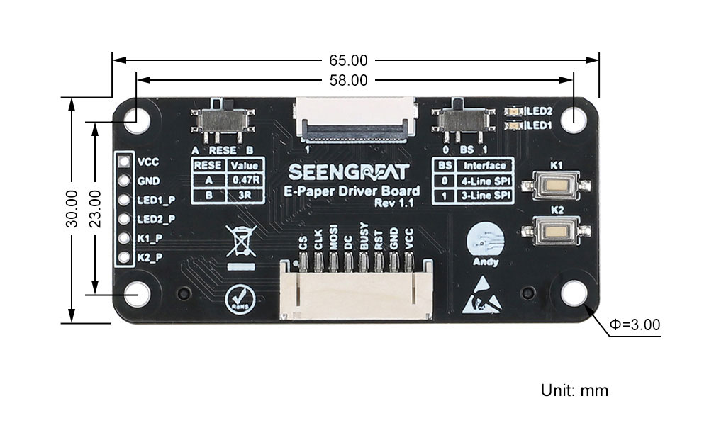
| Dimensions | Screen: 170.2mm x 111.2mm, Driver Board: 65mm (length) x 30mm (width) |
| Weight | 135g (net weight 55g) |
Interface Definition
| VCC | 3.3V/5V |
| GND | Power ground |
| RST | External reset pin (low level reset) |
| BUSY | Busy status output pin |
| D/C | Data/Command control pin (high level for data, low level for command) |
| MOSI | SPI communication MOSI pin |
| CS | SPI chip select pin (active low) |
| CLK | SPI communication SCK pin |
| LED1_P | LED1 control pin |
| LED2_P | LED2 control pin |
| K1_P | Button K1 control pin |
| K2_P | Button K2 control pin |
Usage
All example programs provided for this product are based on the 4-wire SPI mode, so the BS selection switch on the board is defaulted to the "0" position. Additionally, the RESE switch is defaulted to position A; setting it to position B may result in abnormal display.
Resource Overview
The overview of the driver resources is shown in the figure below:
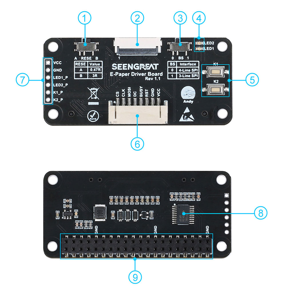
② E-paper screen connector
③ SPI lines count selection switch(default is "0" position)
④ Two LEDs
⑤ Two buttons
⑥ SPI control interface connector
⑦ Control pins for LEDs and buttons
⑧ Level-shifting chip TXS0108
⑨ Raspberry Pi 40-pin GPIO interface
Raspberry Pi Example Usage
The example code for the Raspberry Pi platform is divided into two versions: lgpio and wiringpi. The bookworm system uses the lgpio library, while the bullseye system uses the wiringpi library.
Raspberry Pi Platform Interface Definition
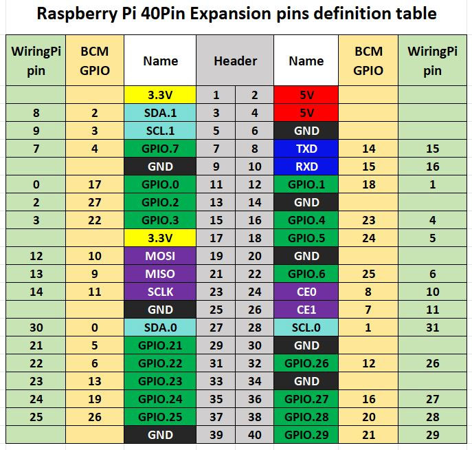
The example programs for the Raspberry Pi board use the BCM numbering for pin definitions with the lgpio library and the wiringpi numbering with the wiringpi library. The pin wiring definitions for the Raspberry Pi board are as shown in the table below:
| E-paper Interface (E-paper Connector) | Pin Function | BCM Numbering | wiringpi Numbering |
|---|---|---|---|
| VCC | 3.3V | ||
| GND | GND | ||
| BUSY | Busy Signal Pin | 24 | 5 |
| RSTN | Reset | 17 | 0 |
| D/C | Command/Data Select | 25 | 6 |
| SDA | SPI Data Out/Slave In | 10 | 12 |
| SCL | SPI Clock | 11 | 14 |
| CSB | SPI Chip Select | 8 | 10 |
| LED1 | 4 | 7 | |
| LED2 | 18 | 1 | |
| K1 | 27 | 2 | |
| K2 | 22 | 3 |
wiringpi Library Installation
sudo apt-get install wiringpi
wget https://project-downloads.drogon.net/wiringpi-latest.deb #
Upgrade Raspberry Pi 4B Version
sudo dpkg -i wiringpi-latest.deb
gpio -v #
If version 2.52 appears, it indicates that the installation has been successful.
#For the Bullseye branch system, use the following command:
git clone https://github.com/WiringPi/WiringPi
cd WiringPi
. /build
gpio -v #
# Running "gpio -v" will show version 2.70. If it doesn't appear, it means there is an installation error.
If an error message "ImportError: No module named 'wiringpi'" appears when running a sample program in Python version, run the following command:
# For Python 2.x version
pip install wiringpi# For Python 3.x version
pip3 install wiringpiNote: If the installation fails, you can try the following compiled installation.
git clone --recursive https://github.com/WiringPi/WiringPi-Python.gitNote: The --recursive option can automatically pull submodules. Otherwise, you need to download them manually.
Enter the newly downloaded WiringPi-Python folder and use the following commands to compile and install:
# For Python 2.x version
sudo python setup.py install# For Python 3.x version
sudo python3 setup.py installIf the following error occurs:

In this case, enter the command sudo apt install swig to install SWIG. After completing the installation, run sudo python3 setup.py install to compile and install. If you see similar information, it indicates that the installation was successful.
lgpio Library Installation
For the Bookworm system, the example programs use the lgpio library. The installation command for this library is:
wget https://github.com/joan2937/lg/archive/master.zip
unzip master.zip
cd lg-master
make
sudo make install
Enable the SPI Interface
sudo raspi-configEnable the SPI Interface
Interfacing Options -> SPI -> YesCheck the enabled SPI devices:
Is /dev/spi* #This will print: "/dev/spidev0.0" and "/dev/spidev0.1"
Python Library Installation
The example program uses the Python 3 environment. To run the Python example program, you need to install the PIL, numpy, and spidev libraries. Enter the following commands to install them:
sudo apt-get install python3-pil
sudo apt-get install python3-numpy
sudo apt-get install python3-pip
sudo pip3 install spidev
C Version Example
Using the lgpio library as an example, navigate to the /demo codes/raspberry_pi/lgpio/c directory:
sudo make clean
sudo make
sudo ./main
After entering the above commands, you can observe the e-paper display.
Python Version Example
Using the lgpio library as an example, navigate to the /demo codes/raspberry_pi/lgpio/python directory.
sudo python3 gui_demo.pyAfter entering the above commands, you can observe the e-paper display.
Arduino Example Usage
Hardware Interface Configuration
Table 2-2 shows the wiring definitions between the Arduino Mega and the e-paper display.
| E-paper Interface | Arduino Mega |
|---|---|
| VCC | 5V |
| GND | GND |
| CS | D53 |
| CLK | D52 |
| MOSI | D51 |
| DC | D8 |
| RST | D9 |
| BUSY | D10 |
Table 2-3 E-paper Display and Arduino UNO Pin Definitions
| E-paper Interface | Arduino UNO |
|---|---|
| VCC | 5V |
| GND | GND |
| CS | D7 |
| CLK | D13 |
| MOSI | D11 |
| DC | D10 |
| RST | D9 |
| BUSY | D8 |
Example Usage
Open the project file /demo codes/Arduino_MEGA/Arduino_MEGA.ino or /demo codes/Arduino_UNO/Arduino_UNO.ino in the Arduino IDE. Select the correct Board and Port based on your setup. Click Verify, and once the verification is successful, upload it to the module. Observe the e-paper display.
STM32 Example Usage
The example code is based on STM32F103C8T6.
Hardware Interface Configuration
| E-paper Interface | STM32 Interface |
|---|---|
| VCC | 3.3V |
| GND | GND |
| CS | PB12 |
| CLK | PB13 |
| MOSI | PB15 |
| DC | PA8 |
| RST | PA11 |
| BUSY | PA12 |
Example Usage
Open the example in the directory /demo codes/STM32 using Keil uVision5 software. After compiling without errors, download it to the module and observe the e-paper display.
ESP32 Example Usage
The example program uses the ESP32 module ESP32-WROOM-32E.
Hardware Interface Configuration
| E-paper Interface | ESP32 Interface |
|---|---|
| VCC | 3.3V |
| GND | GND |
| CS | IO27 |
| CLK | IO18 |
| MOSI | IO23 |
| DC | IO14 |
| RST | IO33 |
| BUSY | IO13 |
Example Usage
Open the project file /demo codes/Arduino_ESP32 using the Arduino IDE. Select the correct Board and Port based on your setup. Click Verify, and once the verification is successful, upload it to the module and observe the e-paper display.
Image Creation and Mode Extraction
Image Creation
Create images with a resolution of 800 x 480 in pure black and white (grayscale is not supported). Save them as BMP or JPG files (BMP format is recommended). Due to limited memory on some MCU platforms, images may need to be smaller on these platforms, for example, 400 x 240 for Arduino.
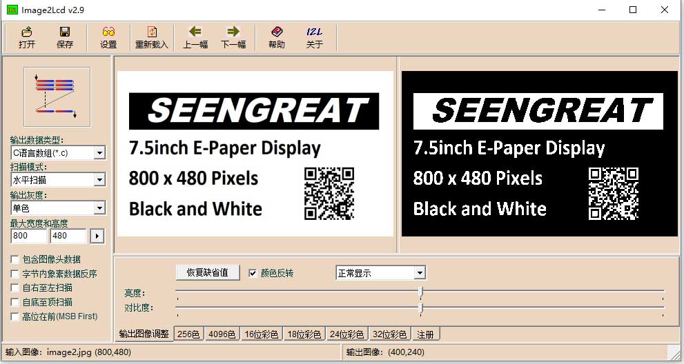
Mode Extraction
You can use the image2lcd software for mode extraction. This software is provided in the compressed package. To achieve the effect shown in Figure 2-2, follow the mode extraction parameter settings as shown in Figure 2-3:
1 Open the image that needs to be extracted.
2 Output data type: Select "C language array (*.c)".
3 Scanning method: Select "Horizontal scan".
4 Output grayscale: Select "Monochrome".
5 Maximum width and height: Choose "800" and "480", then click the arrow to confirm.
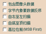
6 Ensure that none of the following 5 items are checked.
7 Color Inversion: Select according to the actual situation.
8 Click "Save" to store the converted array in a file with the ".c" extension. For an image with a resolution of 800 x 480 in pure black and white, a 48,000-byte image array will be generated.
9 Finally, replace the corresponding array in the example program code with the array from the ".c" file.
Resources
Related Links
Python Image Library
For additional features, users can visit the official website to learn more: https://pillow.readthedocs.io/en/latest/handbook/index.html