Product Overview
This product is a single-channel relay Raspberry Pi expansion board, compatible with Raspberry Pi Zero/Zero W/Zero WH/2B/3B/3B+/4B, STM32, ESP32, Arduino, and more. It features onboard optocoupler isolation and level-shifting circuits, making it compatible with 3.3V and 5V systems.
Product Features
- Power Supply Voltage: 3.3V/5V
- Relay Load Capacity: NO: 10A 250VAC/28VDC; NO/NC 5A 250VAC
- Relay Operation Indicator LED: Allows easy monitoring of relay status
- Optocoupler Isolation Circuit: Strong anti-interference capability, stable operation
- Open-source Example Programs: Provided for Raspberry Pi and Arduino development boards
Product Specifications
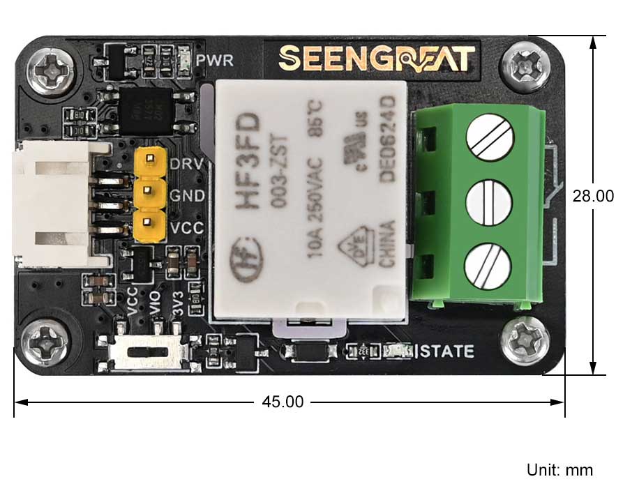
| Dimensions | 45mm (Length) * 28mm (Width) |
| Weight | 100g (Net Weight: 21g) |
| Power Supply Voltage | 3.3V/5V |
| Optocoupler | LTV-357T-B-IN |
| Trigger Level | Low-level Trigger |
Usage
The relay control pin DRV is triggered by a low level. When the VCC supply voltage is 3.3V and the DRV pin's logic level is 0V and 3.3V, the VIO switch can be set to the VCC or 3V3 position. If the VCC supply voltage is 5V and the DRV pin's logic level is 0V and 3.3V, the VIO switch should also be set to the 3V3 position. However, if the logic level is 0V and 5V, the VIO switch should be set to the VCC position. The corresponding states of the switch for different VCC and DRV pin drive voltages are shown in Table 2-1 below:
| VCC Voltage | DRV Signal Level | VIO Switch Position |
|---|---|---|
| 3.3V | 0~3.3V | VCC/3V3 |
| 5V | 0~5V | VCC |
| 5V | 0~3.3V | 3V3 |
Module Resources Overview
The resource overview is shown in the diagram below:
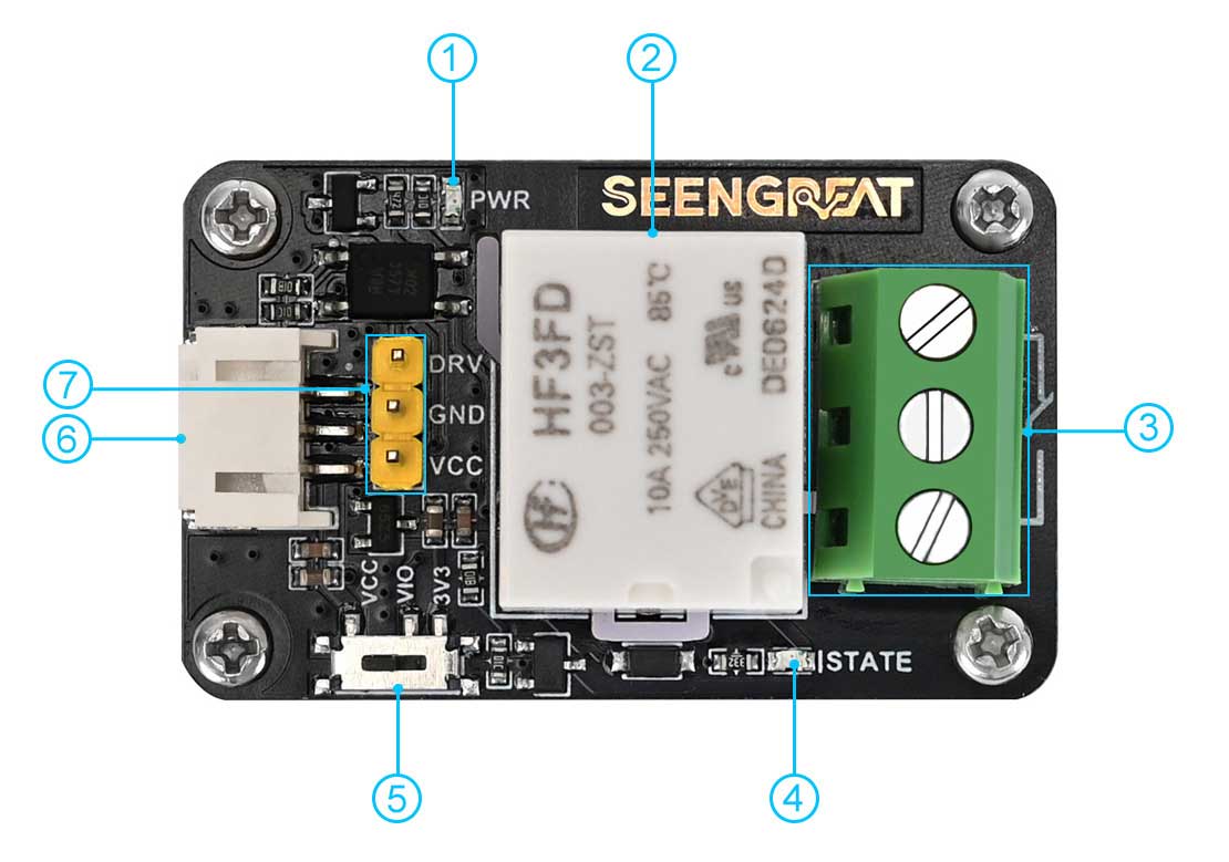
1. Power Indicator LED
2. Relay
3. Relay Output Terminals
4. Relay Working Indicator LED: The LED is on when the relay's normally open (NO) terminal is closed and the normally closed (NC) terminal is open. The LED is off when the NO terminal is open and the NC terminal is closed.
5. Relay Control Signal Level Selection Switch: Can be set to VCC or 3V3
6. PH2.0 1x3P Connector
7. 2.54mm 1x3P Pin Header
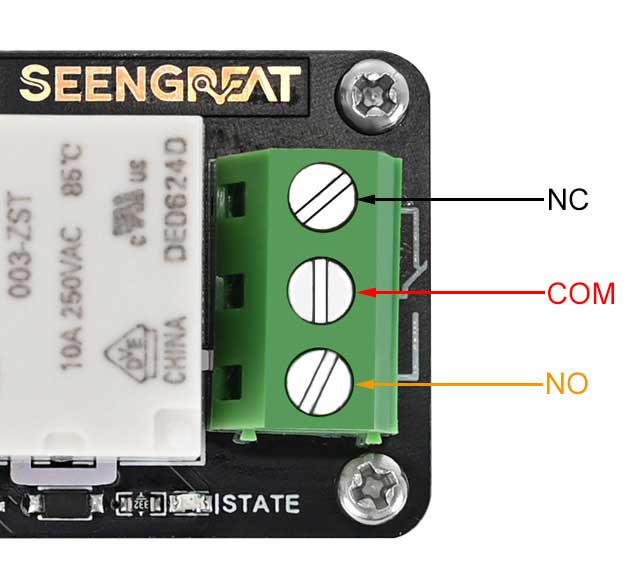
Relay Wiring Diagram is as follows:
Raspberry Pi Platform Example Program Usage
The example code is available in two versions: one for the WiringPi library and one for the Lgpio library. The Bullseye system uses the WiringPi library, while the Bookworm system uses the Lgpio library.
Wiring Definition
In the Raspberry Pi mainboard, the example program for the Bookworm system uses BCM numbering for pin definitions, while the Bullseye system uses WiringPi numbering. The pin wiring definitions for the Raspberry Pi mainboard are as shown in the table below:
| Expansion Board Interface | Pin Function | BCM numbering | WiringPi numbering |
|---|---|---|---|
| VCC | 3.3V | 3.3V | 3.3V |
| GND | GND | GND | GND |
| DRV | Relay Trigger Pin | 26 | P25 |
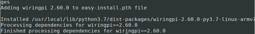
WiringPi Library Installation
sudo apt-get install wiringpi
wget https://project-downloads.drogon.net/wiringpi-latest.deb #
Raspberry Pi 4B Version Upgrade
sudo dpkg -i wiringpi-latest.deb
gpio -v #
If version 2.52 appears, it indicates that the installation was successful.
# For the Bullseye branch system, use the following commands:
git clone https://github.com/WiringPi/WiringPi
cd WiringPi
. /build
gpio -v #
# Running gpio -v should display version 2.70. If it does not, it indicates that the installation is incorrect.
If you encounter the error "ImportError: No module named 'wiringpi'" when running Python example programs, use the following command:
# For Python 2.x version
pip install wiringpi# For Python 3.x version
pip3 install wiringpiNote: If the installation fails, you can try the following compilation and installation steps:
git clone --recursive https://github.com/WiringPi/WiringPi-Python.gitNote: The --recursive option automatically pulls submodules; otherwise, you will need to download them manually.
Navigate to the downloaded WiringPi-Python folder and enter the following commands to compile and install:
# For Python 2.x version
sudo python setup.py install# For Python 3.x version
sudo python3 setup.py installIf you encounter the following error:

If you encounter the error, enter the command sudo apt install swig to install SWIG. After installation, run sudo python3 setup.py install to compile and install. If you see similar information, it indicates that the installation was successful.
Lgpio Library Installation
For the Bookworm system, the example program uses the Lgpio library. The installation command for this library is as follows:
wget https://github.com/joan2937/lg/archive/master.zip
unzip master.zip
cd lg-master
make
sudo make install
Run Example Program
Python:
Enter the Python directory:
cd /home/pi/raspberry-pi/relay-lgpio/pythonor
cd /home/pi/raspberry-pi/relay-wiringpi/pythonExecute:
sudo python3 relay.pyC:
Enter the C directory:
cd /home/pi/raspberry-pi/relay-lgpio/cor
cd /home/pi/raspberry-pi/relay-wiringpi/cExecute:
sudo make clean
sudo make
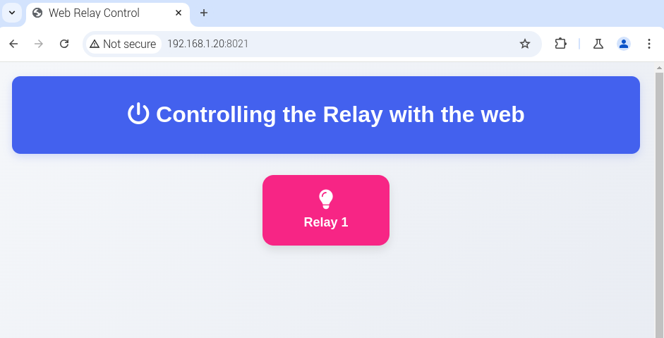
sudo ./mainWeb control
The web control of this example is based on the python Web framework to control the relay.Enter the Linux terminal and execute the following command in the terminal:
sudo apt-get install python3-bottle
cd python-bottle
sudo python3 main.py
Enter the Raspberry Pi IP address and port number 8021 in the address bar of Google Chrome (other browsers may not be compatible)
 Arduino Platform Example Program Usage
Wiring Definition
The wiring definitions for connecting the module to the Arduino UNO mainboard are shown in the table below:
| Pin Interface | Arduino UNO |
|---|---|
| VCC | 5V |
| GND | GND |
| DRV | D7 |
Run Example Program
After wiring according to Table 2-3, open the project file demo codes\Arduino\relay.ino using the Arduino IDE. Then, select Arduino Uno in Tools -> Board and the corresponding port in Tools -> Port. Click Verify to check for errors, and if verification is successful, upload the code to the Arduino Uno. Observe the relay status.
Resources
Datasheet