Product Overview
This product is a universal SPI E-Ink display bare-board driver, suitable for Raspberry Pi series mainboards, Arduino, STM32, ESP32 and more. It comes equipped with an E-Ink screen adapter board and a flexible flat cable (FPC) for driving various sizes of E-Ink screens. We provide C and Python example code for Raspberry Pi, as well as ESP32, Arduino and STM32 example codes. These example codes enable drawing points, lines, rectangles, circles, displaying English alphanumeric characters, and images on the E-Ink screen.
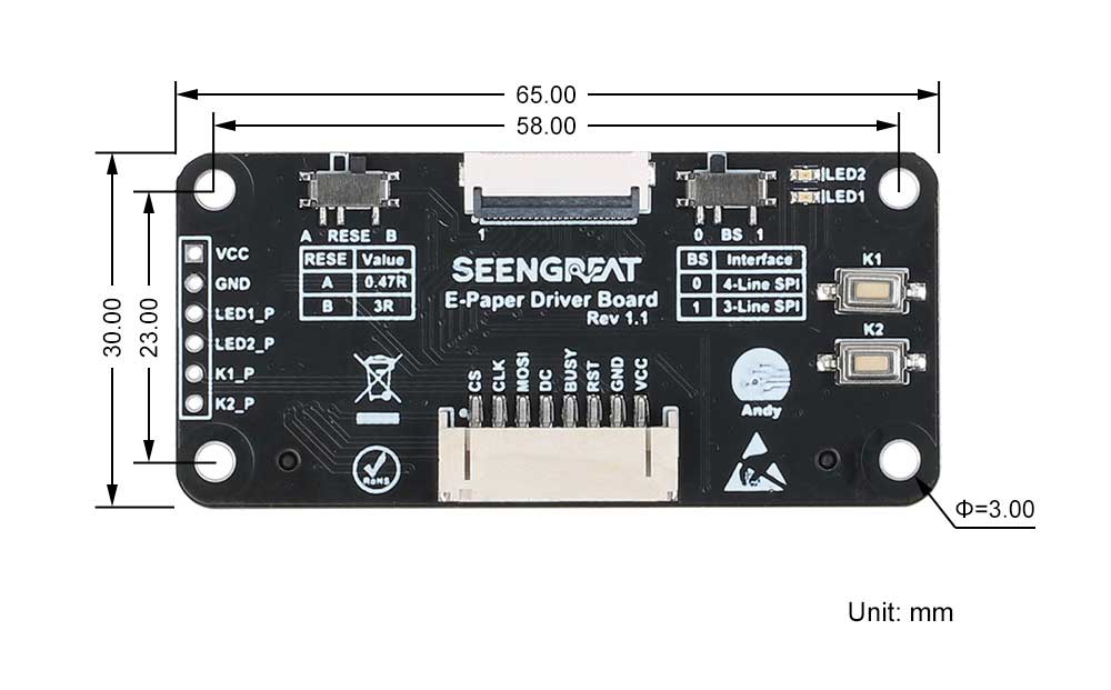
Product Specifications
| Dimensions | 65mm (length) x 30mm (width) |
| Mounting Hole Spacing | 58mm (length) x 23mm (width) |
| Level-Shifting Chip | TXS0108EPWR |
| Communication Interfaces | SPI |
| Supply Voltage | 5V/3.3V |
| Mounting Hole Diameter | 3mm |
Compatible E-Ink Screen Models
| Model | Color | Grayscale | Resolution | Display area Size (mm) | Dimensions (mm) | Full Refresh Time | Partial Refresh Time |
|---|---|---|---|---|---|---|---|
| 1.54inch E-Ink | Black and White | 2 | 200x200 | 27(H)x27(W) | 37.32(W)x31.8(H) | 2S | 0.26S |
| 1.54inch E-paper RBW | Red, Black and White | 2 | 200x200 | 27(H)x27(W) | 37.32(W)x31.8(H) | 16s | nonsupport |
| 2.13inch E-paper | Black and White | 4 | 250x122 | 48.55(W)x23.7(H) | 59.2(W)x29.2(H) | 3s | 0.42s |
| 2.13inch E-paper RBW | Red, Black and White | 2 | 250x122 | 48.55(W)x23.7(H) | 59.2(W)x29.2(H) | 22s | 1.8s |
| 2.7inch E-paper | Black and White | 4 | 264x176 | 57.29(W)x38.19(H) | 70.42(W)x45.8(H) | 3s | 0.42s |
| 2.9inch E-paper | Black and White | 4 | 296x128 | 66.896(W)x29.056(H) | 79(W)x36.7(H) | 3s | 0.3s |
| 4.2inch E-paper | Black and White | 4 | 400x300 | 84.8(W)x63.6(H) | 91(W)x77(H) | 3s | 0.26s |
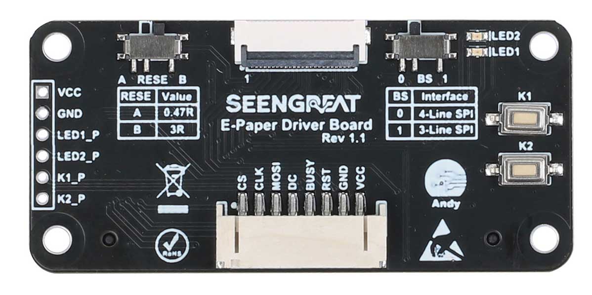
Pin Definitions
| VCC | 3.3V&5V |
| GND | Ground |
| RST | External reset pin (active low) |
| BUSY | Busy status output pin |
| D/C | Data/Command control pin (high level for data, low level for command) |
| MOSI | SPI communication MOSI pin |
| CS | SPI chip select pin (active low) |
| CLK | SPI communication SCK pin |
| LED1_P | LED1 control pin |
| LED2_P | LED2 control pin |
| K1_P | Control pin for button K1 |
| K2_P | Control pin for button K2 |
Usage
Precautions for using the E-Paper
- Avoid direct sunlight. Electronic paper will display particles under strong light, that is, the charged particles in the microcapsules will dry out under strong light, and then lose their activity and cannot be refreshed. This condition is irreversible. At the same time, moisture-proof and waterproof measures must be taken, and the operation should be strictly in accordance with the temperature and humidity range required by the specification. If the electronic paper is not used for a long time, it needs to be placed upside down, and the screen should be placed with a full white screen.
- After the electronic paper is refreshed, you need to set the sleep mode, or turn off the power after setting the sleep mode. The refresh interval of the SPI serial port electronic paper is at least 180s, especially for large-sized electronic paper, if the interval is too short, afterimages will appear, which will affect the display effect of the electronic paper.
- In order to reduce afterimages, it is recommended to add black and white full-screen refresh display after 5 partial refreshes, and increase the refresh interval.
- If the E-Paper is not refreshed for a long time, it must be powered off or enter the deep sleep mode.
- The EPD Panel / Module is manufactured from fragile materials such as glass and plastic, and may be broken or cracked if dropped. Please handle with care. Do not apply force such as bending or twisting to the EPD panel .
- High temperature, high humidity, sunlight or fluorescent light may degrade the EPD panel's performance. Please do not expose the unprotected EPD panel to high temperature, high humidity, sunlight, or fluorescent for long periods of time. Please store the EPD panel in controllable environment of warehouse and original package.
Introduction to General Configuration Resources
Resource introduction as shown in the following figure:
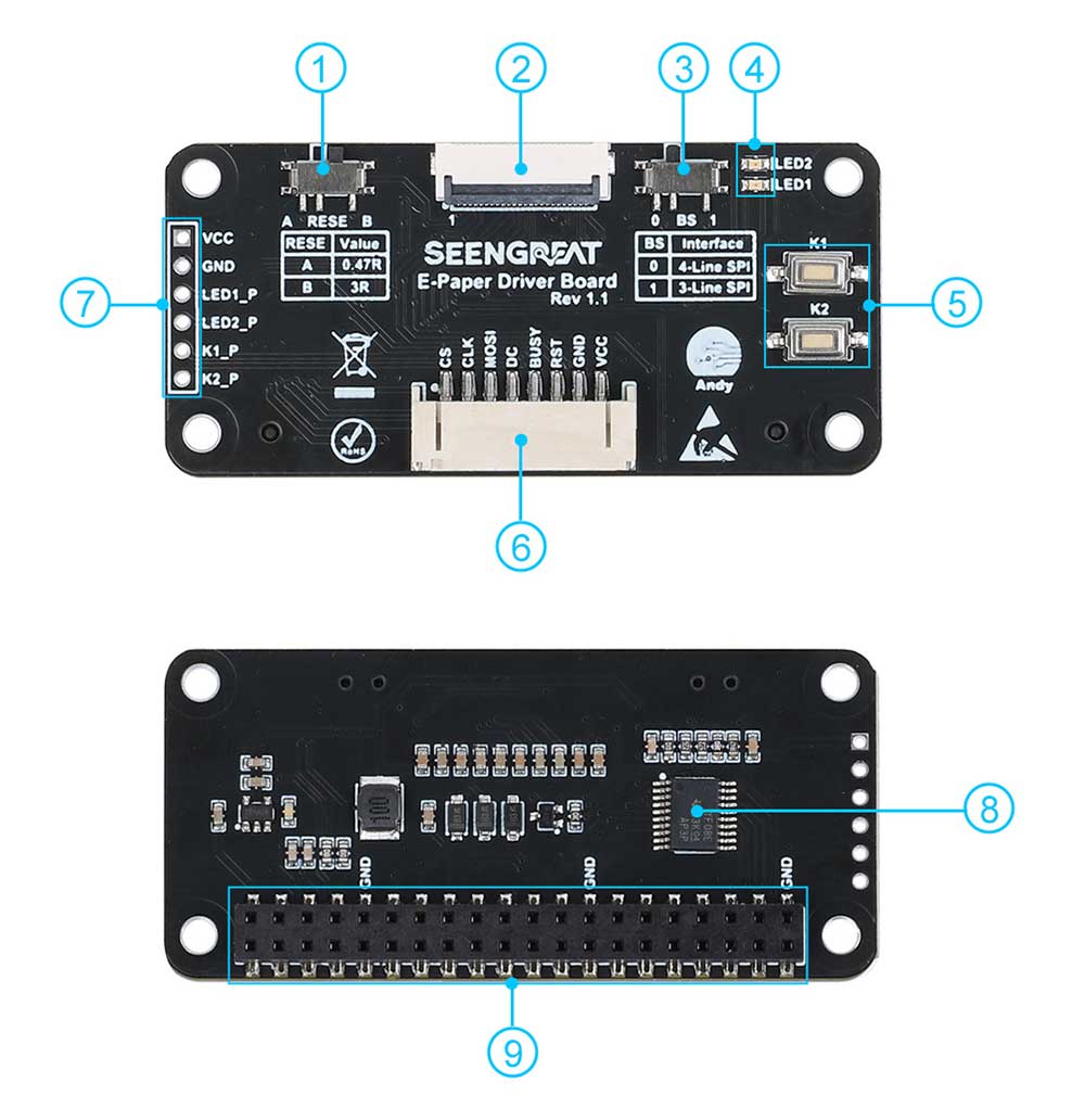
① Matching Resistor Selection Switch (RESE Switch)
② E-Ink Screen Connector
③ SPI Line Number Selection Switch (BS Switch)
④ Two LEDs
⑤ Two Buttons
⑥ SPI Control Interface Connector
⑦ Control Pins for LEDs and Buttons
⑧ Level-Shifting Chip TXS0108
⑨ Raspberry Pi 40-pin GPIO Interface Female Header
BS Switch Explanation
When the switch is set to "0," it operates in 4-line SPI mode.
When the switch is set to "1," it operates in 3-line SPI mode.
Note: All the example programs provided for this product are based on the 4-line SPI mode. Therefore, the BS switch on the board defaults to the "0" position.
RESE Switch Explanation
The RESE switch is designed to drive different sizes of E-Ink screens. Depending on the E-Ink screen being used, you should set the switch as follows:
| Setting the switch to "B" allows you to drive the specified E-Ink screen model. | Setting the switch to "A" allows you to drive the specified E-Ink screen model. |
| 1.54inch E-paper | |
| 1.54inch E-paper RBW | |
| 2.13inch E-paper | |
| 2.13inch E-paper RBW | |
| 2.7inch E-paper | |
| 2.9inch E-paper | |
| 4.2inch E-paper |
Note: If you find that the display is abnormal, you can switch to the other end. This e-paper driver board will support more e-paper display models in the future, please stay tuned!
Installation Notes
When users need to install this driver board on a Raspberry Pi, if the Raspberry Pi motherboard has a POE pin header or a higher heat sink has been installed, please use the 2.54mm 2x20P female header included in the accessory to raise it before installation. , to avoid causing signal interference or short circuit problems.
Raspberry Pi Example Program Usage
Since the bookworm system no longer supports the wiringpi library, the example program for this system uses the lgpio library, and for the bullseye system, the wiringpi library version of the example program can be used.
Raspberry Pi Platform Interface Definition
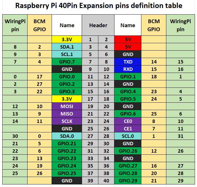
The bullseye system example program for the Raspberry Pi uses the pin definitions number in wiringPi, and the bookworm system uses the pin definition of the BCM number. The definition of the wiring with the Raspberry Pi motherboard is shown in the following table:
| E-Ink Screen Interface | wiringPi number | BCM number |
|---|---|---|
| VCC | 3.3V | 3.3V |
| GND | GND | GND |
| RST | P0 | 17 |
| BUSY | P5 | 24 |
| D/C | P6 | 25 |
| MOSI | MOSI/P12 | 10 |
| CLK | SCLK/P14 | 11 |
| CS | CE0/P10 | 8 |
| LED1 | P7 | 4 |
| LED2 | P1 | 18 |
| K1 | P2 | 27 |
| K2 | P3 | 22 |
WiringPi Library Installation
C:
sudo apt-get install wiringpi
wget https://project-downloads.drogon.net/wiringpi-latest.deb # Raspberry Pi 4B version upgrade
sudo dpkg -i wiringpi-latest.deb
gpio -v # If version 2.52 appears, the installation is successful
#For Python 2. x version
pip install wiringpi#For Python version 3. X
pip3 install wiringpiNote: If the installation fails, you can try the following compilation and installation:
git clone --recursive https://github.com/WiringPi/WiringPi-Python.gitNote: The -- recursive option can automatically pull the submodule, otherwise you need to download it manually.
Enter the WiringPi Python folder you just downloaded, enter the following command, compile and install:
#For Python 2. x version
sudo python setup.py install#For Python version 3. X
sudo python3 setup.py installIf the following error occurs:

At this point, enter the command 'sudo apt-install-swig' to install swig. Then, compile and install 'sudo python3 setup.py install'. If you see a message similar to the following, the installation was successful.
Lgpio library installation
For the bookworm system, the example program uses the lgpio library, which is installed using the following command:
wget https://github.com/joan2937/lg/archive/master.zip
unzip master.zip
cd lg-master
make
sudo make install
Enable SPI Interface
sudo raspi-configEnable SPI Interface:
Interfacing Options->SPI->YesTo check the enabled SPI devices:
ls /dev/spi*This will print:"/dev/spidev0.0"和"/dev/spidev0.1"
Python Library Installation
The example programs use the Python 3 environment. To run the python example programs, you need to install the pil, numpy, and spidev libraries. Install them one by one using the following commands:
sudo apt-get install python3-pil
sudo apt-get install python3-numpy
sudo apt-get install python3-pip
sudo apt-get install spidev
C Version Example Programs
Navigate to the C directory of the example program project files.
sudo make clean
sudo make
sudo ./main
After entering the above command, you can observe the E-Ink screen's display status.
Python Version Example Programs
Navigate to the Python directory of the example program project files. Run the following command:
python3 gui_demo.pyAfter entering the above command, you can observe the E-Ink screen's display status.
Arduino Example Program Usage
Hardware Interface Configuration Instructions
Table 2-2 is the wiring definition between Arduino Mega and e-ink screen:
| E-Ink Screen Interface | Arduino Mega |
|---|---|
| VCC | 5V |
| GND | GND |
| RST | D9 |
| BUSY | D10 |
| D/C | D8 |
| MOSI | D51 |
| CLK | D52 |
| CS | D53 |
Table 2-3 is the wiring definition between Arduino Uno and e-ink screen:
| E-Ink Screen Interface | Arduino Interface |
|---|---|
| VCC | 5V |
| GND | GND |
| RST | D9 |
| BUSY | D8 |
| D/C | D10 |
| MOSI | D13 |
| CLK | D12 |
| CS | D11 |
Example Program Usage
Open the project's example program file using the Arduino IDE software. Click on the "Verify" button to check for any errors, and once it verifies successfully, upload it to the module. Observe the E-Ink screen's display status.
STM32 Example Program Usage
The STM32 module used in this example program is STM32F103C8T6.
Hardware Interface Configuration Instructions
| E-Ink Screen Interface | STM32 Interface |
|---|---|
| VCC | 3.3V |
| GND | GND |
| RST | PA11 |
| BUSY | PA12 |
| D/C | PA8 |
| MOSI | PB15 |
| CLK | PB13 |
| CS | PB12 |
Example Program Usage
Open the example program project file using Keil uVision5 software. After compiling without errors, download it to the module. Observe the E-Ink screen's display status.
ESP32 Example Program Usage
The ESP32 module used in this example program is ESP32-WROOM-32E.
Hardware Interface Configuration Instructions
| E-Ink Screen Interface | ESP32 |
|---|---|
| VCC | 3.3V |
| GND | GND |
| CS | IO27 |
| CLK | IO18 |
| MOSI | IO23 |
| DC | IO14 |
| RST | IO33 |
| BUSY | IO13 |
Example Program Usage
Open the project's example program file using the Arduino IDE software. Click on the "Verify" button to check for any errors, and once it verifies successfully, upload it to the module. Observe the E-Ink screen's display status.
Black and White Image Creation and Modeling Instructions
Image Creation
Create a black and white image with the resolution corresponding to the e-ink display model you are using (for example, if using a 1.54-inch black and white e-ink display, you need to create a pure black and white image with a resolution of 200 x 200 pixels, as grayscale is not supported). For the resolutions of compatible e-ink display sizes, please refer to the compatible e-ink display model table above. Save the image as a BMP or JPG file (BMP format is recommended).
Modeling
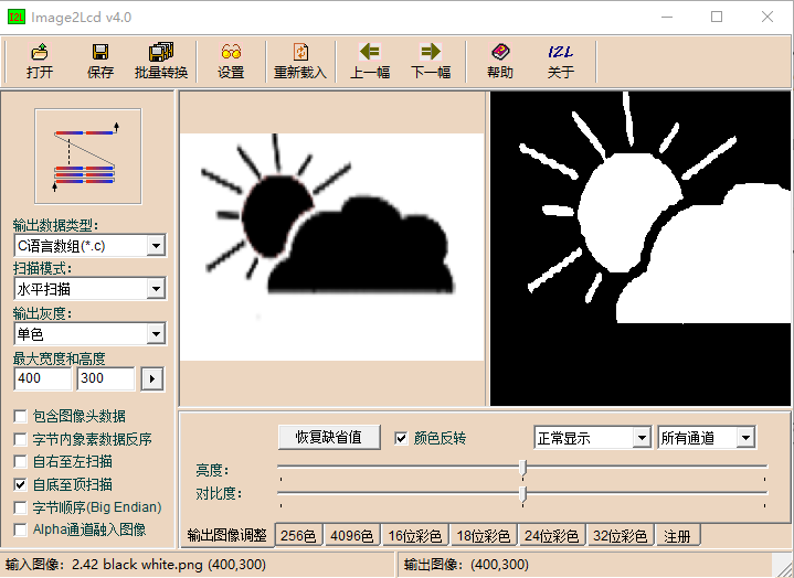
You can use the image2lcd software for image conversion. This software is provided in the compressed package. For example, when using a 1.54inch e-ink display, refer to Figure 2-2 for the parameter settings in the image conversion interface for a standard e-ink display. The method for a 4.2inch e-ink display is different; refer to Figure 2-3 for its parameter settings interface.
1.Open the image you want to model.
2.Output Data Type: Select "C Language Array (*.c)".
3.Scanning Mode: Choose "Vertical Scanning"(choose "Horizontal Scanning" for 4.2 inch e-ink display).
4. Output Gray Scale: Select "Monochrome".
5. Maximum Width and Height: Fill in the resolution based on the E-Ink screen model you are using (for example, if you are using a 1.54inch e-ink display, fill in "200""200" for both width and height, for the resolutions of compatible e-ink display sizes, please refer to the compatible e-ink display model table above). After making the selection, click the arrow to confirm.
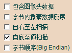
6. Do not check any of the five options as shown in the image below.

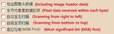
Note: 4.2inch e-ink display needs to check the fourth item
7.Color Inversion: Check to display the original colors, uncheck for color inversion.
8.Click "Save" to save the converted array to a file with the extension ".c".
9. Finally, replace the corresponding array in your program code with the array from the ".c" file.

Red, Black and White Image Creation and Modeling Instructions
Image Creation
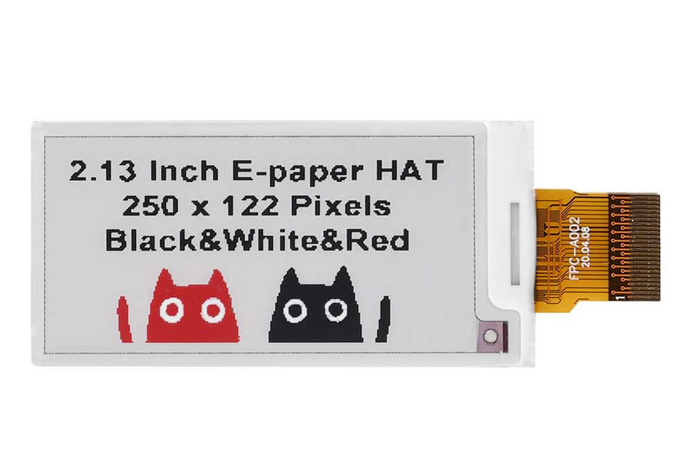
Use Photoshop (PS) or other software capable of creating layers to produce two images, one black and white and one red and white, with resolutions corresponding to the e-ink display model you are using (for example, if using a 2.13inch red black and white e-ink display, you need to create two images with a resolution of 250 x 122 pixels(create black and white and red and white layers to save the images separately)). For the resolutions of compatible e-ink display sizes, please refer to the compatible e-ink display model table above. Save the images as BMP or JPG files (BMP format is recommended).
Modeling
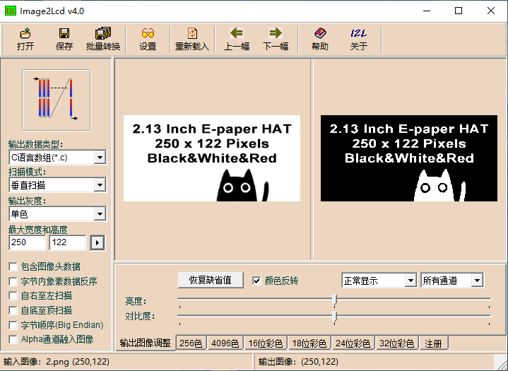
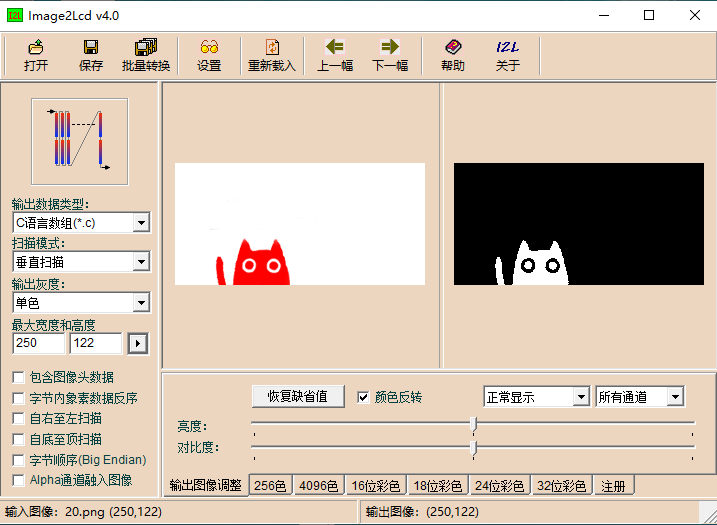
Bitmap creation can be done using the "image2lcd" software, which is provided in the package. The red, black, and white electronic paper needs to be molded twice, and the black and white and red and white images need to be molded separately. Taking the example of achieving the effect shown in Figure 2-4, the parameter settings interface for bitmap creation is shown in Figure 2-5, Figure 2-6:
1. Open the image that needs to be modeled.
2. Output data type: Select "C Language Array (*.c)".
3. Scanning method: Choose "Vertical scanning".
4. Output grayscale: Select "Monochrome".
5. Maximum Width and Height: Fill in the resolution based on the E-Ink screen model you are using (for example, if you are using a 2.13inch e-ink display, fill in "250""122" for both width and height, for the resolutions of compatible e-ink display sizes, please refer to the compatible e-ink display model table above). After making the selection, click the arrow to confirm.
6. Do not check any of the five options as shown in the image below.
7. Color Inversion: Check to display the original colors, uncheck for color inversion.
8. Click "Save" to save the converted array to a file with the extension ".c".
9. Finally, replace the corresponding array in your program code with the array from the ".c" file.
Resources
Example Programs
Data Sheet