Product Overview
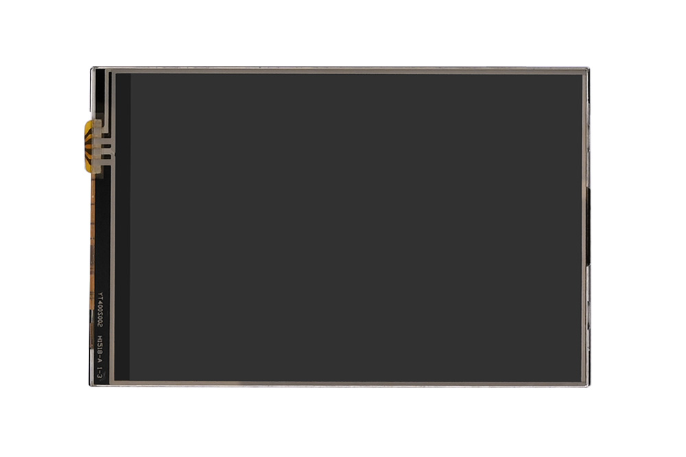
This product is a 4-inch resistive touch screen display designed with a high-performance and user-friendly interface based on the Arduino standard. It operates with just a single circuit board, simplifying hardware connections and the installation process. Combining resistive touch screen technology with a high-resolution 4-inch color display, it offers an intuitive user interface and rich display capabilities. This makes it an ideal choice for Arduino developers and electronics enthusiasts. We provide example codes for both the Arduino UNO and NUCLEO-F103RB versions.
Product dimensions
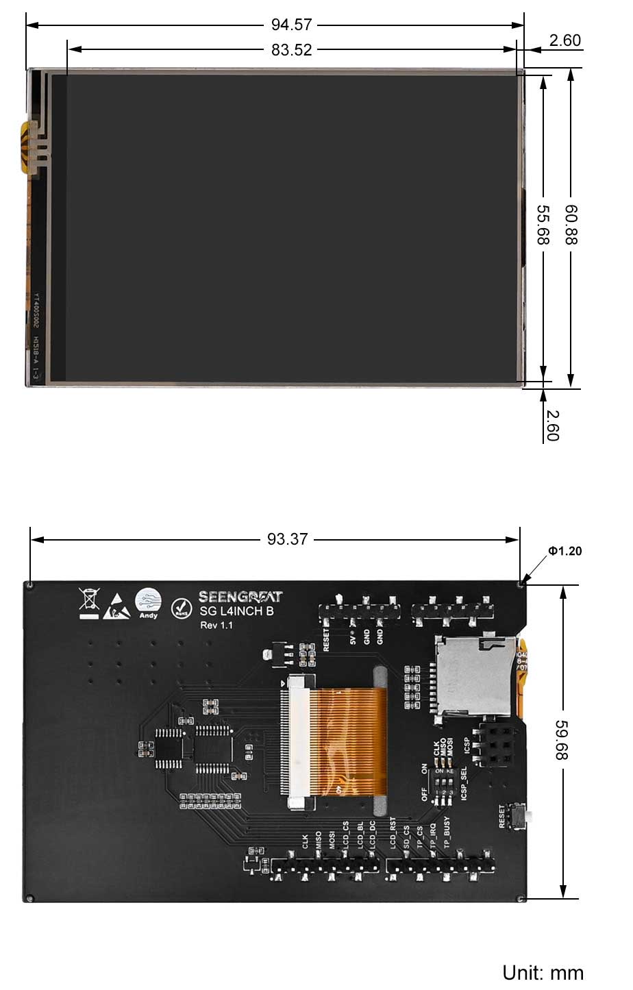
Note: Manual measurement may have an error of no more than 1mm.
Resource Profile
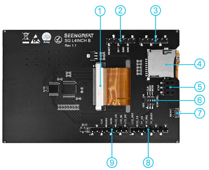
① Screen ribbon cable connector
② Power pin header
③ Analog pin header
④ SD card slot
⑤ ICSP Female Header
⑥ ICSP interface selection DIP switch
⑦ Reset button
⑧&⑨ Digital pin headers
Product Parameters
| Model | SG-L4INCH-B |
| Driver Chip | LCD control chip ST7796S, touch panel control chip XPT2046 |
| Type | TFT |
| Communication Interface | SPI |
| Display Color | RGB ,65K colors |
| Resolution | 480x320 (Pixel) |
| I/O Voltage | 3.3V/5V |
| Dimensions | 94.57mm(Length)×60.88mm(width) |
Use
Use of Arduino UNO
Hardware Interface Configuration Description
| Label | Arduino UNO | Description |
|---|---|---|
| 5V | 5V | 5V Power Input |
| GND | GND | Power Ground |
| CLK | D13 | SPI Clock |
| MISO | D12 | SPI Master Input, Slave Output |
| MOSI | D11 | SPI Master Output, Slave Input |
| LCD_CS | D10 | LCD Chip Select |
| LCD_BL | D9 | LCD Backlight |
| LCD_DC | D8 | LCD Data/Command Selection |
| LCD_RST | D7 | LCD Reset |
| SD_CS | D6 | Micro SD Card Chip Select |
| TP_CS | D5 | Touch Panel Chip Select |
| TP_IRQ | D4 | Touch Panel Interrupt |
| TP_BUSY | D3 | Touch Screen Busy Signal |
Due to the fact that this sample program was validated on the Arduino UNO R3 board, and the SRAM capacity of the board is only 2KB. Therefore, the example program is divided into two project files: image display and touch.
Example Program Usage for Image Display
1. Insert the module correctly into the Arduino UNO development board.
2. Prepare an SD card, which should first be formatted as FAT. Copy the image files from the PIC folder to the SD card, and then insert the SD card into the slot (as shown in the fourth item of Figure 1-4).
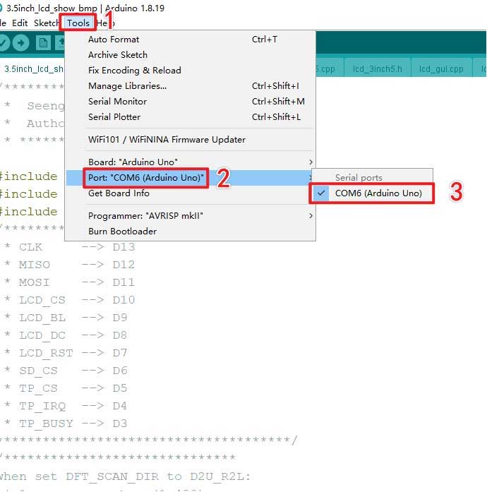
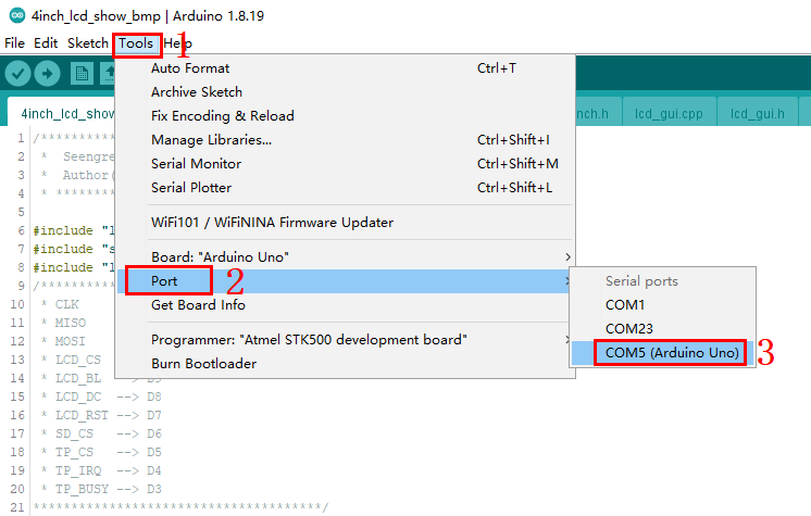
3. Open the image display example program "4inch.lcd-show-bmp. ino" and select the development board model and port number, as shown in the following figure:
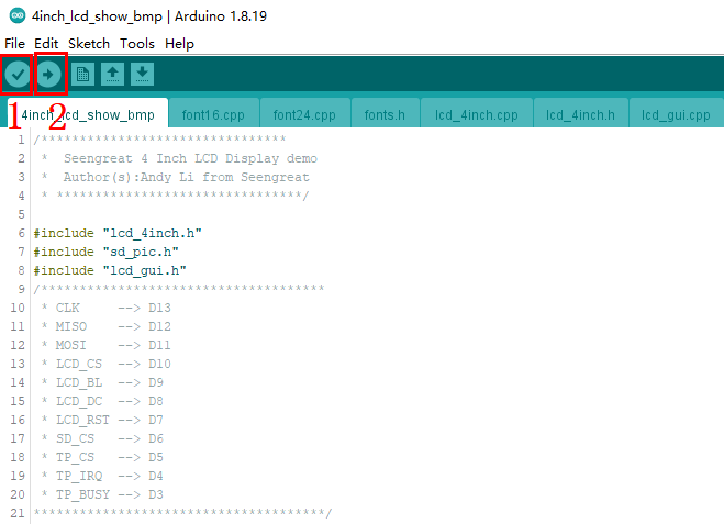
4. After completing the above steps, click on the "Compile" symbol in the upper left corner. If there are no issues with the compilation, click on the "Upload" symbol next to it to upload the sample program to the development board, as shown in the following figure:
5. After successful upload, there will be a custom startup screen on the screen, which will then display the images from the SD card in sequence.
6. If you want the screen to display other images, you can store the images on an SD card. The image format should be BMP, with a bit depth of 24 and a resolution of 480 (width) x 320 (height). In addition, modify the content of the "char file_name [4] [20]" array in line 11 of the sd_pic.cpp file in the image display example program, that is, change its content to the name of the image to be displayed.
Usage of Touch Function Example Program
1. Open the touch function example program "4inch.lcd_touch.ino", select the development board model and port number, and then compile and upload it to the development board.
2. After successful upload, there will be a custom startup screen on the screen, which will first display lines, rectangles, block fillers, circles, characters, etc., and then enter the touch function display interface, as shown in the following figure:
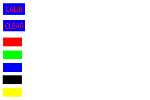
3. In the touch function display interface, the "CALIB" button is used for screen calibration function. The screen calibration parameters have been filled in the TP_Snit() function. Users can also update the values of tp_dev.xfac and tp_dev.yfac based on their calibration results. After successful calibration, the message "Touch screen calibration normal" will appear on the screen. If calibration fails, the calibration will restart. If the user does not perform the calibration operation within 10 seconds, the calibration process will automatically exit.
4. The "CLEAR" button is used to clear the content of the screen drawing board, which can clear all the content drawn by the user on the screen drawing board. The red, green, blue, black, and yellow block buttons are used for pen colors. The default pen color is black. If users want to switch colors, they can first press the corresponding color block button and then draw.
Use of UNCLEO-F103RB Example Program
Hardware Interface Configuration Description
The module can be directly interfaced with the UNCLEO-F103RB motherboard. The wiring definitions are as shown in the table below:
| Label | UNCLEO-F103RB | Description |
|---|---|---|
| 5V | 5V | 5V Power Input |
| GND | GND | Power Ground |
| CLK | PA5 | SPI Clock |
| MISO | PA6 | SPI Master Input, Slave Output |
| MOSI | PA7 | SPI Master Output, Slave Input |
| LCD_CS | PB6 | LCD Chip Select |
| LCD_BL | PC7 | LCD Backlight |
| LCD_DC | PA9 | LCD Data/Command Selection |
| LCD_RST | PA8 | LCD Reset |
| SD_CS | PB10 | Micro SD Card Chip Select |
| TP_CS | PB4 | Touch Panel Chip Select |
| TP_IRQ | PB5 | Touch Panel Interrupt |
| TP_BUSY | PB3 | Touch Screen Busy Signal |
As the UNCLEO-F103RB motherboard does not have an ICSP interface, all positions of the ICSP interface selection switch (as seen ⑥ in Figure 1-4) need to be toggled to the ON state.
Example Program Usage
This sample program is developed based on the HAL library and has the same driver program and program framework as the Arduino UNO platform; Due to the sufficient SRAM and flash memory capacity of STM32F103RB, all functions are integrated into one project.
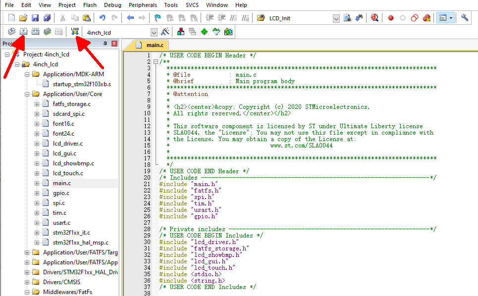
1. Open the project file located at STM32 \ 4 inches lcd \ MDK-ARM \ 4 inches lcd. uvprojx, click the "Build" button, and wait for the compilation to complete.
2. Then click the "Download" button and wait for the download to end. As shown in the following figure:
Resources
Product