Product Overview
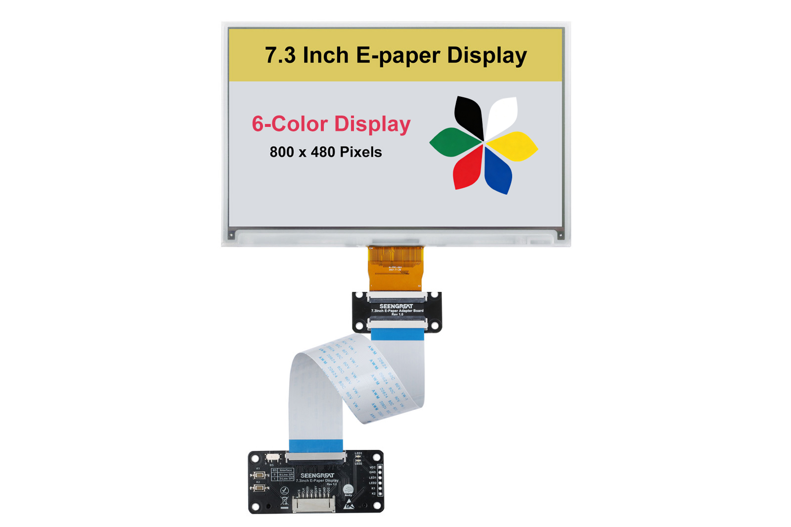
This product is a 7.3-inch seven-color(E6 is six-color) E-Ink display expansion module with a resolution of 800 x 480 pixels. It supports seven colors: black, white, red, green, blue, yellow, and orange(only for seven-color model). It is suitable for display applications such as electronic labels, photo albums, e-readers, and industrial instruments.
The product is compatible with Raspberry Pi series boards, Arduino, STM32, ESP32(only for E6 model) and similar platforms. We provide example codes for Raspberry Pi in both C and Python, as well as for Arduino and STM32 platforms. These examples support drawing points, lines, rectangles, circles, displaying English and numeric characters, and showing color images.
Product Features
- 800 x 480 pixels resolution
- Displays in seven colors: black, white, red, green, blue, yellow, and orange(E6 model is six colors:black, white, red, green, blue, yellow)
- Very low power consumption, only consumes power during refresh
- Provides open-source example programs for Raspberry Pi, Arduino, ESP32(only for E6 model) and STM32 development boards
Product Specifications
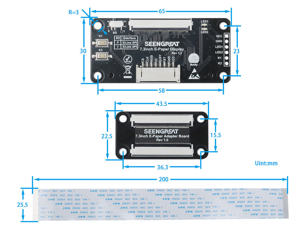
| Module Dimensions | 65.26mm (Length) x 30.61mm (Width) |
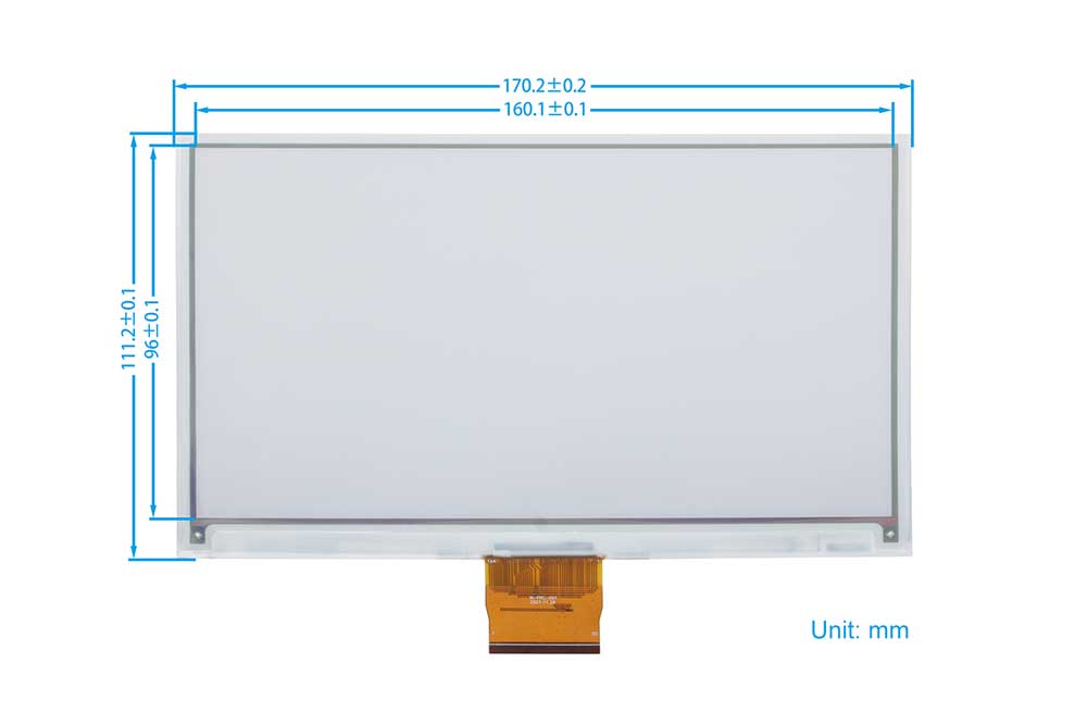
| E-Ink Display Dimensions | 170.2mm (Length) x 111.2mm (Width) x 1.0mm (Height) |
| Weight | Screen 34.3g + Driver Board 16.7g |
| Display Area | 160mm x 96mm |
| Pixels | 800 x 480 |
| Display Colors | Seven colors :black, white, red, green, blue, yellow and orange(E6 is Six colors:black, white, red, green, blue, yellow) |
| Voltage Translator | TXS0108EPWR |
| Signal Interface | SPI |
| Power Supply Voltage | 5V/3.3V |
| Full Refresh Time | 35s |
| Power Consumption | 50mW |
| Standby Power Consumption | 0.003mW |
Usage
All demo codes provided by this product are based on the 4-wire SPI mode, so the BS selection switch on the back of the board is set to "0" by default.
Resource Introduction
The resource introduction is as shown in the following figure:
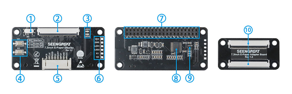
1. SPI Line Selection Switch
2. E-Ink Display Interface or FPC Extension Connector
3. Two User LEDs
4. Two User Buttons
5. Reserved E-Ink Display Control Interface Connector
6. Reserved LED and Button Expansion Pins
7. Raspberry Pi 40-PIN GPIO Header
8. Voltage Translator TXS0108EPWR
9. Power Chip
10. E-Ink Display Interface Adapter Board
Raspberry Pi Example Usage
For the Raspberry Pi 5, when using the lgpio library with its C language version, we need to add the content "dtoverlay=spi1-2cs" at the end of the /boot/firmware/config.txt file and then restart the device. If using the Python language version, the content "dtoverlay=spi1-2cs" should be commented out.
Hardware Interface Configuration
For the Raspberry Pi mainboard, the example programs under the Bullseye system use pin definitions encoded with wiringPi, while those under the Bookworm system use BCM encoding. The pin definitions for connecting to the Raspberry Pi mainboard are as shown in the table below:
| E-Ink Display Interface | Pin Function | BCM Number | wiringPi Number |
|---|---|---|---|
| VCC | 3.3V | 3.3V | 3.3V |
| GND | GND | GND | GND |
| RST | P0 | 17 | 0 |
| BUSY | P5 | 24 | 5 |
| D/C | P6 | 25 | 6 |
| MOSI | P_MOSI | 10 | 12 |
| CLK | P_SCK | 11 | 14 |
| CS | P_CE0 | 8 | 10 |
| LED1 | P7 | 4 | 7 |
| LED2 | P1 | 18 | 1 |
| K1 | P2 | 27 | 2 |
| K2 | P6 | 22 | 6 |
WiringPi Library Installation
Firstly, use the "gpio -v" command in the terminal to check if the WiringPi library is installed. If version 2.52 information appears, the installation is successful. You can skip this section; otherwise, follow the steps below to install it:
sudo apt-get install wiringpiFor Raspberry Pi systems after May 2019 (excluding earlier systems), you may need to upgrade:
wget https://project-downloads.drogon.net/wiringpi-latest.deb
For Raspberry Pi 4B upgrades, if your download fails or is very slow, you can download it from the following link and then copy it to your Raspberry Pi mainboard.
#https://github.com/seengreat/wiringpi-library
sudo dpkg -i wiringpi-latest.deb
gpio -v #
# If version 2.52 appears, the installation is successful.
# For the Bullseye branch system, use the following command:
git clone https://github.com/WiringPi/WiringPi
cd WiringPi
. /build
gpio-v
# Running gpio -v should produce version 2.70. If it doesn't display, there is an installation error.
If you encounter an error message "ImportError: No module named 'wiringpi'" while running the Python version of the example program, please execute the following command:
# For Python 2.x versions
pip install wiringpi#For Python 3.x versions
pip3 install wiringpiNote: If the installation fails, you can try the following compile and install steps:
git clone --recursive https://github.com/WiringPi/WiringPi-Python.gitNote: The --recursive option can automatically fetch submodules; otherwise, they need to be manually downloaded.
Navigate to the downloaded WiringPi-Python folder and execute the following commands to compile and install:
#For Python 2.x versions
sudo python setup.py install#For Python 3.x versions
sudo python3 setup.py installIf you encounter the following error:
Error: Building this module requires either that swig is installed
(e.g.,'sudo apt install swig') or that wiring_wrap.c from the
source distribution (on pypi) is available
At this point, enter the command "sudo apt install swig" to install swig. Then, compile and install "sudo python3 setup.py install". If you see a message similar to the following, the installation is successful.
ges
Adding wiringpi 2.60.0 to easy-install.pth file

Installed /usr/local/lib/python3.7/dist-packages/wiringpi-2.60.0-py3.7-linux-armv7
Processing dependencies for wiringpi==2.60.0
Finished processing dependencies for wiring==2.60
lgpio Library Installation
For the Bookworm system, the example programs use the lgpio library. Here are the installation commands for this library:
wget https://github.com/joan2937/lg/archive/master.zip
unzip master.zip
cd lg-master
make
sudo make install
Enable SPI Interface
sudo raspi-configTo enable the SPI interface:
Interfacing Options -> SPI -> YesTo view enabled SPI devices:
ls /dev/spi* #At this point, it will print out "/dev/spidev0.0" and "/dev/spidev0.1".
Python Library Installation
The example programs use the Python 3 environment. To run Python example programs, you need to install the pil, numpy, and spidev libraries. Use the following commands to install them sequentially:
sudo apt-get install python3-pil
sudo apt-get install python3-numpy
sudo apt-get install python3-pip
sudo pip3 install spidev
Installation of the Freeimage Library
To use the Freeimage library in the C example programs, you need to install the Freeimage library. Here are the commands to install it:
sudo apt-get update
sudo apt-get install libfreeimage-dev
C Version Example Programs
Navigate to the project's C directory.
sudo make clean
sudo make
sudo ./main
After entering the above commands, you can observe the E-Ink display status.
Python Version Example Programs
Navigate to the project's Python directory:
cd test
python3 epd_demo.py
After entering these commands, you can observe the E-Ink display status.
Arduino Example Usage
Hardware Interface Configuration
| E-Ink Display Interface | Arduino UNO Interface |
|---|---|
| VCC | 5V |
| GND | GND |
| RST | D9 |
| BUSY | D8 |
| D/C | D10 |
| MOSI | D13 |
| CLK | D12 |
| CS | D11 |
Use the Arduino IDE software to open the project example files, click on "Verify" to ensure there are no errors, then upload them to the module. Observe the E-Ink display for correct functionality.
STM32 Example Usage
Hardware Interface Configuration
| E-Ink Display Interface | STM32 Interface |
|---|---|
| VCC | 3.3V |
| GND | GND |
| RST | PA11 |
| BUSY | PA12 |
| D/C | PA8 |
| MOSI | PB15 |
| CLK | PB13 |
| CS | PB12 |
Example Usage
Use the Keil uVision5 software to open the project example files, compile without errors, then download them to the module. Observe the E-Ink display for correct functionality.
ESP32 Example Usage
Hardware Interface Configuration
Considering the memory constraints, this sample code is based on the ESP32-S3 module. The following table shows the definitions of the connected pins:
| E-Ink Display Interface | ESP32 Interface |
|---|---|
| VCC | 3.3V |
| GND | GND |
| RST | IO46 |
| BUSY | IO9 |
| D/C | IO3 |
| MOSI | IO11 |
| CLK | IO12 |
| CS | IO21 |
Example Usage
Use the Arduino IDE software to open the project example files, click on "Verify" to ensure there are no errors, then upload them to the module. Observe the E-Ink display for correct functionality.
Changing Displayed Images
Raspberrry Pi
C Version:
1. Place the image you want to display in the pic folder path under the C version example directory (...\c\pic\). Supported formats include BMP, JPG, PNG, GIF, TIF, among others.
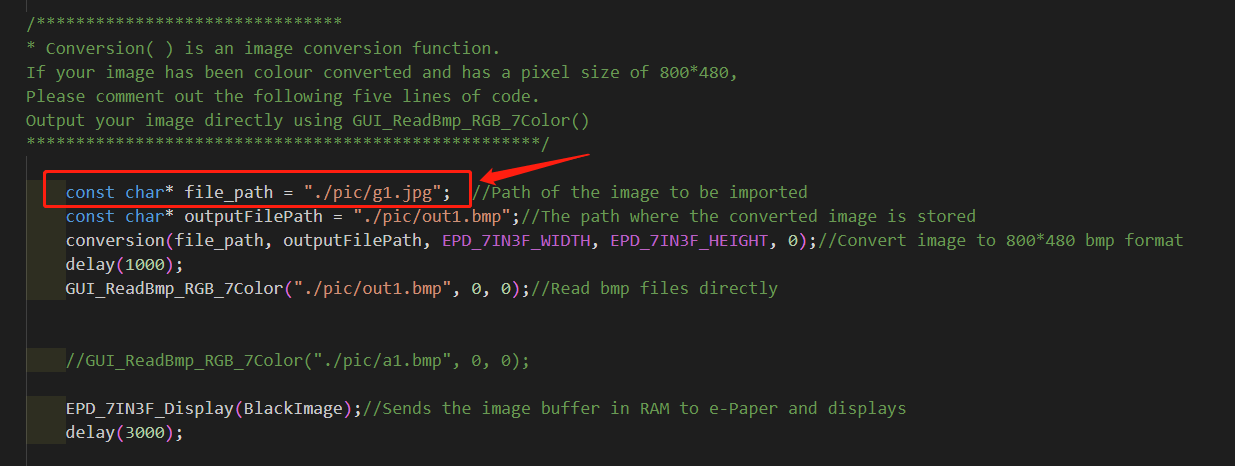
2. Open the main.c program, locate the input image file path in the main function, change it to your image file name, and then save it. See Figure 2-2 below.
3. Re-compile and run the program (refer to section 2.2.6 for details).
Python Version:
1. Place the image you want to display in the pic folder path under the Python version example directory (...\python\pic\). Supported formats include BMP, JPG, PNG, GIF, TIF, among others.
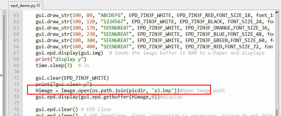
2. Open the epd_demo.py file under the test directory, locate the input image path, change it to your image file name, and then save it. See Figure 2-3 below.
3 Use the command sudo python3 epd_demo.py to run the program and observe the E-Ink display.
Arduino
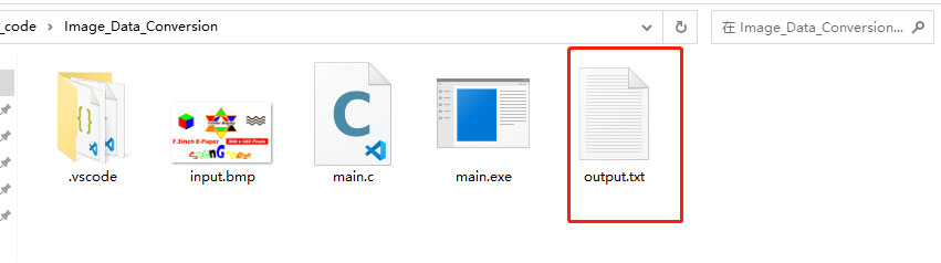
1. Prepare the image you want to display. Follow the steps in section 2.6 to process the image and obtain an image array file output.txt, as shown by the red box in Figure below.
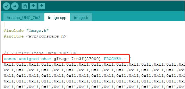
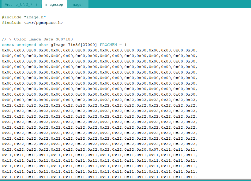
2. Open the output.txt file, copy all its contents, replace the image data in the image.cpp file with it, and click save. As shown in Figure 2-5 below.
3 Re-compile and upload the program to the target board.
STM32
1. Prepare the image you want to display. Follow the steps in section 2.6 to process the image and obtain an image array file output.txt, as shown by the red box in Figure 2-4.
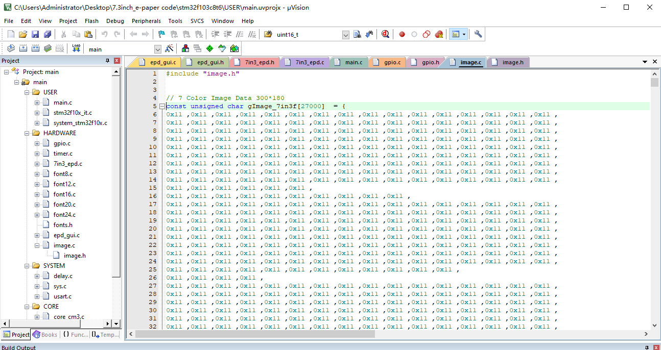
2. Open the output.txt file, copy all its contents, replace the image data in the image.c file with it, and click save. As shown in Figure 2-6 below.
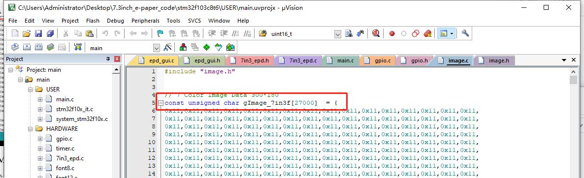
3 Re-compile and upload the example program.
Image Creation and Modeling Instructions
This section only applies to Arduino and STM32 platforms. It is not necessary for Raspberry Pi platforms to follow these steps for displaying images. The images displayed must be smaller than the screen's maximum size of 800 x 480 pixels.
Image Creation
This step involves converting the desired color image into a seven-color(E6 is six-color) image and saving it in BMP format.
Image creation requires Adobe Photoshop software and the built-in Paint tool in Windows. Adobe Photoshop needs to be downloaded and installed by the user.
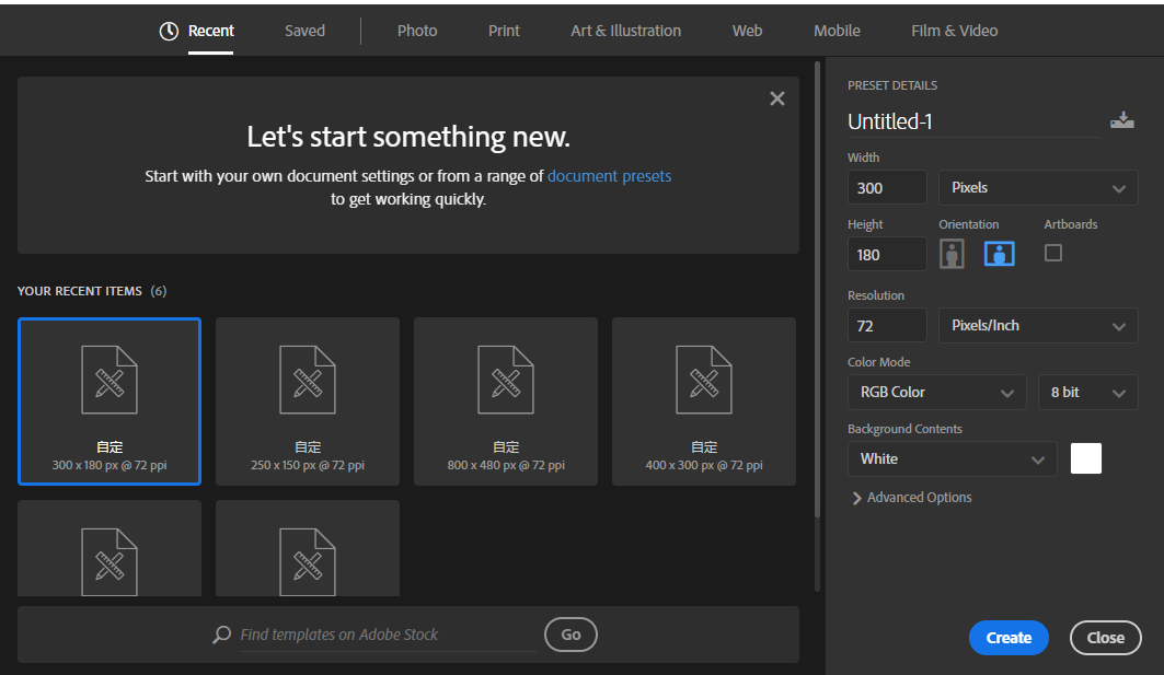
1. Open Adobe Photoshop, create a new blank project, set the width and height according to the desired resolution for display, and use RGB color mode. For example, if you want the image size to be 300*180 pixels, set the width to 300 pixels, height to 180 pixels, and choose a white background. As shown in Figure 2-7 below.
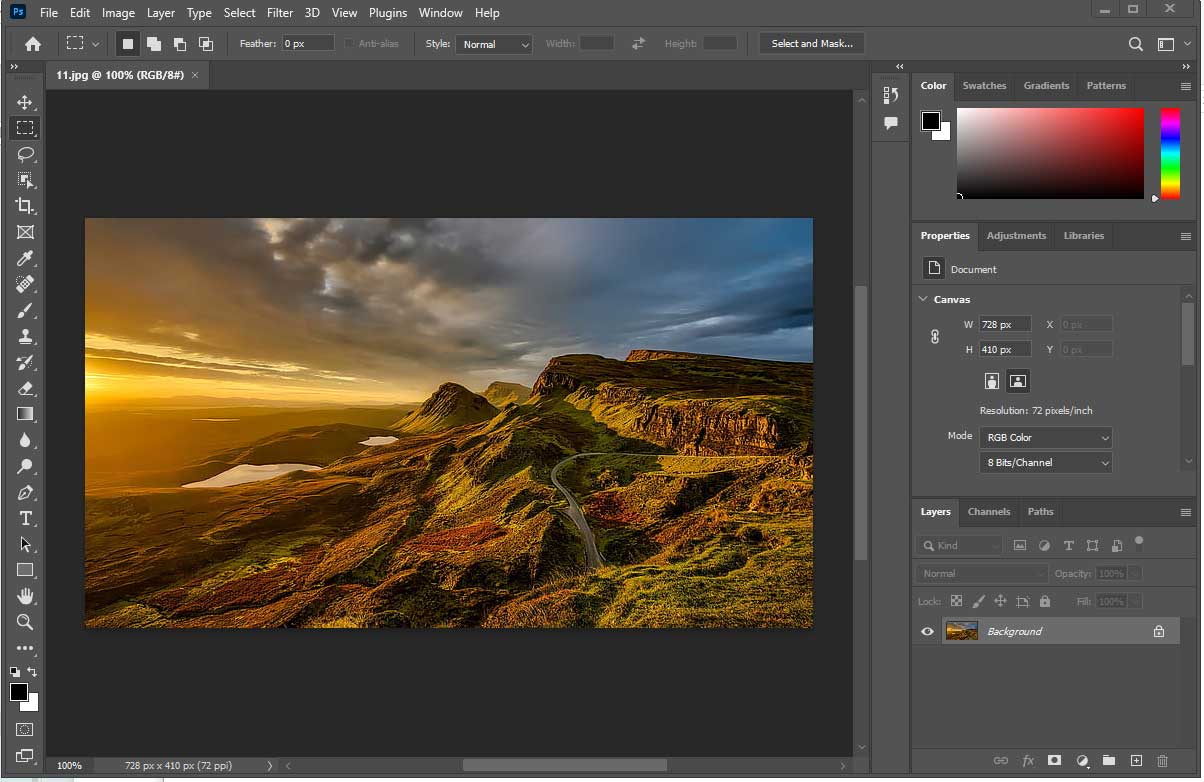
2. Click on File -> Open... to import the image into the newly created blank image. Adjust the size and position accordingly. You can also modify the image parameters (similar to the usual image editing process in Photoshop), as shown in Figure 2-8.
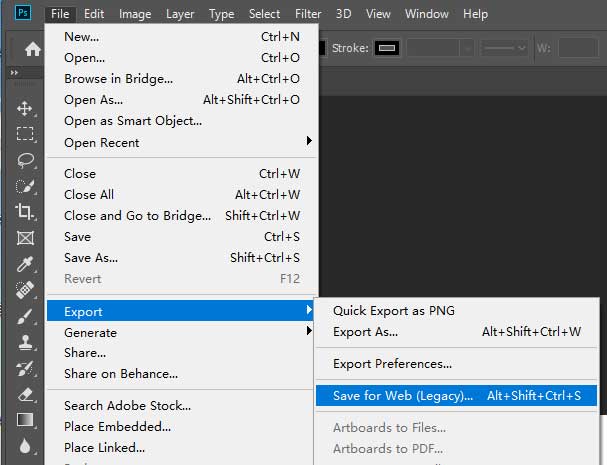
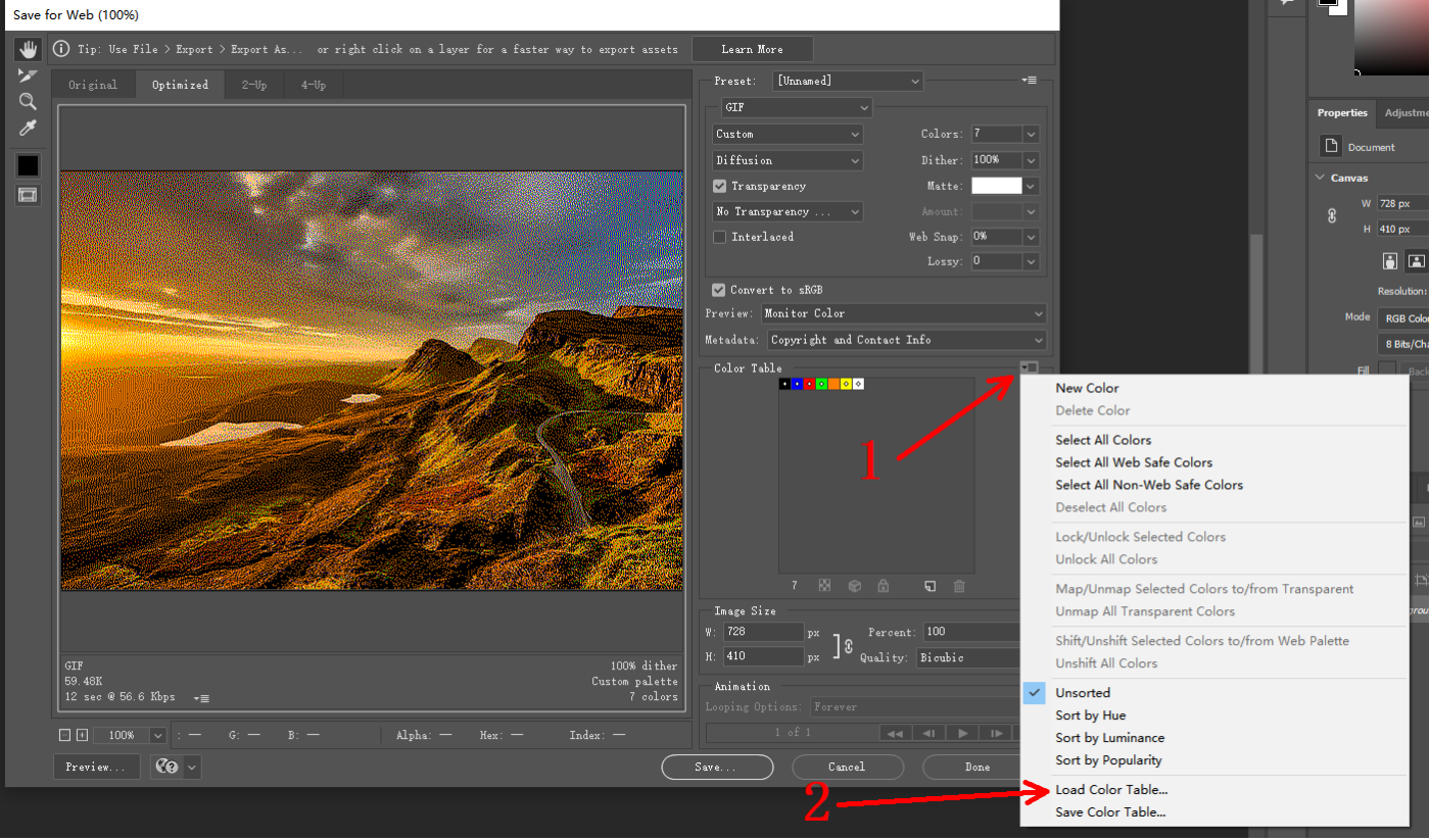
3. Select File -> Export -> Save for Web (Legacy)..., export the file, as shown in Figure 2-9:
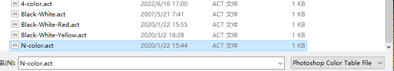
4. As shown by the red arrows in Figure 2-10 below, click on positions 1 and 2 sequentially, select "Load Color Table," and load the color table file named N-color.act(E6 model is 6-color.act). The color table file is stored in the user's compressed package, as illustrated in Figure 2-11.
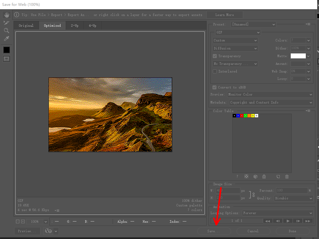
5. After loading the color table, as shown in Figure 2-12, click on "Save..." indicated by the red arrow to save it as a GIF file.
6. Using the built-in Paint tool in Windows, convert the GIF file to 24-bit BMP format to complete the process.
Modeling
The above steps have already transformed the ordinary image into a seven-color image. If you intend to use it on Arduino and STM32, further modeling processing is required.
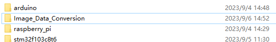
We have prepared a sample program for modeling in the folder named "Image_Data_Conversion" in the compressed package, as shown in Figure below.
1. Using Visual Studio Code (GCC compiler and its environment setup required) open the "Image_Data_Conversion" folder. In the main function, modify the path to your imported image, which should be the BMP format file processed in the previous step.
Special Note: Directly copied file paths from Windows cannot be used directly in the example code. You need to replace '' with '/' or '\' in the copied path, as shown in Figure below.
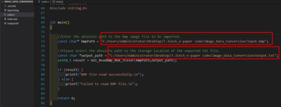
2. After modifying the path, the program will store the data of the BMP image as an array and output it in TXT format. Please select the complete path for exporting the TXT file. It is recommended to store the output TXT file in the same folder as the input BMP image.
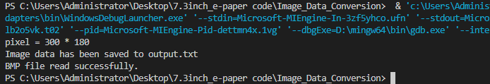
3. Once you have updated the path, run the program. The display should resemble Figure below.
4. Open the exported TXT file and replace the data inside with the corresponding arrays in the STM32,ESP32 and Arduino demo codes. Finally, download the demo codes to the development board to display the new image. The image data in the demo codes is stored in the respective files: image.c (for STM32 platform) and image.cpp (for Arduino and ESP32 platform), as shown in Figures below.
The formula for calculating the length of the image data storage array is: Len = width * height / 2. This means one byte represents two pixels. Due to varying flash sizes on different platforms, you may encounter errors during compilation indicating insufficient memory if the array size is too large. Users should adjust the image size based on practical considerations. Different image sizes require modifications to the array size and the values of the parameters image_width and image_height in the EPD_7IN3F_Display function, where image_width represents the width of the image and image_height represents the height.
Resources
demo codes for six-color model(E6)
demo codes for seven-color model
Datasheet
Related Links
Python's image library:
If users need to implement additional functionality, they can learn more on the official website: https://pillow.readthedocs.io/en/latest/handbook/index.html.
FreeImage library download link:
https://sourceforge.net/projects/freeimage/