Product Overview
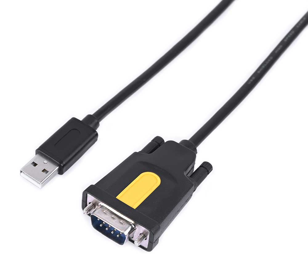
This product features a black PVC cable jacket, aluminum connectors, and DB9 interface with anti-slip fixing screws. It has a wide range of applications, suitable for devices such as scanners, touch screens, and industrial control computers. It is compatible with Windows, Mac OS, and Linux systems. The product comes with built-in CH340/PL2303/FT232 driver chips, making it plug-and-play.
Resource overview is as shown in the following figure:
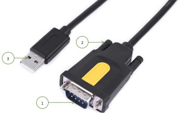
1. RS232 DB9 Male
2. Anti-slip fixing screws
3. USB Type A connector
Product Parameters
| Model | USB-To-RS232 Male-CH340 | USB-To-RS232 Male-PL2303 | USB-To-RS232 Male-FT232 |
|---|---|---|---|
| Driver Chip | CH340C | PL2303GT | FT232RL |
| Baud Rate | 50bps—2Mbps | 75bps—1Mbps | 300bps—1Mbps |
| Driver Support | Windows, Linux, Mac OS | ||
| Host Interface | USB Type A Connector | ||
| Device Interface | USB-To-RS232-Male-Cable: RS232 DB9 Male head | ||
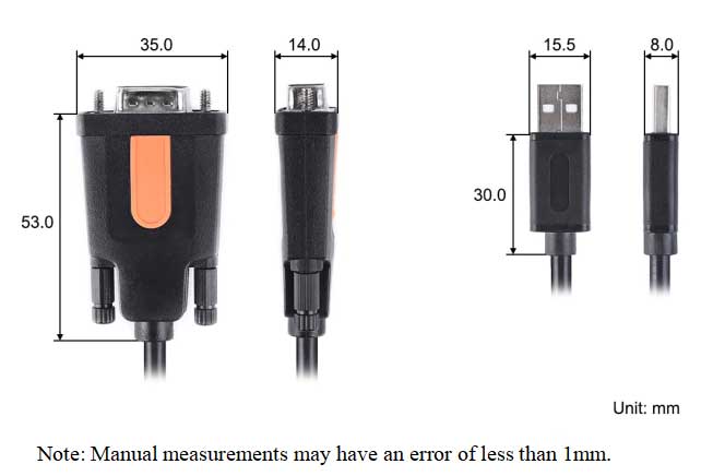
| Dimensions | 1500mm (Length) * 5mm (Width) | ||
| Cable Specifications | Black, PVC Outer Jacket, VW-1 | ||
| Cable Rated Temperature/Voltage | 80℃ / 30V | ||
Usage
Connect the USB Type A connector of the product to the host,and use a serial assistant on the host to send data to devices connected to RS232 DB9 Male. This routine takes raspberry pie as an example,Use the Uartassist.exe serial assistant on your computer to configure the same baud rate as Raspberry Pi minicom,Using a serial assistant to send data to Raspberry Pi, The minicom window on the Raspberry Pi will display the data sent by the computer.
Windows Driver Installation
Download the relevant drivers
| PL2303 | |
| FT232 | Windows64:https://FT232_Driver_win64.rar Windows32:https://FT232_Driver_win32.rar |
| CH340 |
PL2303 Driver Installation Steps:
Open the download driver file, click the PL23XX-M_LogoDriver...file.
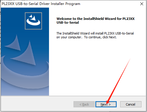
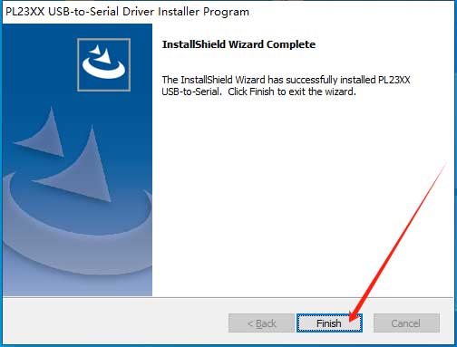
Click to start the installation of the PL2303 driver, click Next, wait for the installation to complete, and click Finish.
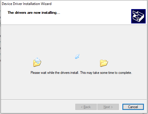
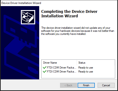
FT232 Driver Installation Steps:
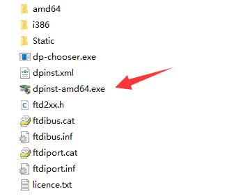
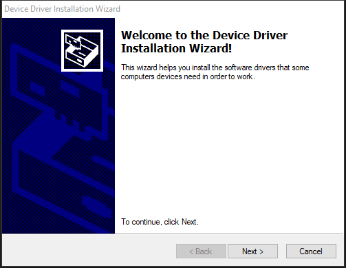
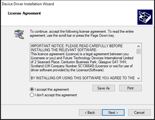
The FT232 driver download link is only for distinguishing between 32-bit and 64-bit systems, but the installation steps remain the same. Below are the steps to install the FT232 driver using a 64-bit system as an example:
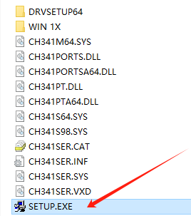
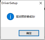
CH340 Driver Installation Steps:
Open the downloaded driver file and double-click the SETUP.EXE file.
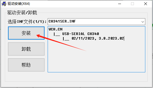
Select install, then wait for the installation to complete.
Device Connection (Using Raspberry Pi as an Example):
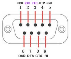
RS232 DB9 Male Connector Pin Definitions
| PIN | Name | Function |
|---|---|---|
| 1 | DCD | Data Carrier Detect |
| 2 | RXD | Receive Data |
| 3 | TXD | Transmit Data |
| 4 | DTR | Data Terminal Ready |
| 5 | GND | Ground |
| 6 | DSR | Data Set Ready |
| 7 | RTS | Request To Send |
| 8 | CTS | Clear To Send |
| 9 | RI | Ring Indicator |
Connection Steps:
1.Check Device Usability
Ensure that the Raspberry Pi is connected to a display, mouse, and keyboard. Due to the voltage level structure, we cannot directly connect the RS232 signal to the Raspberry Pi platform, as it may damage the Raspberry Pi. In this case, an alternative method is needed for connection. One method is to use a USB to RS232 converter to assist in connecting to the Raspberry Pi. This converter can convert the RS232 baud rate to a USB-compatible baud rate and convert the output voltage level to the standard USB logic level of 5V.
| RS232 Serial Cable | raspberry pi | |
| Logic Level | ±3V——±15V | 3.3V |
Note:
When connecting the RS232 serial cable to other devices for communication, consider whether the device's voltage level structure is suitable for the RS232 serial cable.
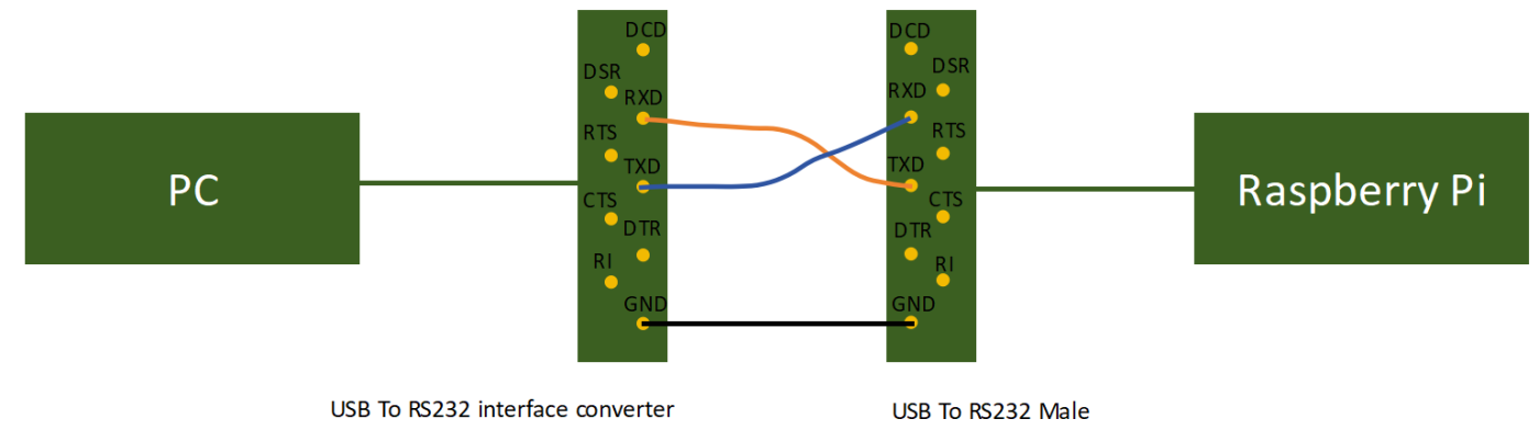
2.Connecting DuPont Wires:
Cross-connect the TXD and RXD pins of the RS232 serial cable to the DB9 port of the USB to RS232 converter, and connect the GND pins to each other.
3.Once the connections are completed, refer to the diagram below:
Testing
Initialization Configuration
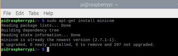
Install the serial assistant on the Raspberry Pi. Open the terminal on the Raspberry Pi and enter the following command:
sudo apt-get install minicomThe result of the installation completion is displayed as shown in the following figure:
Device Recognition (Using FT232 as an Example):
1. Open the terminal on the Raspberry Pi. After connecting the device, run the following command to detect whether the device is recognized. If the content displayed in the red box below appears as shown in the figure, it indicates that the device has been recognized.
Enter the command:
lsusb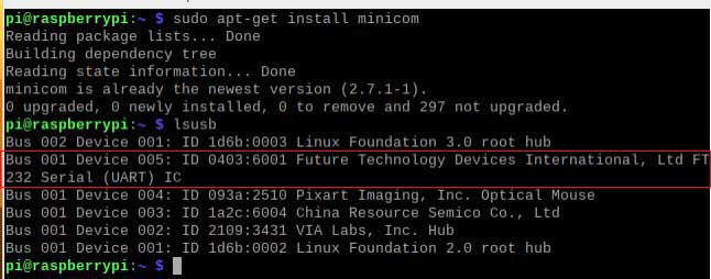
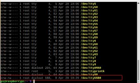
2. Then enter the command to view the recognized serial port number.
ls -l /dev/tty*Because the USB-To-RS232-Male-FT232 belongs to the USB serial converter device, the content highlighted in the red box in the figure is the serial port number we need to recognize.
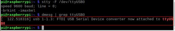
3. Execute the command to view the serial port baud rate.
stty -F /dev/ttyUSB0The terminal displays the following content:

4. Enter the command to view the serial port connection information. You will see the relevant information of the latest connected USB device.
dmesg | grep ttyUSB0After entering the command, the terminal displays the content as shown in Figure below.
Configuring minicom
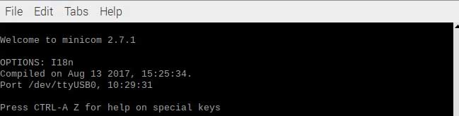
1.Enter the following command in the terminal to open minicom:
minicom -D /dev/ttyUSB0 -b 115200Here, -D /dev/ttyUSB0 points to the serial port number we opened, and -b 115200 configures the baud rate. We can enter Ctrl+A in minicom to view it below. For our baud rate, if -b is not set, the baud rate defaults to 115200. After executing the command, the Raspberry Pi terminal displays as follows:
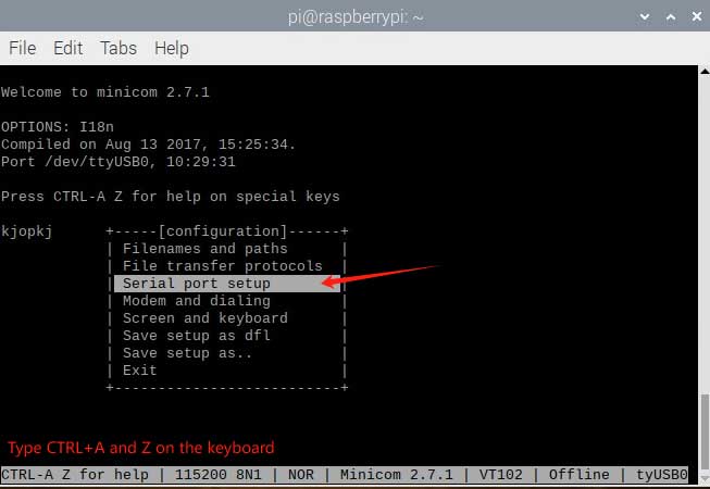
2.Enter the command
sudo minicom -sTo open minicom, then press "Ctrl+A" and then press "Z" to open the serial port menu - select Serial port setup to set up the serial port.
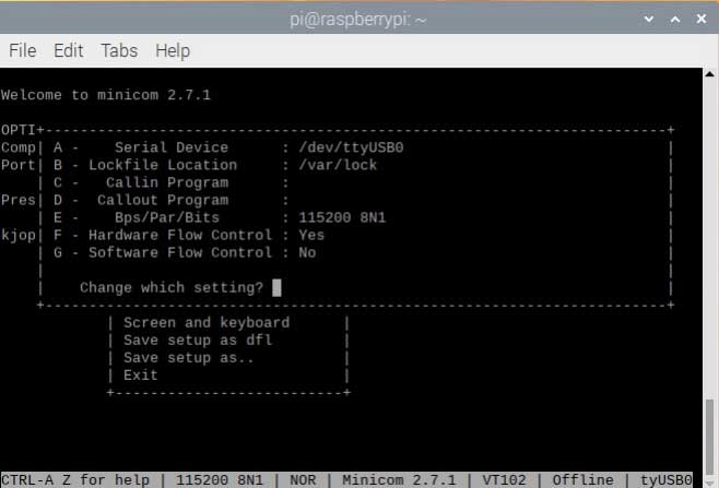
Continue by pressing "O" to open the serial port initialization configuration - follow the window prompts to set the serial port number and baud rate. Set the baud rate to 115200, and the detected serial port number is USB0.
PC Serial Port Initialization
On the PC side, also open the serial assistant (UartAssist.exe) and configure the same baud rate. Choose the appropriate port number. The port number of the serial module may change. You can configure it to the specified COM port through the following steps:
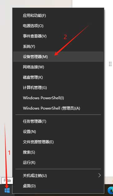
Right-click on the Windows icon/shortcut win+x in the lower left corner of the computer, and then left-click on Device Manager (M).
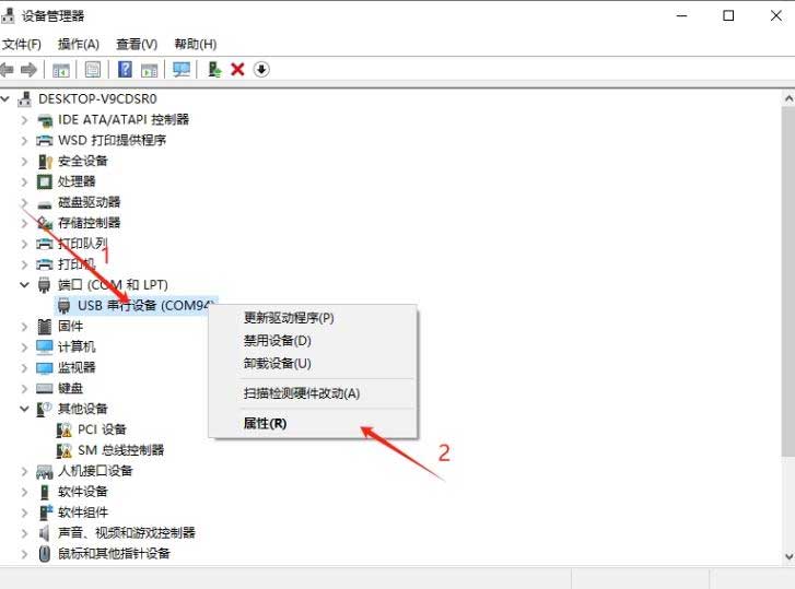
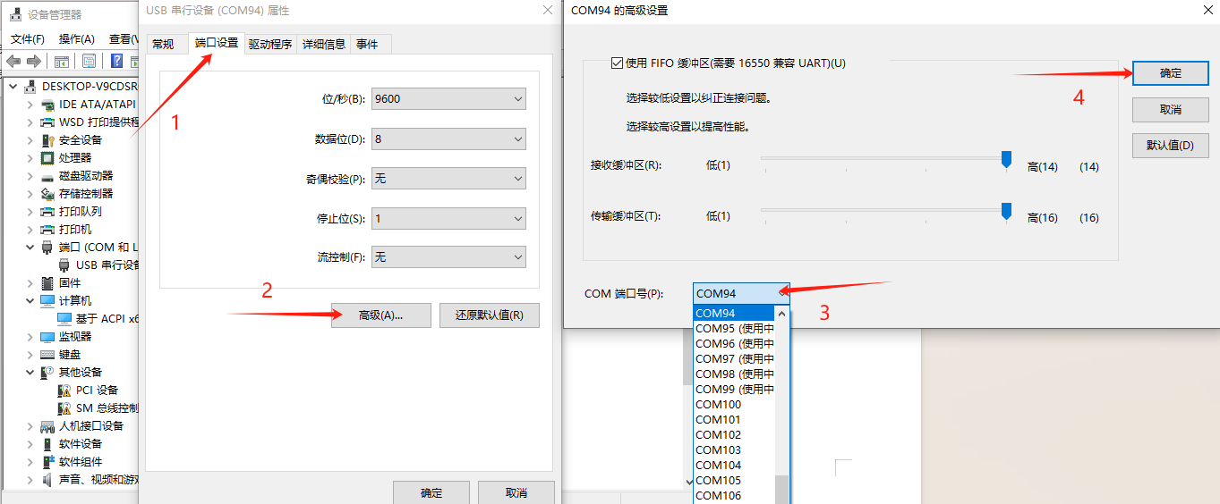
1. Right-click on the corresponding COM port and select Properties:
2. Click "Port Settings" in the window, then click "Advanced", choose the appropriate COM port number in the COM port number (except in use), and finally click OK.
Serial Port Detection
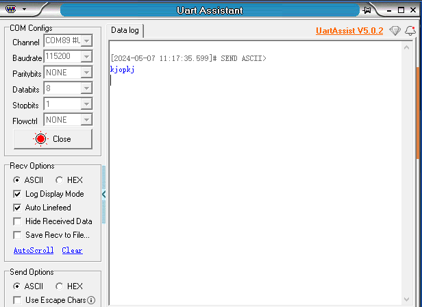
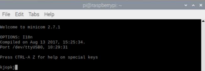
On the PC side, send data for detection. Check whether the minicom on the Raspberry Pi terminal receives the data. Observe whether the serial assistant on the Raspberry Pi displays normal data. The ideal results are as follows:
Note: When using the minicom serial assistant, you may sometimes find that keyboard input does not respond. This may be because the echo function of minicom is not enabled. You can follow these steps to solve this problem: Press the Ctrl + A key combination to enter minicom's command mode; Then press the E key to enable the echo function. If your keyboard input is displayed normally, you do not need to perform these operations.
Resources
Software Downloads
Serial Debugging Assistant Windows
Serial Debugging Assistant Android