This product is a 2.9-inch e-ink display expansion module, suitable for Raspberry Pi series motherboards, Arduino, STM32, and other platforms. We provide example programs in both C and Python for Raspberry Pi, as well as example programs for Arduino and STM32. The example programs support drawing of points, lines, rectangles, and circles, and also enable the display of English alphanumeric characters and images.
Product Parameters
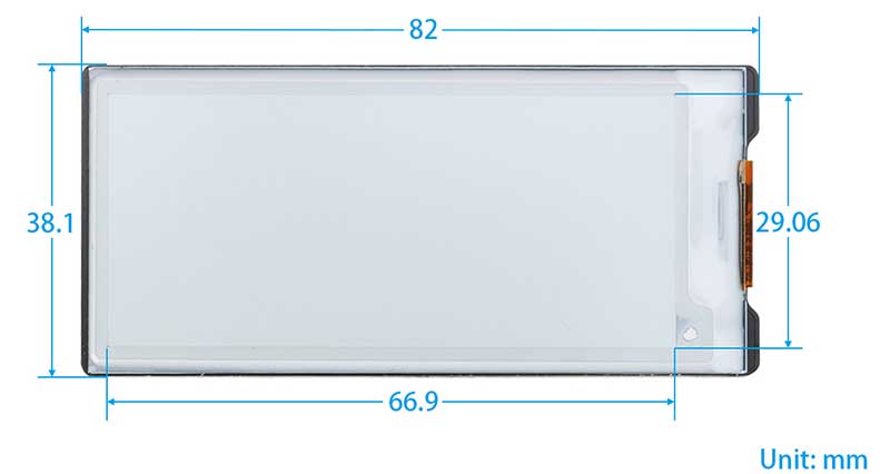
| Dimensions | 82mm (length) x 38mm (width) |
| Weight | 20.6g (with screen) |
| Screw Size | M2.5 |
| Pixels | 296 x 128 |
| Display Color | Monochrome |
| Level Conversion Chip | TXS0108EPWR |
| Communication Interfaces | SPI |
| Power Supply Voltage | 5V/3.3V |
| Display Area | 66.9mm (H) x 29mm (W) |
| Gray Level | 4 |
| Full Refresh Time | 3S |
| Fast Refresh Time | 1.5S |
| Partial Refresh Time | 0.3S |
| Power Consumption | 9mW |
| Standby Power Consumption | 0.003mW |
Pin Definitions
| VCC | 3.3V&5V |
| GND | Ground |
| RST | External Reset Pin (Low-level reset) |
| BUSY | Busy Status Output Pin (High level indicates busy) |
| D/C | Data/Command Control Pin (High level indicates data, low level indicates command) |
| MOSI | SPI Communication MOSI Pin |
| CS | SPI Chip Select Pin (Active low) |
| CLK | SPI Communication SCK Pin |
Usage
Precautions for using the E-Paper:
- Avoid direct sunlight. Electronic paper will display particles under strong light, that is, the charged particles in the microcapsules will dry out under strong light, and then lose their activity and cannot be refreshed. This condition is irreversible. At the same time, moisture-proof and waterproof measures must be taken, and the operation should be strictly in accordance with the temperature and humidity range required by the specification. If the electronic paper is not used for a long time, it needs to be placed upside down, and the screen should be placed with a full white screen.
- After the electronic paper is refreshed, you need to set the sleep mode, or turn off the power after setting the sleep mode. The refresh interval of the SPI serial port electronic paper is at least 180s, especially for large-sized electronic paper, if the interval is too short, afterimages will appear, which will affect the display effect of the electronic paper.
- In order to reduce afterimages, it is recommended to add black and white full-screen refresh display after 5 partial refreshes, and increase the refresh interval.
- If the E-Paper is not refreshed for a long time, it must be powered off or enter the deep sleep mode.
- The EPD Panel / Module is manufactured from fragile materials such as glass and plastic, and may be broken or cracked if dropped. Please handle with care. Do not apply force such as bending or twisting to the EPD panel .
- High temperature, high humidity, sunlight or fluorescent light may degrade the EPD panel's performance. Please do not expose the unprotected EPD panel to high temperature, high humidity, sunlight, or fluorescent for long periods of time. Please store the EPD panel in controllable environment of warehouse and original package.
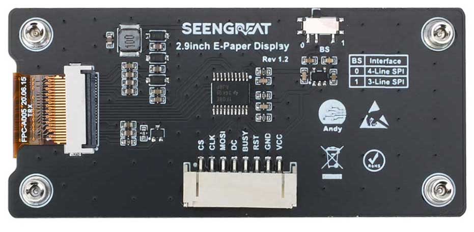
All the demo codes provided by this product are based on the 4-wire SPI mode, so the BS selection switch on the back of the board is set to "0" by default.
Resource Profile
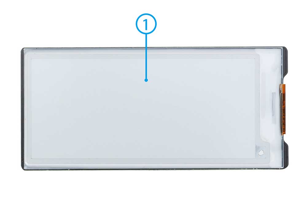
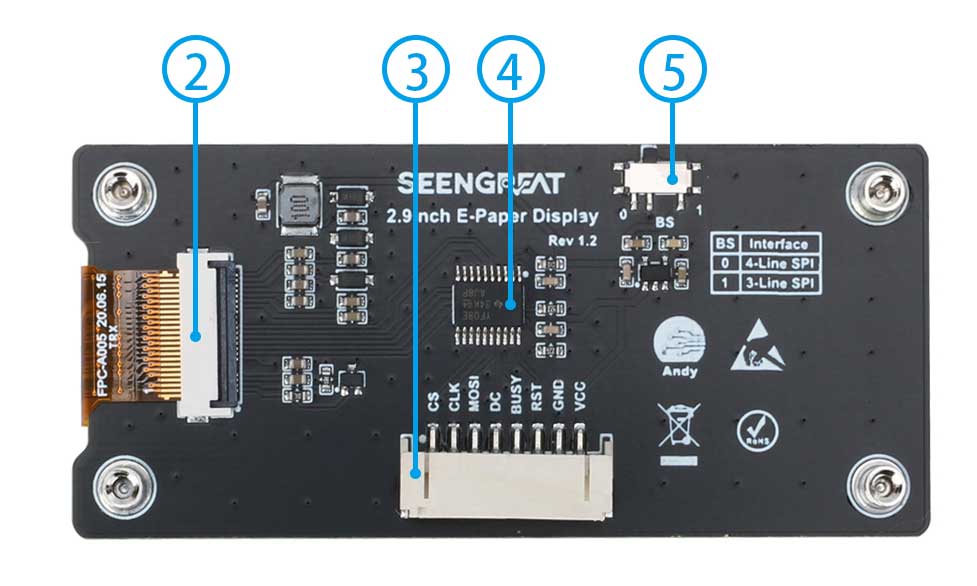
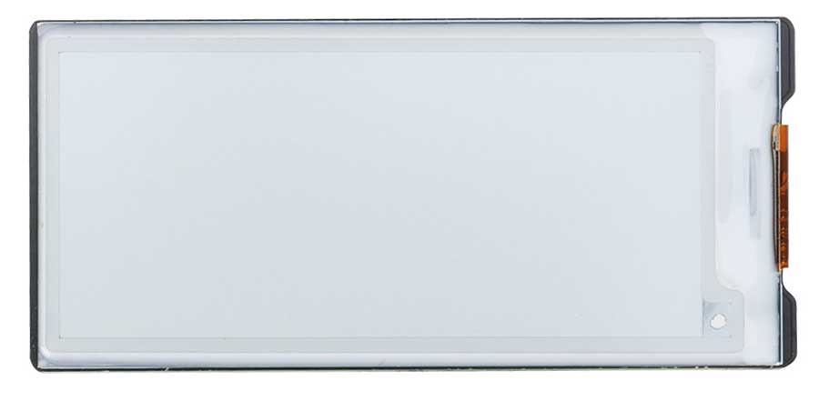
①、2.9-inch e-ink display
②、E-ink display connector
③、SPI control interface connector
④、Level conversion chip TXS0108
⑤、SPI lines selection switch
Raspberry Pi Demo Codes Usage
Since the bookworm system no longer supports the wiringpi library, the example program for this system uses the lgpio library, and for the bullseye system, the wiringpi library version of the example program can be used.
Hardware Interface Configuration Instructions
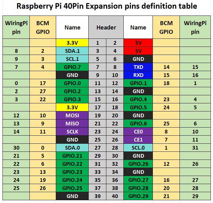
The example program used in the Raspberry Pi motherboard employs pin definitions numbered with wiringPi, and the bookworm system uses the pin definition of the BCM number. The pin definitions for connecting to the Raspberry Pi motherboard are as follows:
| E-Ink Display Interface | wiringPi Encoding | BCM Encoding |
|---|---|---|
| VCC | 3.3V | 3.3V |
| GND | GND | GND |
| RST | P0 | 17 |
| BUSY | P5 | 24 |
| D/C | P6 | 25 |
| MOSI | MOSI/P12 | 10 |
| CLK | SCLK/P14 | 11 |
| CS | CE0/P10 | 8 |
WiringPi library installation
C:
sudo apt-get install wiringpi
wget https://project-downloads.drogon.net/wiringpi-latest.deb # Raspberry Pi 4B version upgrade
sudo dpkg -i wiringpi-latest.deb
gpio -v # If version 2.52 appears, the installation is successful
Python:
pip install wiringpiLgpio library installation
wget https://github.com/joan2937/lg/archive/master.zip
unzip master.zip
cd lg-master
make
sudo make install
Open SPI interface
sudo raspi-configEnable SPI interface:
Interfacing Options -> SPI -> YesView enabled SPI devices:
ls /dev/spi* #At this point, the following will be printed out: "/dev/spidev0.0" and "/dev/spidev0.1".
Installation of python library
The example program uses the Python 3 environment. To run the Python example program, you need to install the PIL, NumPy, and spidev libraries. Enter the following commands to install them one by one:
sudo apt-get install python3-pil
sudo apt-get install python3-numpy
sudo apt-get install python3-pip
sudo pip3 install spidev
C version demo codes
Navigate to the C directory within the example program project files.
sudo make clean
sudo make
sudo ./main
After entering the above command, you can observe the display situation of the e-ink screen.
python Version demo codes
Enter the Python directory in the example program project files.
python3 gui_demo.pyAfter entering the above command, you can observe the display situation of the e-ink screen.
Arduino Example Program Usage
Hardware Interface Configuration Instructions
Table 2-2 is the wiring definition between Arduino Mega and ink screen:
| E-Ink Display Interface | Arduino Interface |
| VCC | 5V |
| GND | GND |
| RST | D9 |
| BUSY | D10 |
| D/C | D8 |
| MOSI | D51 |
| CLK | D52 |
| CS | D53 |
Table 2-2 Pin definition of ink screen and Arduino Mega
Table 2-3 is the wiring definition between Arduino Mega and ink screen:
| E-Ink Display Interface | Arduino Interface |
|---|---|
| VCC | 5V |
| GND | GND |
| RST | D9 |
| BUSY | D8 |
| D/C | D10 |
| MOSI | D13 |
| CLK | D12 |
| CS | D11 |
Table 2-3 Pin definition of ink screen and Arduino UNO
Example Program Usage
Open the project example program file with the Arduino IDE software, click on verify, and after successful verification, upload it to the module. Observe the display situation of the e-ink screen.
STM32 Example Program Usage
Hardware Interface Configuration Instructio
| E-Ink Display Interface | STM32 Interface |
|---|---|
| VCC | 3.3V |
| GND | GND |
| RST | PA11 |
| BUSY | PA12 |
| D/C | PA8 |
| MOSI | PB15 |
| CLK | PB13 |
| CS | PB12 |
Example Program Usage:
Open the example program project file with Keil uVision5 software. After compiling without errors, download it to the module and observe the display situation of the e-ink screen.
ESP32 Example Program Usage
The ESP32 module used in this example program is ESP32-WROOM-32E.
Hardware Interface Configuration Instructions
| E-Ink Display Interface | ESP32 Interface |
|---|---|
| VCC | 3.3V |
| GND | GND |
| RST | IO33 |
| BUSY | IO13 |
| D/C | IO14 |
| MOSI | IO23 |
| CLK | IO18 |
| CS | IO27 |
Example Program Usage:
Open the example program project file with the Arduino IDE software. After compiling without errors, download it to the module, and observe the display situation of the e-ink screen.
Image Creation and Modeling Instructions
Image Creation
Create images that need to be displayed in 296 x 128 resolution as pure black and white images (grayscale is not supported), save them as BMP or JPG files (BMP format is recommended).
Modeling
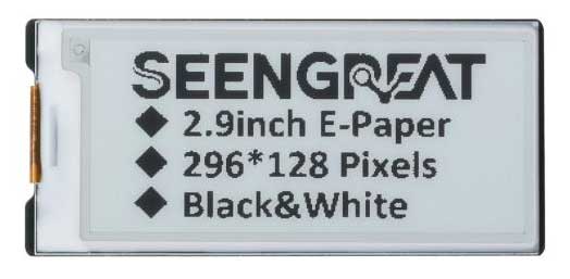
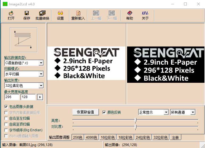
Modeling can be done using the "image2lcd" software provided in the compressed package. Taking the example of achieving the effect in Figure 2-2, the modeling parameter setting interface is shown in Figure 2-3:
1. Open the image that needs to be modeled.
2. Output data type: Select "C Language Array (*.c)".
3. Scanning method: Choose "Vertical scanning".
4. Output grayscale: Select "Monochrome".
5. Maximum width and height: Choose "296" "128". After selection, click the arrow next to it to confirm.
6. Do not check any of the 5 items as shown in the figure below.
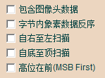
7. Color Inversion: Check to display the original image; uncheck for color inversion.
8. Click "Save" to save the converted array to a file with the extension ".c".
9. Finally, use the array in the ".c" file to replace the corresponding array in the program.
Resources
Example codes for bullseye system
Example codes for bookworm system
Related Links
Python Imaging Library
If users need to implement additional functionality, they can visit the official website to learn more: https://pillow.readthedocs.io/en/latest/handbook/index.html