
Product Overview
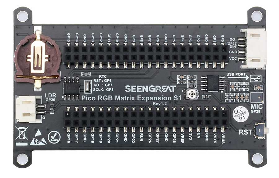
The Pico RGB Matrix Expansion S1 is an expansion board designed specifically for the Raspberry Pi Pico. It features a 10x20 WS2812 RGB LED matrix, DS1302 real-time clock chip, analog silicon microphone audio sampling circuit, light-dependent resistor, and reset button.
Product Parameters
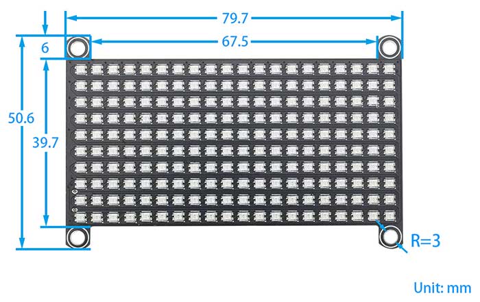
| Dimensions | 79.5mm (length) * 39.8mm (width) * 11mm (height) |
| Weight | 22.5g |
| Mounting Hole Diameter | 3mm |
| Power Supply Voltage | 5V (Powered by Pico) |
| LED Matrix Resolution | 10 * 20 (pixels) |
| RGB LED Color | 24-bit (8 bits per color) |
| RGB LED Communication Method | Single-wire data transmission |
| RGB LED Brightness Levels | 256 levels of brightness |
| RGB LED Data Transfer Rate | 800Kbps/second |
| RTC Chip | DS1302ZM |
| Microphone Pre-amplifier Chip | MCP6022I/SN |
| Microphone Sensitivity | -32db |
| Microphone Frequency Response | 100~10000hz |
| Microphone Output Signal | Analog |
Usage
Resource profile
The module resources are as shown in the following diagram:
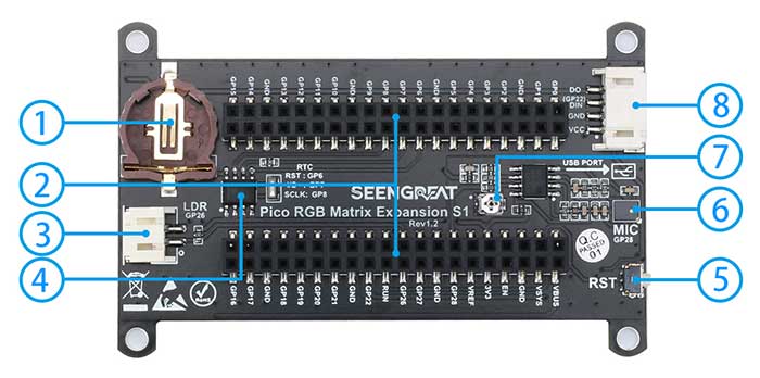
①CR1220 Button Battery Holder
②Raspberry Pi Pico Female Header
③Light-Dependent Resistor Connector
④DS1302 Real-Time Clock Chip
⑤Raspberry Pi Pico Reset Button
⑥Analog Silicon Microphone
⑦Silicon Microphone Amplification Adjustment
⑧WS2812 RGB Matrix screen Interface Connector
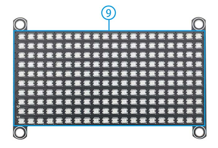
⑨0807 RGB LED Matrix screen
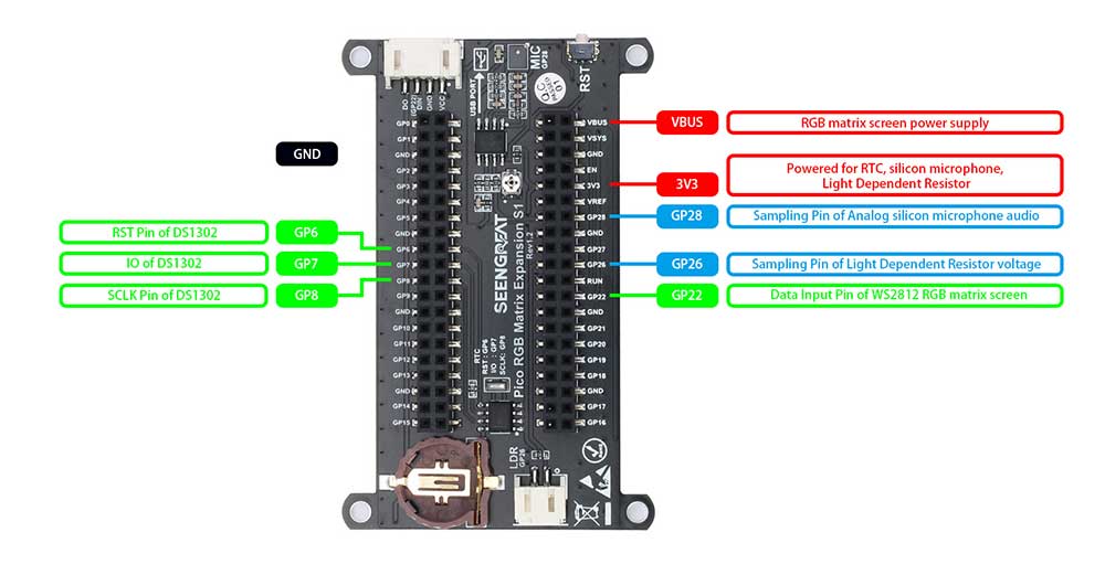
DS1302 Real-Time Clock Chip: Controlled via the GP6, GP7, GP8 (RST, IO, SCLK) pins of the Raspberry Pi Pico. This chip is powered primarily by the Raspberry Pi Pico, with a button cell battery on the expansion board providing backup power, enabling timing even when the Raspberry Pi Pico is not powered. This circuit can also display the time on the LED matrix, forming a simple electronic clock.
Analog Silicon Microphone Audio Sampling Circuit: This circuit is powered by the Raspberry Pi Pico and has high sensitivity, capable of capturing faint sounds. It outputs analog signals to the GP28 pin, allowing for music rhythm display on the LED matrix when combined with the Raspberry Pi Pico.
Light-Dependent Resistor: The expansion board also features a PH2.0 connector for inserting a light-dependent resistor. After inserting the light-dependent resistor, the board can sense changes in ambient light. This is a type of sensor; when the ambient light changes, the resistance of the resistor itself changes, decreasing with brightness. It outputs corresponding voltage changes, allowing for brightness control of the expansion board through programming.
Reset Button: The Raspberry Pi Pico lacks a reset button. This product adds a reset button so that users can reset or debug without frequently plugging and unplugging the Pico's USB cable.
Using Python Examples
1.Install Thonny
Thonny download link: https://thonny.org
2.After installing Thonny, with the Pico powered off, press and hold the BOOTSEL button on the Pico, then connect it to your computer via USB. Release the button, and a RPI-RP2 disk directory will pop up. Drag the micropython-firmware-Pico-w-130623.uf2 file from the Pico RGB Matrix Expansion S1 directory into the RPI-RP2 disk.
3.Right-click on DS1302.py under the Pico RGB Matrix Expansion S1 directory and open it with Thonny. Click on Tools -> Options. In the interpreter field, select MicroPython (Raspberry Pi Pico), and set the port (COMx: the port number may vary on different computers). Click OK to confirm.
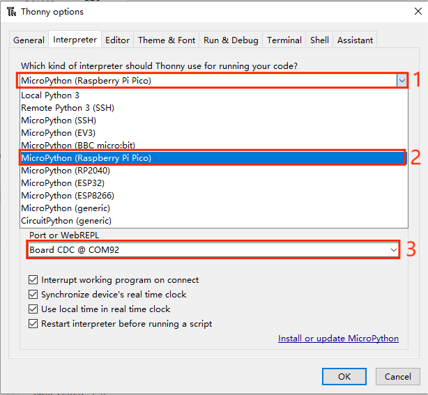
①Click here.
②Select "MicroPython (Raspberry Pi Pico)".
③Set the corresponding port here, and click OK to confirm.
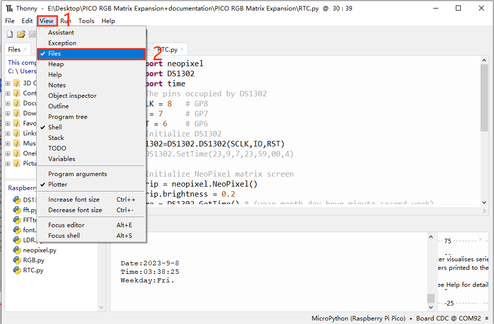
4.Open the View -> Files window, and upload the Lib library files to the Raspberry Pi Pico.
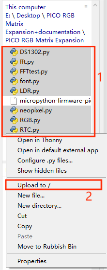
①Press Ctrl and select all .py files inside the Pico RGB Matrix Expansion S1 folder, as shown in Figure 2-4-2.
②Click here to save these files to the Raspberry Pi Pico.
5.Open the prepared RGB.py file, then click the "Run current script" button or press the F5 key to run the current script. Observe the display on the LED matrix.
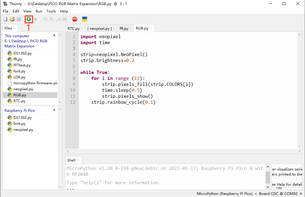
① Click here as shown in Figure 2-5 to run the example program and observe the display on the LED matrix.
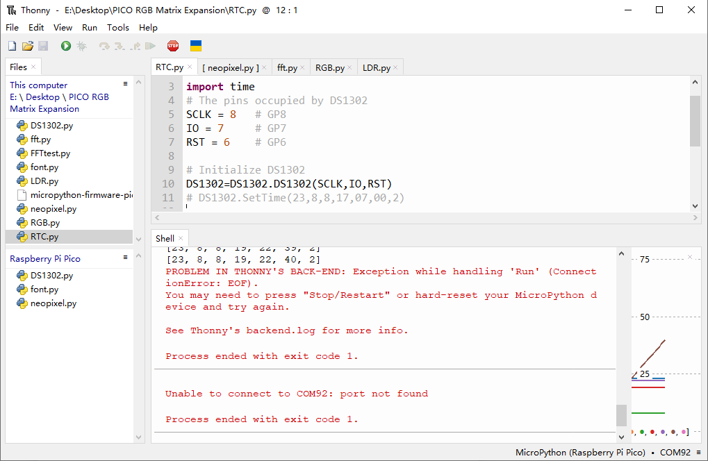
6.Insert the prepared button battery into the battery holder, open the RTC.py script, then click the "Run current script" button or press the F5 key to run the current script. Observe the display on the LED matrix.
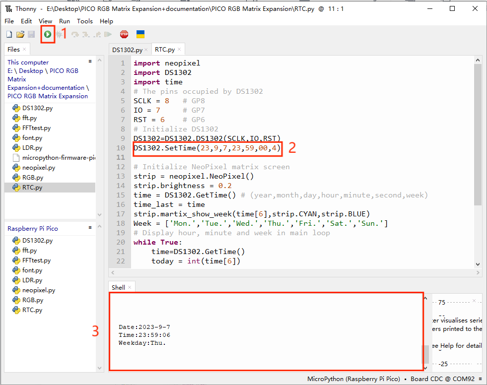
①Click here as shown in Figure 2-6 to run the example program.
②Observe whether the time display in the shell window is correct.
③Check if the time displayed in the shell window matches the set time.
Install the button battery on the expansion board, comment out the code for setting the time, and observe whether the timing function works properly after power off. If the time continues to increase as originally set, it indicates that the button battery is supplying power normally.
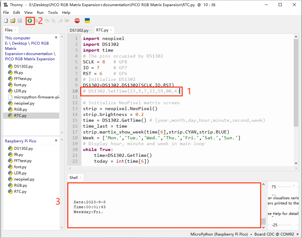
①Comment out the code at the location shown in Figure 2-7.
②Click here to run the example program.
③Observe whether the time in the shell window continues to increase before and after power off.
7.Open the fft.py script, then click the "Run current script" button or press the F5 key to run the current script. Generate some noise or play some music, and observe the LED matrix on the expansion board. The LEDs on the LED matrix correspond from left to right to low frequency to high frequency. See if the lights on the LED matrix rhythmically change with the sound.
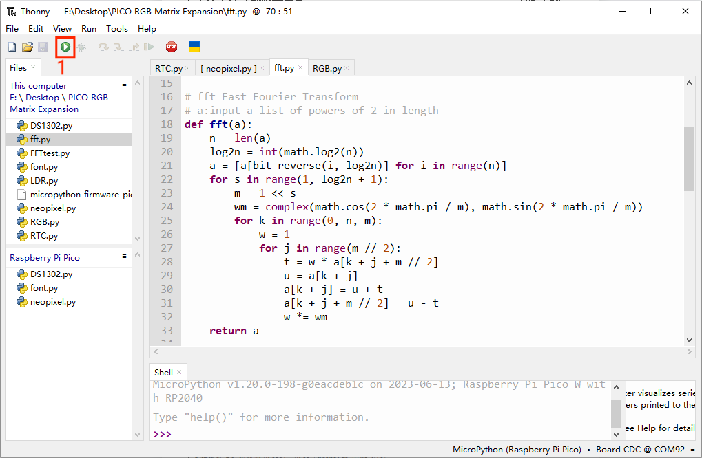
① Click here as shown in Figure 2-8 to run the example program.
8.Insert the light-dependent resistor into the female header labeled "LDR" on the expansion board.
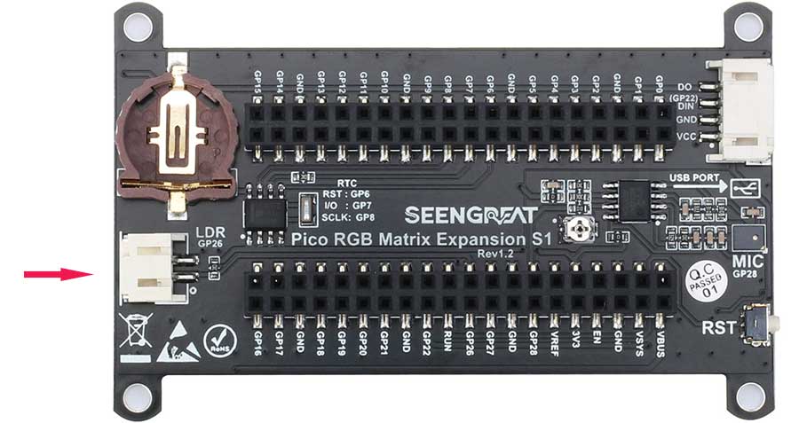
Open the LDR.py script, then click the "Run current script" button or press the F5 key to run the current script. Illuminate or place the light-dependent resistor in a dark place as appropriate, and observe whether the LED matrix brightens or dims with changes in ambient light.
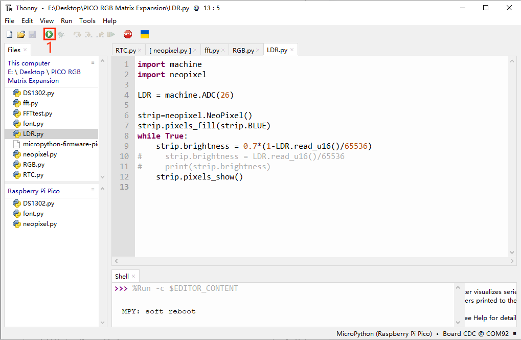
①Click here to run the example program.
9.Press the reset button on the side of the expansion board and observe whether the expansion board resets successfully.
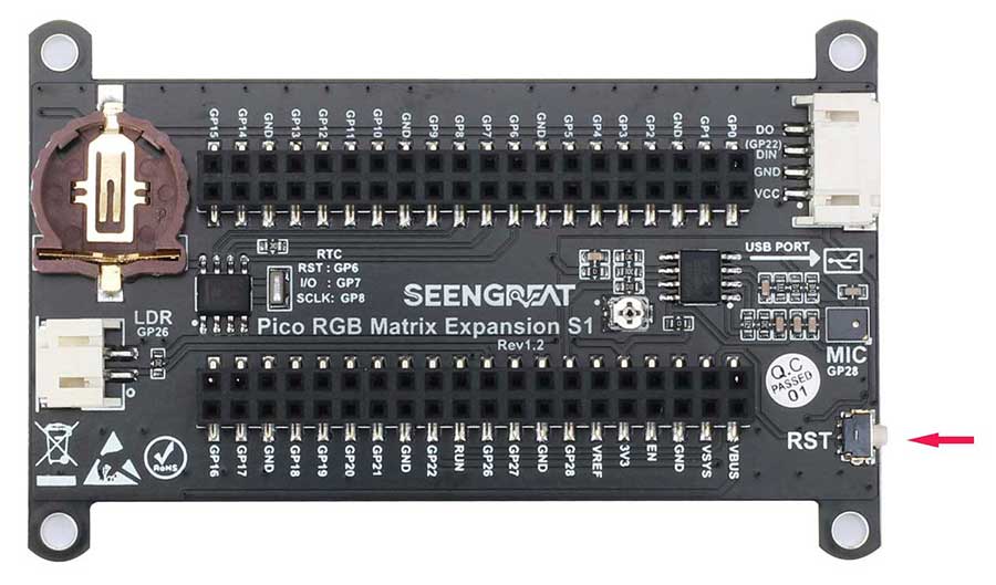
Reset Successful as Shown in Figure 2-12
Resources
Datasheets