Product Overview
This adapter module is a high-performance USB to RS232/485/TTL interface converter module. It uses the FT232RL chip as its core, supports the USB 2.0 standard, and enables bi-directional data transmission between USB and RS232/485/UART (TTL). The module is characterized by its user-friendly and stable performance, making it widely applicable in various industrial electronic devices. It can be installed using a DIN rail or screw fastening method. Users can utilize these interfaces to communicate with other devices, facilitating the transmission and reception of information. Additionally, this product supports multiple operating systems, including Windows, Linux, Android, and MAC OS.
Product Features
- Onboard integrated power isolation, no additional power supply required for the isolated end
- Onboard integrated digital signal isolation, characterized by high reliability, strong anti-interference, and low power consumption
- User-friendly communication interfaces, smooth and robust USB-B and RS232 interfaces, RS485 and UART (TTL) utilizing standard 5.08mm pitch pluggable terminal blocks
- Onboard TVS (Transient Voltage Suppression) diodes effectively suppress surge voltage and transient spikes in the circuit, providing lightning and electrostatic protection
- The module supports multiple operating systems and development platforms, including Windows, macOS, Linux, and Android.
- Onboard power, TXD, RXD, and VCCIO (TTL logic level) indicators for status indication
- Onboard UART (TTL) level switching switch, enabling convenient and quick switching between 3.3V and 5V
- 120-ohm switching switch for the RS485 interface, allowing convenient and quick switching
- Designed for DIN-rail installation as well as screw-fixed structures, catering to a wider range of application scenarios.
Product Parameters
| Dimensions | 97mm (Length) x 76.5mm (Width) x 20mm (Height) | |
| USB Port | Operating Voltage | 5V |
| Connector | USB Type-B | |
| Interface Protection | TVS diodes, self-recovery fuses | |
| RS232 Interface | Connector | DB9 male head |
| Interface Protection | Bidirectional TVS, ESD protection | |
| Transmission Mode | Point-to-point | |
| Transmission Rate | 300bps ~ 921600 bps | |
| RS485Interface | Connector | 5.08mm terminal block |
| Interface Protection | Lightning protection, surge protection, TVS diode, ESD protection | |
| Direction Control | Hardware automatically detects and controls the data transmission direction | |
| Transmission Mode | Point-to-multipoint | |
| Transmission Rate | 300bps ~2 Mbps | |
| UART(TTL) | Connector | 5.08mm terminal block |
| Operating Voltage | 3.3V/5V | |
| Interface Pins | TXD、RXD、GND、VCCIO | |
| Interface Protection | Clamping protection diode | |
| Transmission Mode | Point-to-point | |
| Transmission Rate | 300bps ~2 Mbps | |
| Indicators | PWR | Power indicator, lights up when powered via USB |
| TXD | USB data transmission indicator, lights up when data is being sent | |
| RXD | USB data reception indicator, lights up when data is being received | |
| VCCIO | Lights up to indicate that the UART (TTL) voltage is 5V, off indicates 3.3V voltage for UART (TTL). | |

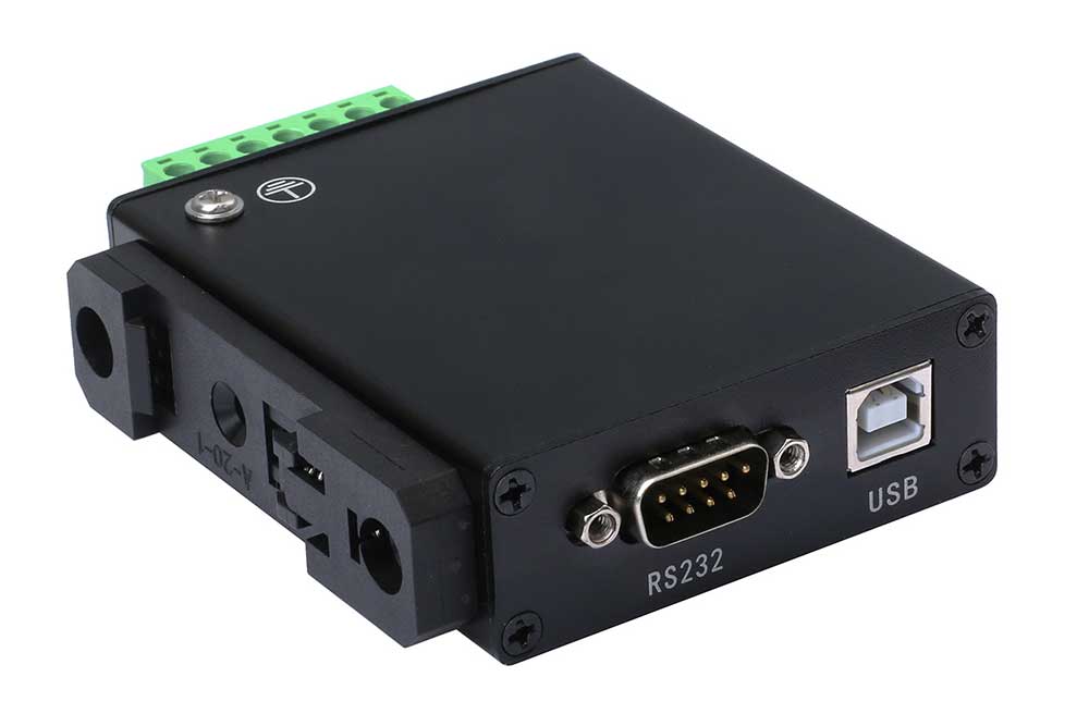
Resource overview diagram
Resource introduction as shown in the following figure.
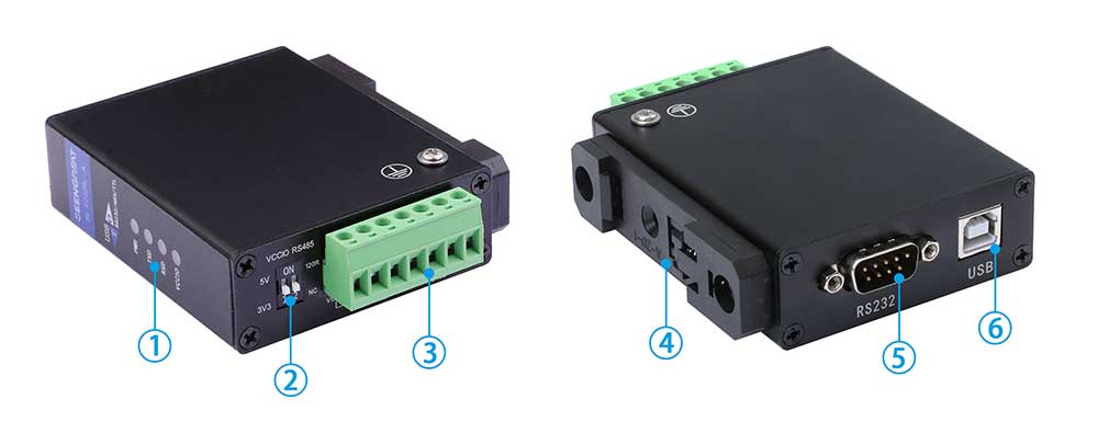
① Indicators
② VCCIO, 120R Selection Switch
③ UART (TTL) and RS485 Interface Terminal block
④ Rail connection fixture
⑤ RS232 Interface DB9 Connector
⑥ USB-B Connector
Usage
Interface Usage Instructions
RS232 Wiring Instructions
The RS232 interface uses a DB9 male connector, and the pin signal definitions are as shown in Figure below:
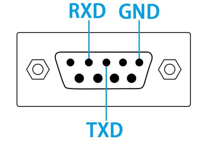
Users can directly connect an RS232 DB9 female device to the RS232 interface for testing. The TXD and RXD pins of the test device need to be cross-connected with the DB9 male connector of the SG-C232RL-A.
UART(TTL)Wiring Instructions
When the VCCIO DIP switch is set to 3.3V, the logic level for VCCIO, TXD, and RXD is 3.3V. When the VCCIO DIP switch is set to 5V, the logic level for VCCIO, TXD, and RXD is 5V. Connect the 7-pin 5.08mm terminal block to the SG-C232RL-A module. The wiring definition for the UART interface and the test device is as follows:
TXD------RXD
RXD------TXD
GND------GND
RS485 Wiring Instructions
When the RS485 DIP switch is set to 120R, it means that a 120-ohm resistor is connected between the A and B data lines. When set to the NC position, it means that there is no 120-ohm resistor connected between the A and B data lines, allowing users to choose freely.
Connect the 7-pin 5.08mm terminal block to the SG-C232RL-A module. The wiring definition for the RS485 interface and the test device is as follows:
A------A
B------B
GND----GND
Windows Driver Installation
FT232 has two types of drivers: VCP (Virtual COM Port) and D2XX.
1)VCP (Virtual COM Port) driver: Recognized as a serial port on the PC, using serial port protocol.
2)D2XX driver: Recognized as a USB port on the PC, requires the use of API functions for operation.
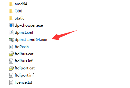
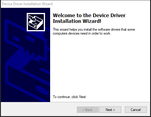
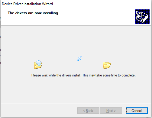
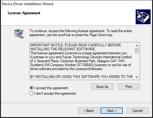
This product provides a VCP sample, so we will only discuss the installation of the VCP driver below. Taking the Windows 10 64-bit system as an example, the driver installation steps are as follows:
Driver download link:
https://www.seengreat.com/upload/file/115/FT232_Driver_win64.zip Users can also visit https://ftdichip.com/drivers/vcp-drivers/ for download and installation. The driver installation steps are shown in the following figure:
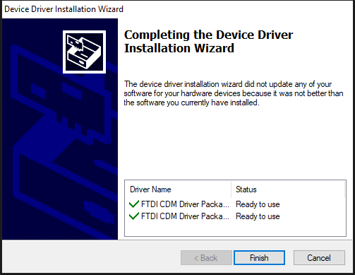
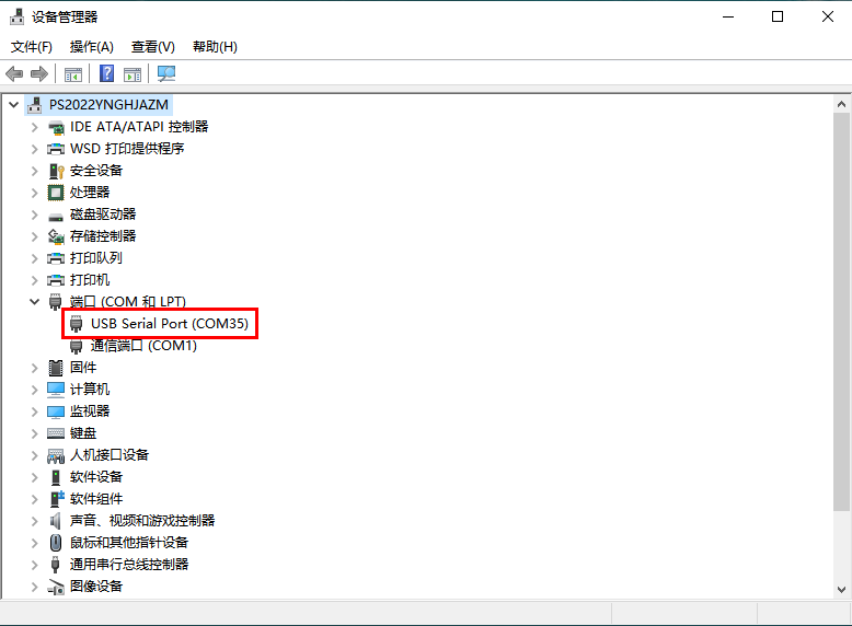
Once the driver is installed, when you connect the SG-C232RL-A to the computer using a USB cable, a "USB Serial Port" device will appear in the computer's Device Manager under Ports (COM & LPT), as shown in below:
Communication Test
The wiring diagram for the test is shown in Figure below.
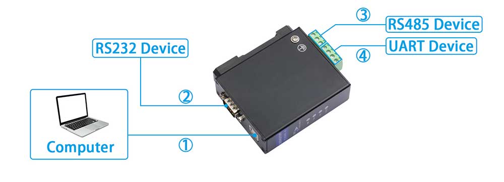
①、USB-A to USB-B cable
②、DB9 connection cable (pin signal definitions can be found in Figure 5)
③、RS485 connection cable (wiring definitions refer to section 2.1.3)
④、UART connection cable (wiring definitions refer to section 2.1.2)
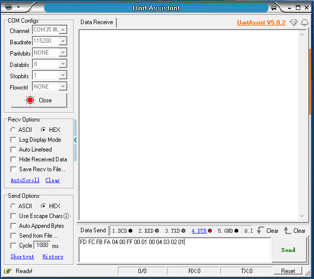
After making connections as shown in either method (②, ③, or ④) in Figure 12, open the serial port debugging assistant on the computer, as shown in Figure 13. You can proceed with data communication testing from this point onwards.
Resources
Data Sheet
Driver software