Product Overview
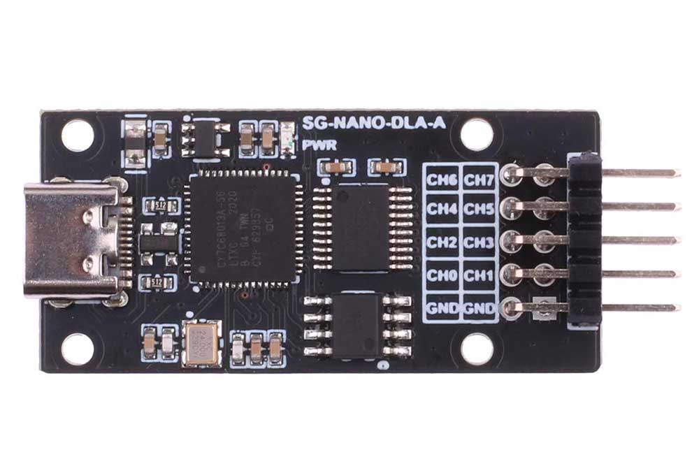
This product is a mini logic analyzer with a compact and exquisite appearance. It offers rich functionality and supports a maximum sampling rate of up to 24MHz (on the Linux platform). It also supports the analysis of over a hundred different protocols, making it suitable for the daily development and debugging needs of electronic engineers. It can be used in various scenarios such as system timing analysis, performance analysis, and signal debugging.
Product Parameters
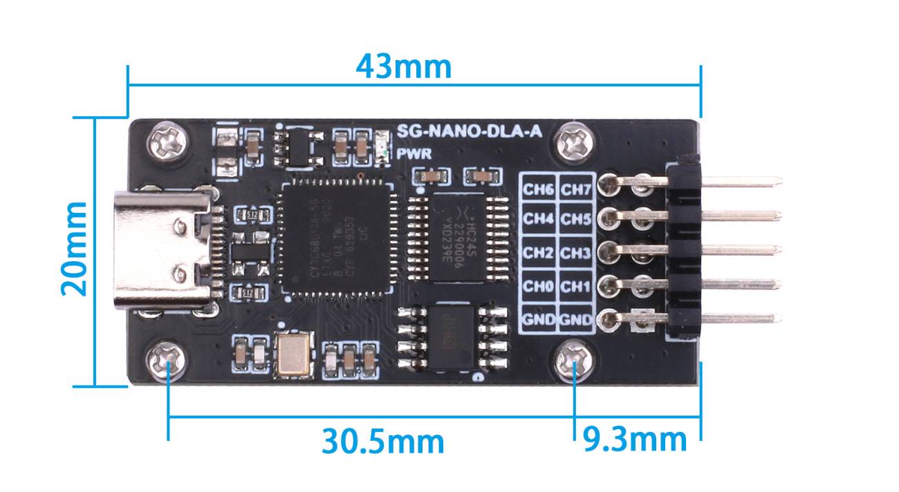
| Dimensions | 50mm (Length) * 20.32mm (Width) |
| Weight | 4.8g |
| Processor | CY7C68013A |
| Signal Buffer | 74HC245PW |
| Number of Channels | 8 |
| Sampling Frequency | Up to 24MHz |
Resource Overview Diagram
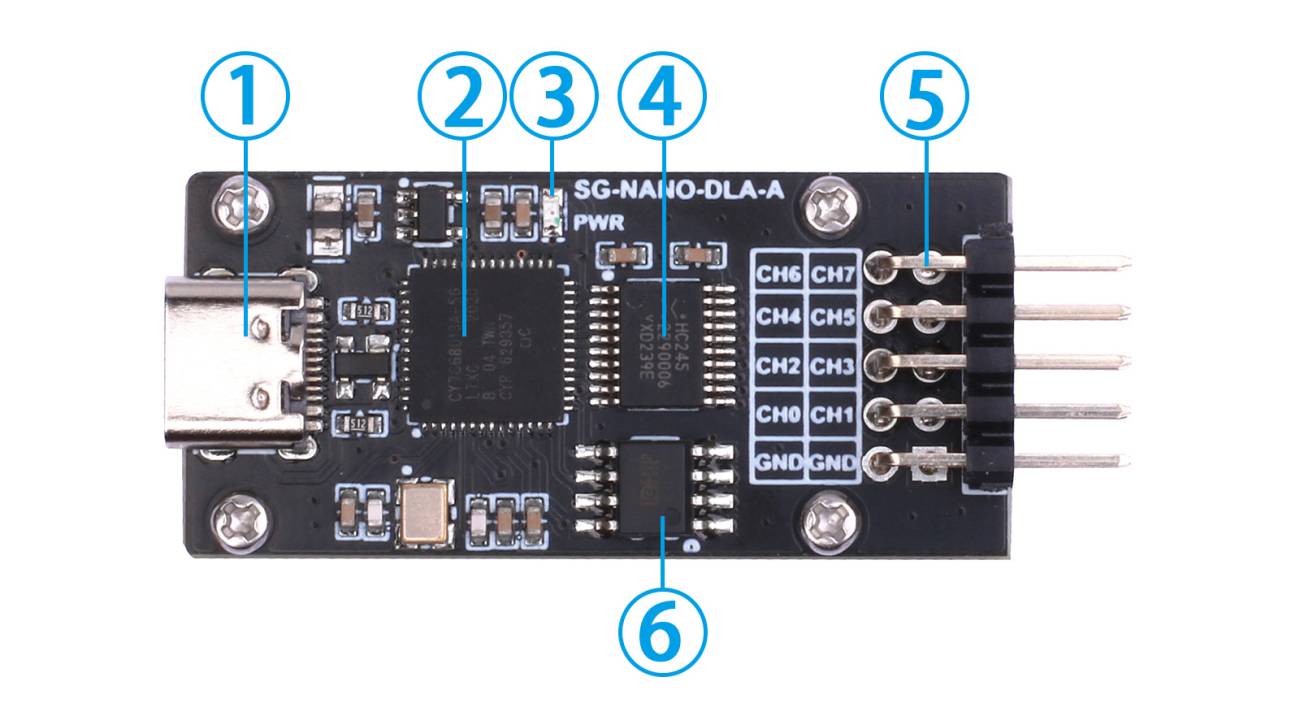
- ① Type-C USB Connector
- ② CY7C68013A
- ③ Power Indicator Light
- ④ 74HC245PW
- ⑤ Sampling Channel Connection Header
- ⑥ AT24C02
Usage
Hardware Introduction
This logic analyzer is designed based on CY7C6813A, and its hardware block diagram is shown in Figure 4 as follows:
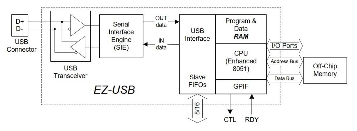
The EZ-USB FX2 series is produced by Cypress and is a microcontroller that integrates the USB 2.0 protocol. It provides an instruction set compatible with the 8051 microcontroller. The FX2LP series is a low-power version of the FX2 series, with CY7C68013A being one of the commonly used chips.
The internal components of the FX2LP chip mainly include:
- On-chip USB Physical Layer Transceiver with a speed of 480Mbps, Serial Interface Engine (SIE, part of the USB module).
- An 8051 core with a clock frequency of 48MHz.
- 256-byte register memory.
- Enhanced 4-clock cycle instructions.
- Firmware can be downloaded via USB.
- 4 FIFO/IO interfaces, data bus, address bus, and a general programmable interface.
- Instruction set and standard 8051 compatibility.
Software Introduction and Installation
This module uses Sigrok open-source software, which can be found at the official website https://sigrok.org.
The software download link is https://sigrok.org/wiki/Downloads. Sigrok is a combination of logic analyzer software that includes the following components:
- libserialport: A serial port communication library.
- libsigrok: The core functionality library.
- libsigrokdecode: Protocol library.
- sigrok-cli: Command-line software.
- PulseView: User interface software.
- sigrok-firmware-fx2lafw: Firmware used for microcontroller operation.
After downloading and installing the software, you will mainly use PulseView. When you connect this module, Sigrok will instruct CY7C68013A to use specific firmware to start, emulating a USB device, and enabling the collection of signal levels and data transmission.
The installation steps for PulseView are as follows:
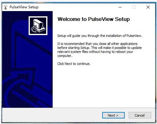
1、Users can download the appropriate PulseView installer package for their computer's operating system. For example, for a 64-bit Windows 10 system, you can download a file like "pulseview-0.4.1-64bit-static-release-installer.exe." Double-click on this file, and you will see the interface as shown in Figure 5 below.
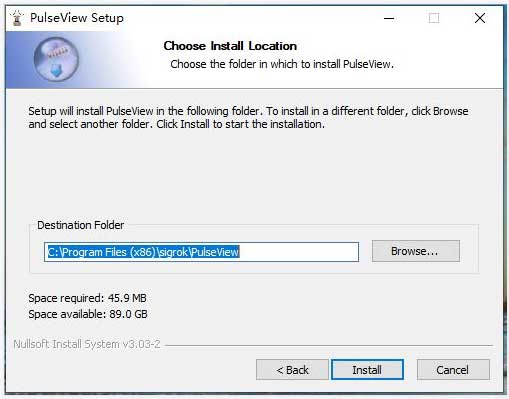
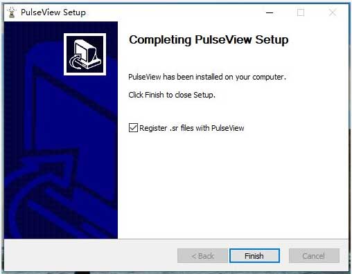
After that, you can click "Next" continuously until you see the interface in Figure 6. Then, click "Install" and wait for the installation to complete. Finally, click "Finish" as shown in Figure 7. At this point, the installation of PulseView is complete.
2、Install Logic Analyzer Driver
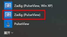
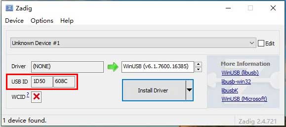
As shown in Figure 8, after successfully installing the software in the previous step, click on "Zadig (PulseView)" within the software. This will bring up the screen as shown in Figure 9. Pay attention to the "USB ID" in the red box, which should be "1D50 608C."
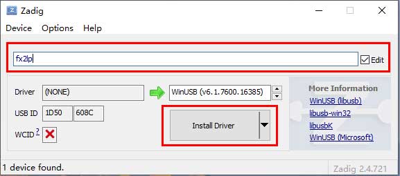
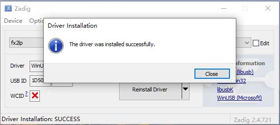
As shown in Figure 10, check the "Edit" option within the red box, then change the content in the box to "fx2lp." Finally, click "Install Driver." Wait for a few minutes, and you should see the interface as shown in Figure 11, indicating that the driver installation is complete.
Data Testing
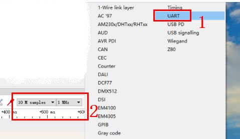
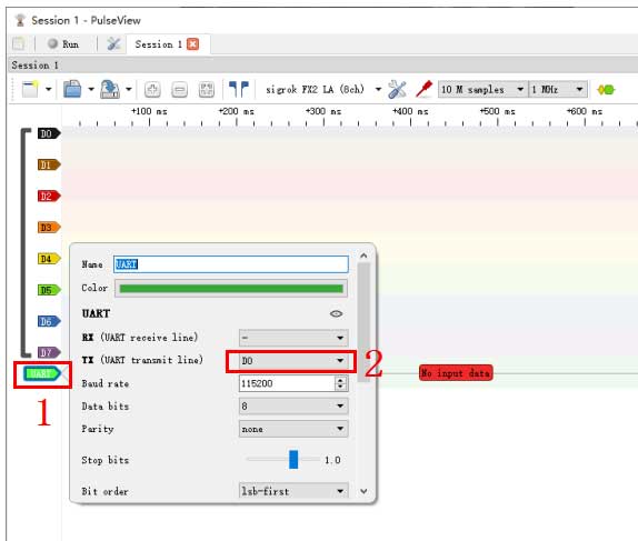
Click on 'PulseView' in Figure 8, then in the popup window, select 'sigrok FX2 LA (8ch)' as shown in '1' in Figure 12. Next, click on '2' in Figure 12, then select 'UART' as shown in '1' in Figure 13. Finally, set the sampling rate to the value shown in '2' in Figure 13.

The signal Dx on PulseView corresponds to the pin definitions on the SG-NANO-DLA-A board as shown in Table 1
| PulseView data cable | SG-NANO-DLA-A Pins | description |
|---|---|---|
| D0 | CH0 | Signal Analysis Input Channel0 |
| D1 | CH1 | Signal Analysis Input Channel 1 |
| D2 | CH2 | Signal Analysis Input Channel2 |
| D3 | CH3 | Signal Analysis Input Channel 3 |
| D4 | CH4 | Signal Analysis Input Channel 4 |
| D5 | CH5 | Signal Analysis Input Channel 5 |
| D6 | CH6 | Signal Analysis Input Channel 6 |
| D7 | CH7 | Signal Analysis Input Channel 7 |
| GND | Power Ground, should be common ground with the tested signal |
Table 1
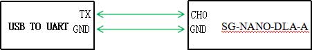
Connect the USB-to-UART (TTL) board and the SG-NANO-DLA-A to the computer using USB cables separately. Then, use DuPont wires to connect the TX pin on the USB-to-UART board to CH0 on the SG-NANO-DLA-A board, and connect GND to GND, as shown in Figure 14 below
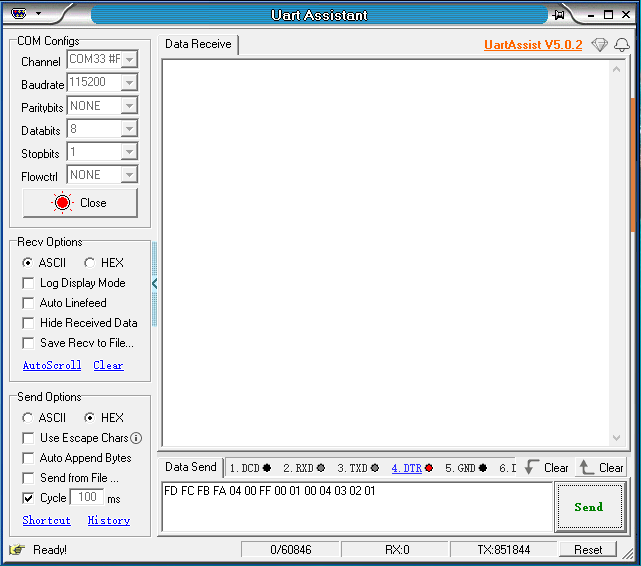
Double-click to open the serial port debugging assistant UartAssist.exe. In the Channel section, select the COM port of the USB-to-UART board, and configure other settings as shown in Figure 15. Finally, click 'Send' to continuously transmit data.
Click on 'UART' at '1' in Figure 16, then set the corresponding pin for TX, such as setting TX to D0 as shown at '2' in Figure 16. Of course, users can also set it to other pins, just ensure that the TX pin on the USB-to-UART board is connected to the corresponding signal input pin on the SG-NANO-DLA-A (refer to Table 1 for reference).
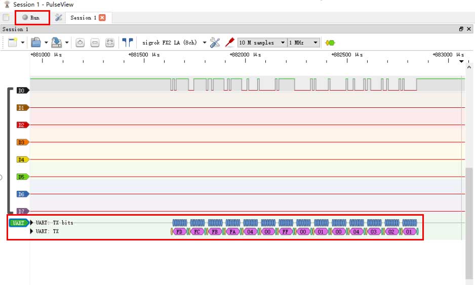
Then, click on 'Run' in PulseView (as indicated by the red box in the top-left corner of Figure 17). At this point, the system will start collecting logic signals. After collecting data for a while (e.g., a few seconds), click on the 'Stop' button, and examine the data analysis results on TX (D0), as shown in the red box at the bottom of Figure 17. It should match the data sent as shown at the bottom of Figure 15.
Resource
Data Sheets
Software