Product Overview
This product is a Micro:bit expansion board designed with PCA9685 as the core chip, integrating multi-channel motor and servo drives, full-color RGB LEDs, Sound volume level detection, 18650 battery management circuit, buzzer, etc., and from Micro:bit Lead out some GPIOs to support common electronic modules on the market; 18650 battery management circuit integrates lithium battery boost, charging management and protection chips, and supports micro USB interface charging at the same time. We provide python and makecode demo codes.
Product parameters
| Dimensions | 77.80mm x 57mm |
| Weight | 33.6g |
| Power Supply | 5V (3.5mm-2P terminal) or 3.7V~4.2V (18650 lithium battery) |
| Operating Voltage | 3.3V/5V |
| External power input | KF128L-3.5-2P(DC5V) |
| Charging batteries | Micro USB(DC5V) |
| GPIO expansion quantity | 8 |
| Number of RGBLEDs | 7 |
| Buzzer | 1 |
| I2C interface | 1 |
| Number ofservo drivers channels | 8 |
| Number of motordrivers channels | 4 |

Resource Profile
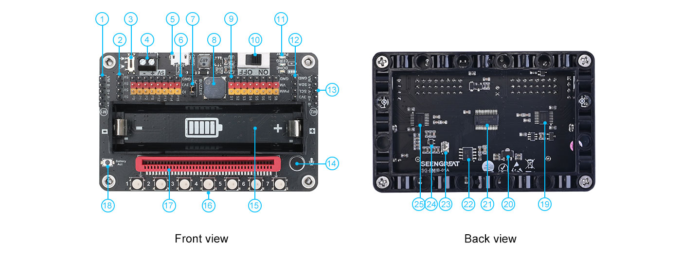
- 1. Motor 1 header
- 2. 5V header
- 3. Onboard buzzer switch
- 4. 5V input terminal
- 5. USB charging port
- 6. Lead out part of GPIO and 3.3V, GND
- 7. Microphone volume selection connection pin, short circuit means connected to P1 pin, open circuit means not connected to P1
- 8. Onboard buzzer
- 9. 8 sets of servos driver header
- 10. Power switch
- 11. LED indicators, from top to bottom are power indicator, battery charging indicator, battery fully charged indicator
- 12. Lead out I2C pin header
- 13 Motor 2 header
- 14. Microphone
- 15. 18650 battery holder
- 16. 7 WS2812B full-color RGB LEDs
- 17. Micro:bit edge connector
- 18. 18650 battery activated button
- 19&25. Dual-channel H-bridge motor driver chip AT8833
- 20. 5V to 3.3V chip: AMS1117-3.3
- 21. PCA9685
- 22. Lithium battery charging management chip: TP4056
- 23. Microphone volume gain adjustment resistor
- 24. Microphone preamplifier chip MAX4466
Usage
Python version code test
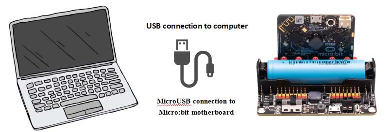
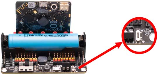
Use a USB cable to connect the micro:bit mainboard to the computer, and then insert the micro:bit mainboard into the slot on the SG-EMIB-01A board (see 17 in resource profile);
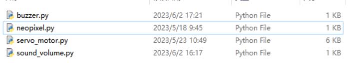
There are 4 codes in the python version, which are the buzzer test buzzer.py, the full-color RGB LED WS2812 test neopixel.py, the servo motor test servo_motor.py, and the volume detection sound_volume.py, as shown in Figure below:
Buzzer test
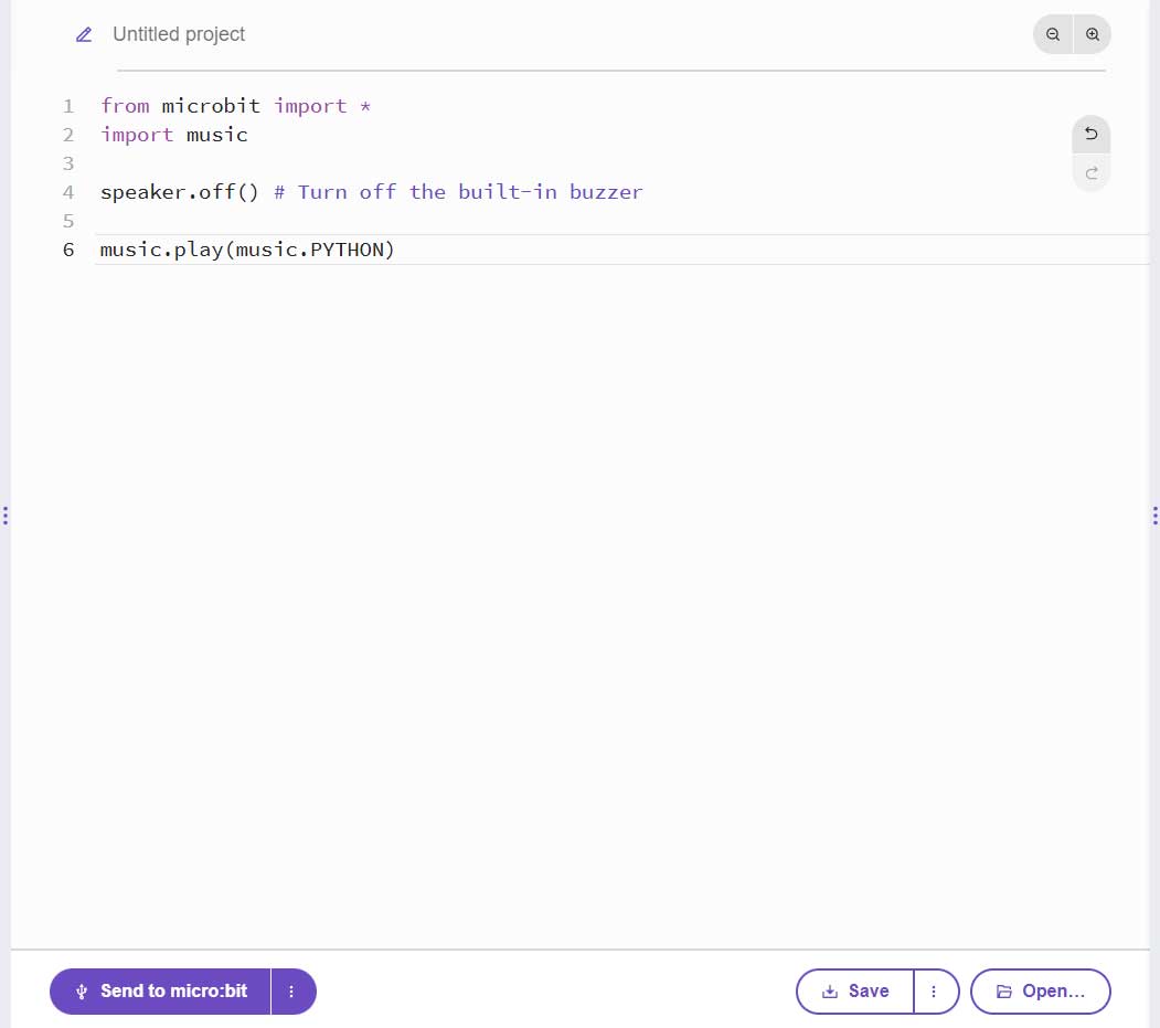
The buzzer is connected to the P0 pin, open Micro:bit's online code writing platform: http://python.microbit.org/, and then expand the buzzer.py in the demo codes folder, the content is as follows;
from microbit import *
import music
speaker.off() # Turn off the built-in buzzer
music.play(music. PYTHON)
And copy the content to the code writing window, as shown below:
Then click "Send to micro:bit" and wait until the transfer is complete to hear the buzzer beeping. Toggle the status of the buzzer switch to turn the sound on or off.
Full-color RGB LED WS2812 test
The RGB LED data input is connected to the P16 pin, open the neopixel.py file in the demo codes folder, the file content is as follows;
Copy the content to the code writing window, and then click "Send to micro:bit"
# Imports go at the top
from microbit import *
import neopixel
import time
import random

np = neopixel. NeoPixel(pin16, 7)

# Code in a 'while True:' loop repeats forever
while True:
   np[0]=(255,0,0)
   np[1]=(127,127,0)
   np[2]=(0,255,0)
   np[3]=(0,127,127)
   np[4]=(0,0,255)
   np[5]=(127,0,127)
   np[6]=(127,127,127)
   np.write()
   np.show()
   time.sleep(1)
   for i in range(7):
   np[i] = (random.randint(0,255), random.randint(0,255), random.randint(0,255))
   np.write()
   np.show()
   time.sleep(1)
Copy the content to the code writing window, and then click "Send to micro:bit", as shown below
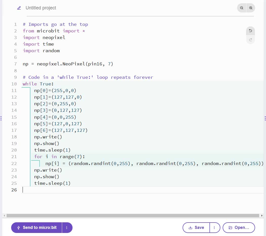
Wait for the transfer to complete and you will see 7 RGB LEDs flashing at intervals of 1 second.
Sound volume level detection test
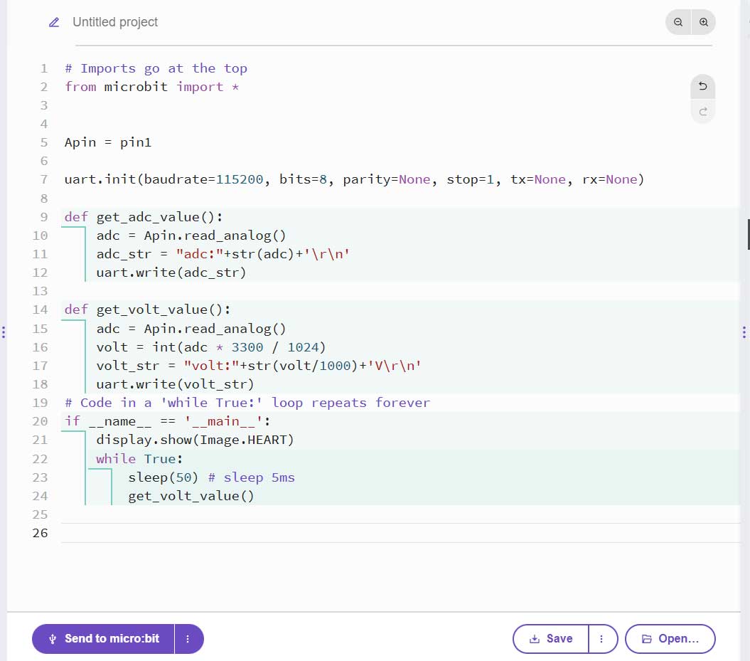
Pin header J5 (see ⑦ in Resource profile) is the connection pin for microphone volume selection. Short circuit means it is connected to P1 pin, and open circuit means it is not connected to P1. The default state is short circuit, that is, the microphone volume input is connected to P1 pin.
Open the sound_volume.py file in the demo codes folder, the content is as follows;
# Imports go at the top
from microbit import *
Apin = pin1
uart.init(baudrate=115200, bits=8, parity=None, stop=1, tx=None, rx=None)
def get_adc_value():
adc = Apin.read_analog()
adc_str = "adc:"+str(adc)+'\r\n'
uart.write(adc_str)
def get_volt_value():
adc = Apin.read_analog()
volt = int(adc * 3300 / 1024)
volt_str = "volt:"+str(volt/1000)+'V\r\n'
uart.write(volt_str)
# Code in a 'while True:' loop repeats forever
if __name__ == '__main__':
display.show(Image. HEART)
while True:
sleep(50) # sleep 5ms
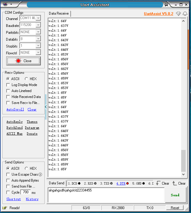
get_volt_value()Copy the content to the code writing window, then click "Send to micro:bit" and wait for the transfer to complete, as shown in Figure below;
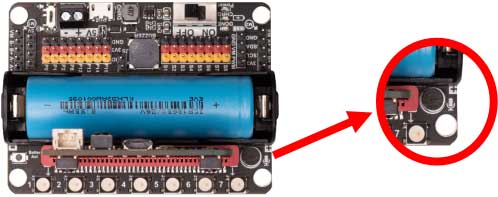
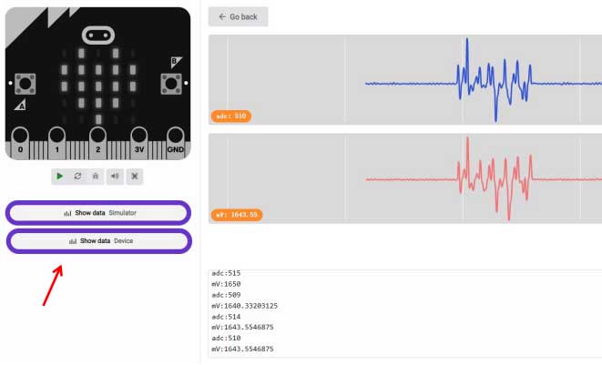
Then open the serial port debugging assistant, select the correct serial port number and baud rate, and then open the serial port. At this time, the PC will receive the corresponding volume and voltage data. Blow air into the onboard microphone or press continuously to see the data changing. The position of the microphone is shown in Figure below:
the serial debugging assistant is shown below:
Servo motor test
Open the servo_motor.py file of the demo codes file, and copy the content to the code writing window, then click "Send to micro:bit" and wait for the transfer to complete, as shown in Figure below;
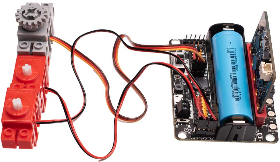
Then connect the servo to the 8-way servo header in sequence, and observe the direction of the servo. In addition, insert two DC motors to the two motor connectors on the left and right of the board, and check whether the motor is running according to the program. As shown in Figure below.
Graphical programming test
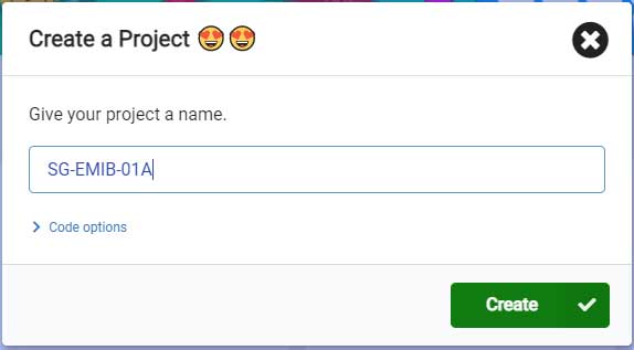
Open the graphic online programming website: https://makecode.microbit.org/, and then click "New Project" to create a new project.

Then enter the project name (customizable by the user), and click "Create", as shown in Figure below.
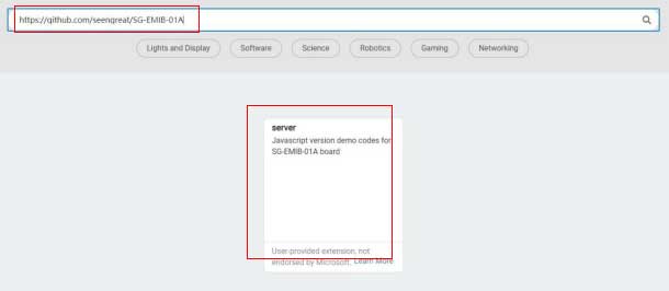
Click "Extensions" in the red box in Figure below, and then enter the link of the extension library in the search box: https://github.com/seengreat/SG-EMIB-01A, as shown in Figure below, Finally click on the extension library that appears in the center.
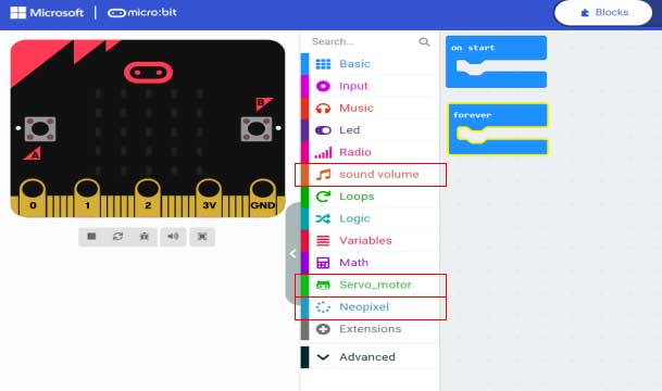
Then there will be three items shown in the red box in Figure below in the middle window: sound volume, Servo_motor, Neopixel.
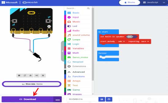
Buzzer test
The graphics code is shown in Figure below. After editing, click "Download" to download the code to the Micro:bit main board. After the transfer is complete, you can hear the buzzer making music, and switch the buzzer switch (The state of ③ of resource profile ) in can turn the sound on or off.
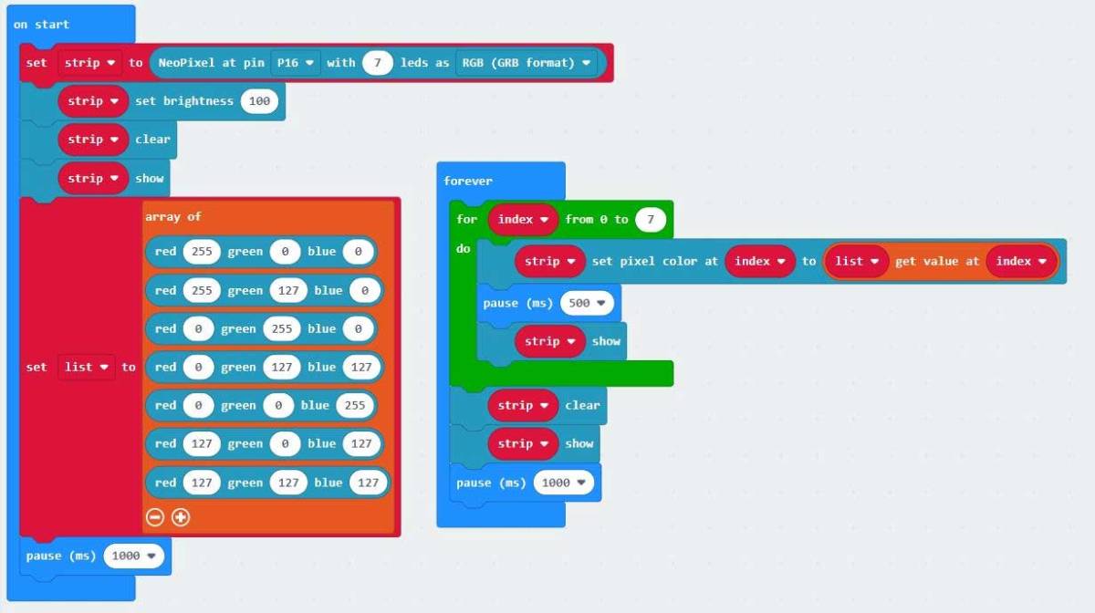
Full-color RGB LED WS2812 test
The graphics code is shown in Figure below. Click "Download" to download the code to the Micro:bit mainboard. Wait for the transfer to complete and you will see 7 RGB LEDs blinking at intervals of 1 second.
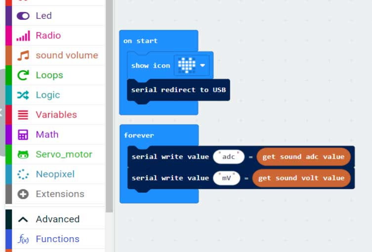
Sound volume level detection test
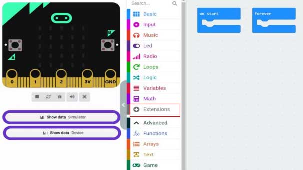
The graphic code is shown in Figure below, click "Download" to download the code to the Micro:bit , wait for the transfer to complete, and then click "Show Data Device" (as shown by the red arrow in Figure below), and the onboard microphone You can see that the data is changing by blowing air or pressing continuously.
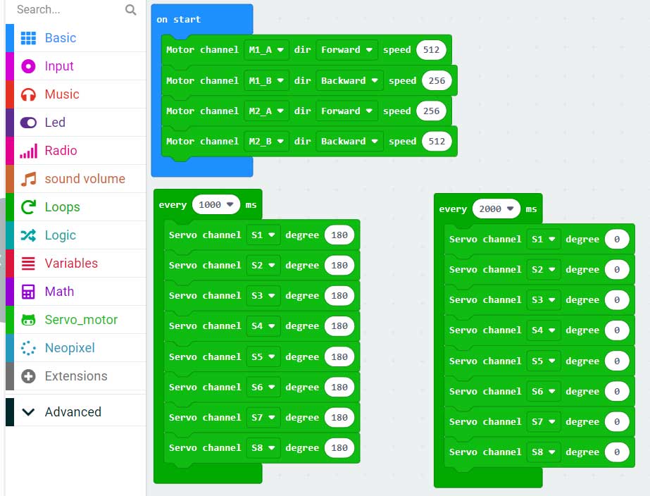
Servo motor test
The graphics code is shown in Figure below, click "Download" to download the code to the Micro:bit , wait for the transfer to complete. Then connect the servo to the 8-way servo header in sequence, and observe the direction of the servo. In addition, connect two DC motors to the two motor connectors on the left and right of the board.