Overview
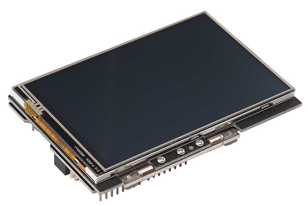
This product is a 4-inch resistive touchscreen display with a high-performance and user-friendly design based on the Arduino standard interface. It can be folded and parked at any angle up to 180 degrees, making it an ideal choice for Arduino developers and electronics enthusiasts. Combining resistive touchscreen technology with a high-resolution 4-inch colors display, it offers an intuitive user interface and rich display capabilities. We provide example codes for both the Arduino UNO and NUCLEO-F103RB versions.
Features
- 4-inch screen size, compact and portable, capable of folding at any angle up to 180°;
- The display boasts a high resolution of 480 x 320, presenting clear, sharp images and text;
- Utilizes resistive touch screen technology, enabling touch interaction, allowing users to input and control operations directly on the screen;
- Supports the Arduino standard interface and is compatible with the NUCLEO series of development boards;
- Provides open-source example programs suitable for the Arduino UNO and NUCLEO-F103RB development boards.
Specifications
| Driver Chip | LCD control chip ST7796S, touch panel control chip XPT2046 |
| Type | TFT |
| Communication Interface | SPI |
| Display Color | RGB ,65K colors |
| Resolution | 480 x 320 (Pixel) |
| I/O Voltage | 3.3V/5V |
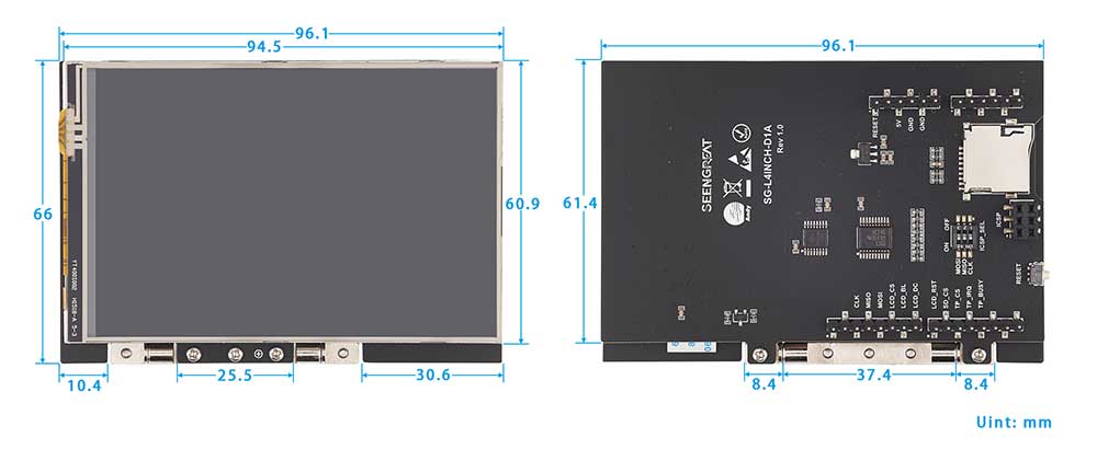
| Product Dimensions | 96mm x 66mm |
Interface Definition
| Label | Arduino UNO | NUCLEO | Description |
|---|---|---|---|
| 5V | 5V | 5V | 5V Power Input |
| GND | GND | GND | Power Ground |
| CLK | D13 | PA5 | SPI Clock |
| MISO | D12 | PA6 | SPI Master Input, Slave Output |
| MOSI | D11 | PA7 | SPI Master Output, Slave Input |
| LCD_CS | D10 | PB6 | LCD Chip Select |
| LCD_BL | D9 | PC7 | LCD Backlight |
| LCD_DC | D8 | PA9 | LCD Data/Command Selection |
| LCD_RST | D7 | PA8 | LCD Reset |
| SD_CS | D6 | PB10 | Micro SD Card Chip Select |
| TP_CS | D5 | PB4 | Touch Panel Chip Select |
| TP_IRQ | D4 | PB5 | Touch Panel Interrupt |
| TP_BUSY | D3 | PB3 | Touch Screen Busy Signal |
Resource Profile
Module Resource Profile is shown in the figure below:

- 1&2 Digital Pin Headers
- 3 Reset Button
- 4 ICSP Interface Selection DIP Switch
- 5 ICSP Female Header
- 6 SD Card Slot
- 7 Analog Pin Headers
- 8 Power Pin Headers
Example Program Usage
Arduino UNO
Hardware Interface Configuration Description
Module to Arduino UNO Pin Connection Definition Table:
| Label | Arduino UNO | Description |
|---|---|---|
| 5V | 5V | 5V Power Input |
| GND | GND | Power Ground |
| CLK | D13 | SPI Clock |
| MISO | D12 | SPI Master Input, Slave Output |
| MOSI | D11 | SPI Master Output, Slave Input |
| LCD_CS | D10 | LCD Chip Select |
| LCD_BL | D9 | LCD Backlight |
| LCD_DC | D8 | LCD Data/Command Selection |
| LCD_RST | D7 | LCD Reset |
| SD_CS | D6 | Micro SD Card Chip Select |
| TP_CS | D5 | Touch Panel Chip Select |
| TP_IRQ | D4 | Touch Panel Interrupt |
| TP_BUSY | D3 | Touch Screen Busy Signal |
Since this example program was verified on the Arduino UNO R3 board, the SRAM capacity of this board is only 2KB. Thus, the example program is divided into two project files: image display and touch.
Image Display Example Program Usage
1、Properly insert the module into the Arduino UNO development board.
2、For the image display example program "4inch_lcd_show_bmp.ino", before running this program, you should first copy the image files from the PIC folder to the SD card, which should be formatted as FAT. Then insert it into the SD card slot (see in item 6 of Resource profile).
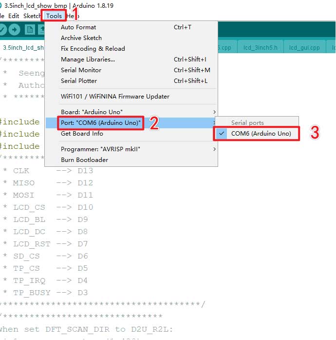
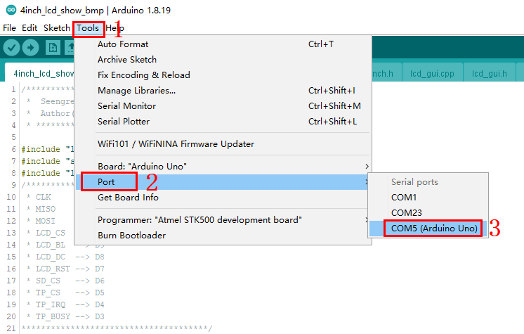
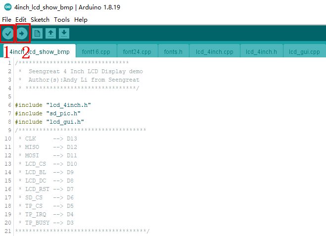
Select the board model and port number, as shown in the figure below:
3、Next click "Compile", and if there are no compilation errors, click "Upload" to load the example onto the development board, as shown in the figure below:
5、If you want the screen to display other images, you can store the images in the SD card. The image format should be BMP, with a bit depth of 24, and a resolution of 480 (Width) x 320 (Height). Also, modify the content of the "char file_name[4][20]" array in line 11 of the sd_pic.cpp file, i.e., change its content to the names of the images you want to display.
Touch Screen Example Program Usage:
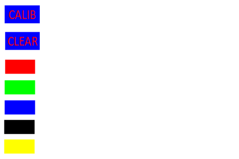
The touch screen example program "4inch_lcd_touch.ino", when uploaded to the Arduino UNO, will first display lines, rectangles, block fill, circles, and characters, and then enter the touch function display interface, as shown in picture below.
The "CALIB" button is for screen calibration functionality. Screen calibration parameters have already been filled in the TP_Init() function. Users can also update the values of tp_dev.xfac and tp_dev.yfac based on their own calibration results. After successful calibration, the message "Touch Screen Calibration OK!" will appear on the screen. If calibration fails, calibration will restart. If the user does not perform a calibration action within 10 seconds, the calibration process will automatically exit.
The "CLEAR" button is to clear the screen drawing board content, which can clear all the content drawn by the user on the screen drawing board. The red, green, blue, black, and yellow block buttons are for pen colors. The default pen color is black. If users want to switch colors, they can first press the corresponding color block button and then draw.
UNCLEO-F103RB
Hardware Interface Configuration Description
The module can be directly interfaced with the UNCLEO-F103RB motherboard. The wiring definitions are as shown in the table below:
| Label | UNCLEO-F103RB | Description |
|---|---|---|
| 5V | 5V | 5V Power Input |
| GND | GND | Power Ground |
| CLK | PA5 | SPI Clock |
| MISO | PA6 | SPI Master Input, Slave Output |
| MOSI | PA7 | SPI Master Output, Slave Input |
| LCD_CS | PB6 | LCD Chip Select |
| LCD_BL | PC7 | LCD Backlight |
| LCD_DC | PA9 | LCD Data/Command Selection |
| LCD_RST | PA8 | LCD Reset |
| SD_CS | PB10 | Micro SD Card Chip Select |
| TP_CS | PB4 | Touch Panel Chip Select |
| TP_IRQ | PB5 | Touch Panel Interrupt |
| TP_BUSY | PB3 | Touch Screen Busy Signal |
Example Program Usage Method
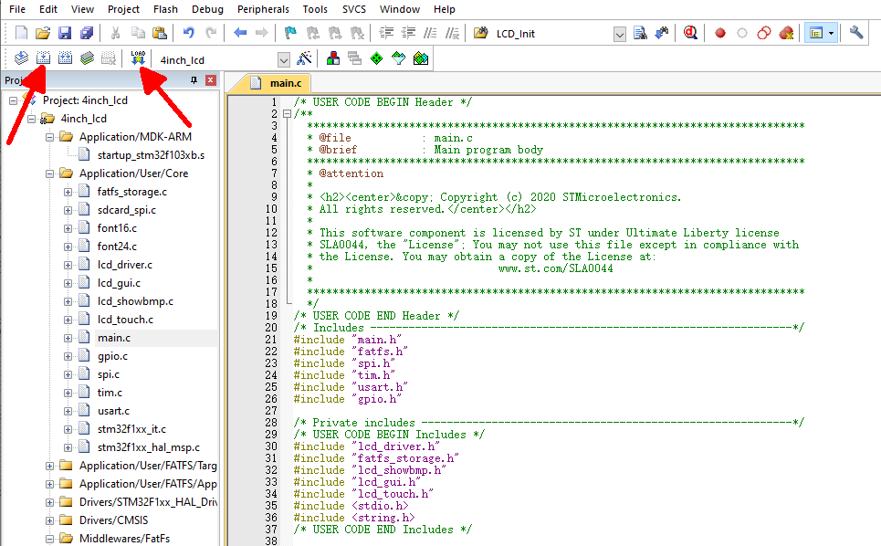
This example program is developed based on the HAL library. Open the project file located at STM32\4inch_lcd\MDK-ARM\4inch_lcd.uvprojx. First, click the "Build" button and wait for the compilation to complete. Then click the "Download" button, as shown in picture below. After the program is downloaded, the screen first displays some GUI function graphics, such as drawing lines, rectangles, circles, displaying characters, etc., then enters image display, and finally enters the touch function loop.
The example program has the same driver and program framework as the Arduino UNO platform. Because the STM32F103RB has sufficient SRAM and Flash capacity, all functionalities are integrated into a single project. At the same time, the SD card and its stored image format must be consistent with the Arduino UNO platform.