Overview
This product is a high-performance USB-to-serial port module, which uses PL2303GS chip as the core, supports USB 2.0 standard, and can realize two-way data transmission between USB and serial ports. The module is easy to use, stable and reliable, and is widely used in various electronic devices. Users can communicate with other devices through these pins to realize the transmission and reception of information. In addition, the product also supports a variety of operating systems, including Windows, Linux and MAC OS. It provides a standard UART(TTL) interface, including TX (transmit) and RX (receive) lines, and also has CTS (clear to send) and RTS (request to send) lines for more flexible control of data flow.
Product Parameters
| Supply voltage | 5V |
| Logic voltage | 3.3V/5V |
| Serial communication interface chip | PL2303GS |
| Baudrate | 12Mb/s(MAX) |
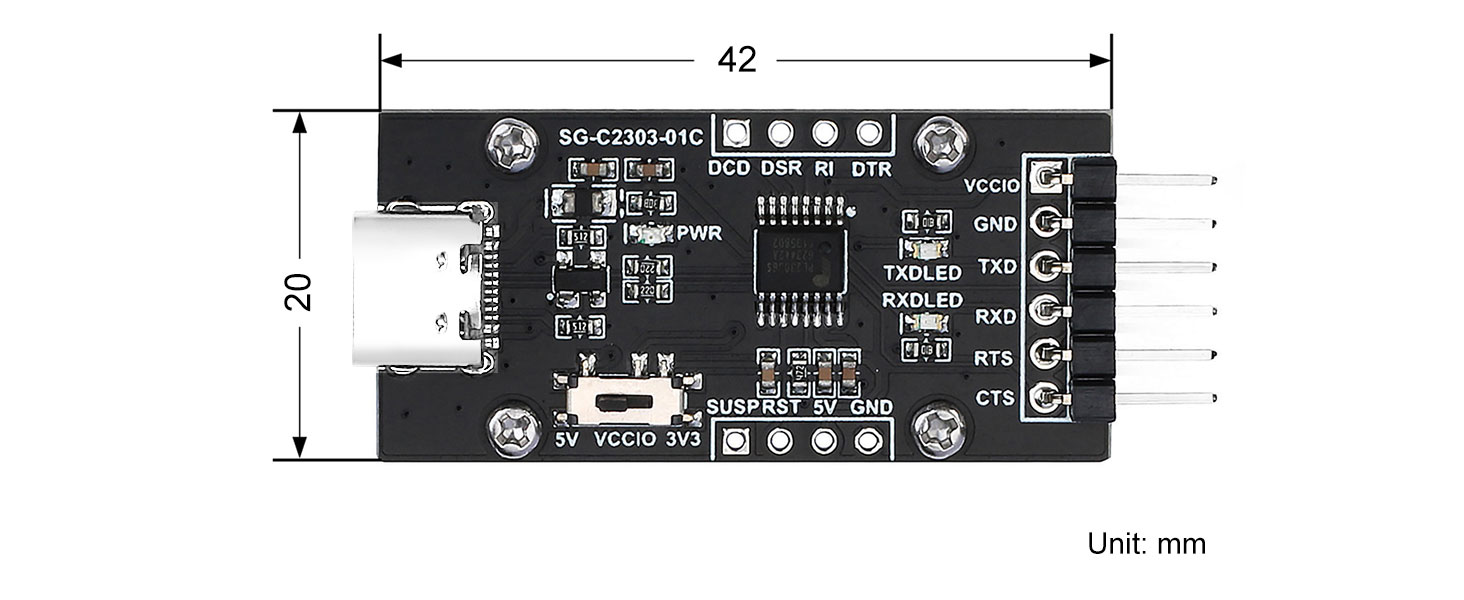
| Dimensions | 42mm(Length) x 20mm(width) |
| Weight | 4.0g |
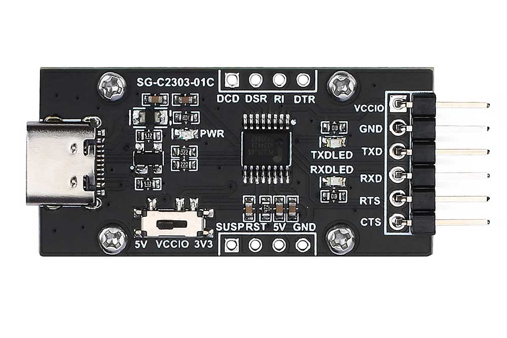
Resource Profile
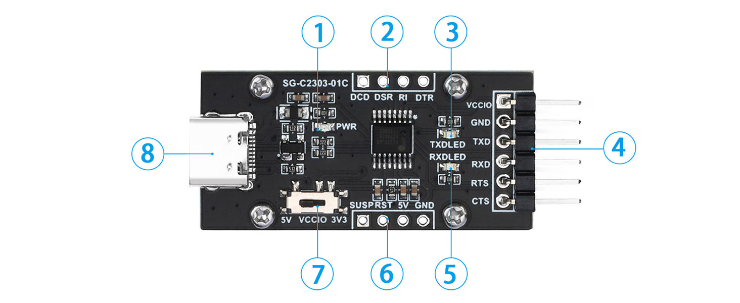
① Onboard power indicator
②&⑥ Reserve 2.54mm pitch control pin pad
③ TXD LED indicator
④ UART(TTL) header
⑤ RXD LED indicator
⑦ 3.3V/5V logic voltage switching slide switch
⑧ USB Type-C connector
Usage
UART interface description
| VCCIO | 5V or 3.3V(Toggle with slide switch) |
| GND | Ground |
| TXD | Serial data transmit pin, connect to MCU.RX |
| RXD | Serial data receive pin, connect to MCU.TX |
| RTS | Request to send, used to control data sending, connect to MCU.CTS |
| CTS | Clear sending for controlling data sending, connect to MCU.RTS |
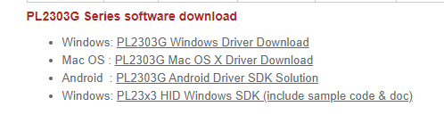
Driver installation
Open the following official website: www.prolific.com.tw/US/index.aspx
Then select "Products Application" -> "SIO(Smart-IO)" -> "USB to UART/Serial/Printer", and you can see the driver software download of the corresponding operating system at the bottom of the page, as shown in the figure below:
Raspberry Pi configuration and testing
Raspberry Pi Hardware Interface Configuration Instructions
Use a data cable to directly connect the USB connector of the Raspberry Pi, connect the other end of the data cable Type-C to the Type-C connector of the module, and then use a Dupont cable to connect the TXD and RXD of the module together, and run the following command on the Raspberry Pi terminal Check to see if the device is recognized.
lsusbAfter running the command, the Raspberry Pi terminal displays the following.
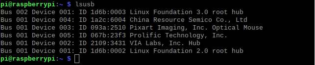 Then run the command to view the recognized serial port number.
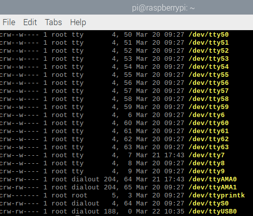
ls -l /dev/tty*The terminal displays the following,ttyUSB0 is the recognized serial port number;
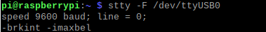
Run the command to view the baud rate of the serial port (note: the USB number here is written according to the USB identified above).
stty -F /dev/ttyUSB0The terminal displays the following:
Run the command to view the serial port connection information.
dmesg | grep ttyUSB0The terminal displays the following:

Enter the following code to test the UART to serial port module.
Demo code analysis:
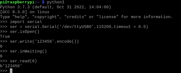
pi@raspberrypi:~ $ python3 # open editable interface
Python 3.7.3 (default, Oct 31 2022, 14:04:00)
[GCC 8.3.0] on linux
Type "help", "copyright", "credits" or "license" for more information.
>>> import serial # import the module
>>> ser = serial. Serial('/dev/ttyUSB0',115200,timeout = 0.5) #Set parameters: serial port number, baud rate, read time
>>> ser.isOpen() # determine whether the serial port is open
True # serial port is open return True, otherwise return False
>>> ser.write('123456'.encode()) # input data, data can be input multiple times
6# read returns the number of bytes written
>>> ser.inWaiting() #Read the total input bytes
6# return, display the accumulated number of bytes
>>> ser.read(6) #read six bytes, assuming a total of 24 bits of data are input, this time the first six bits will be output; if changed to ser.read(24) then only the input 24 bits will be output data
Computer and Raspberry Pi Connection Test
The computer is connected to the module through a USB data cable, and the module is connected to the Raspberry Pi through a Dupont cable. The wiring method is as follows:
Module -> Raspberry Pi
GND -> GND
TXD -> RXD
RXD -> TXD
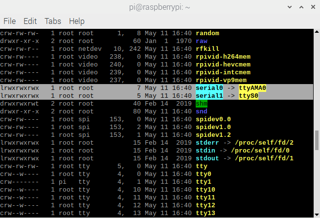
Run the command to view the serial port
ls -l /dev/*serial*The terminal displays the following

The default serial port is serial0 mapped to ttyS0, that is, the main serial port points to the mini serial port, but the efficiency of the mini serial port is low and unstable, so here we need to point the main serial port to the hardware serial port, which is ttyAMA0; enter the command in the Raspberry Pi terminal to open it. txt file.
sudo nano /boot/config.txtAdd the following two lines at the end of the .txt file.
dtoverlay=pi3-miniuart-bt
force_turbo=1
The terminal displays the following:
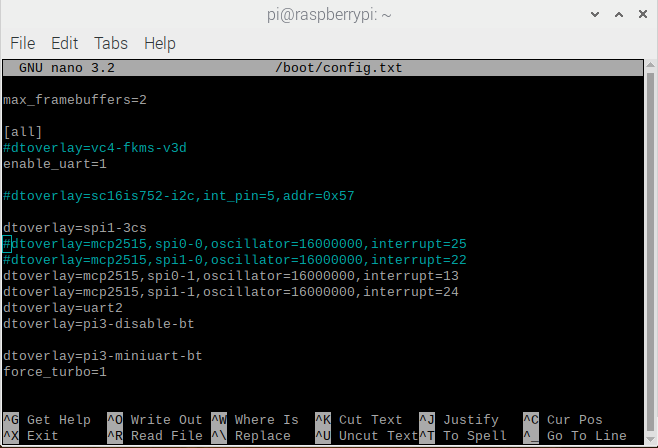
Then save and exit. At this time, open the terminal again and enter "ls /dev -al", you can see that the serial port mapping has been forcibly changed, and the main serial port Serial0 has pointed to the hardware serial port ttyAMA0.
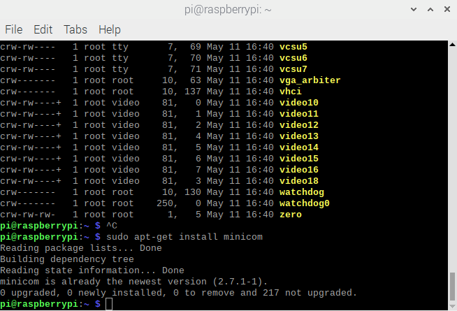
Computer and Raspberry Pi Connection Test
Open the terminal, enter "sudo apt-get install minicom" and wait for the installation to complete. After the installation is complete, the terminal displays the following:
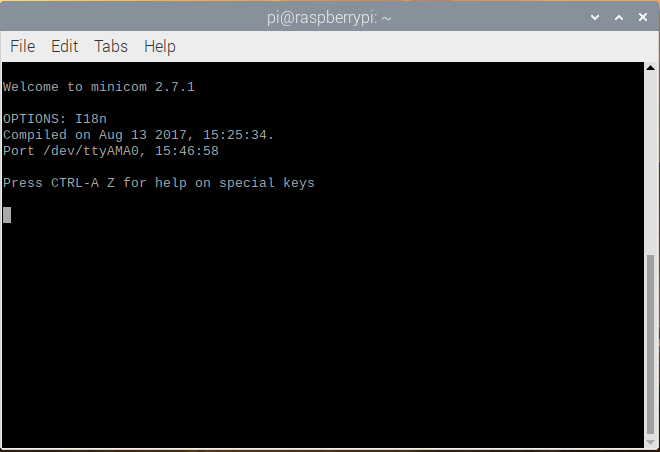
Enter the command in the terminal: "minicom -D /dev/ttyAMA0 -b 115200" to open the serial port assistant.
Here -D /dev/ttyAMA0 points to the serial port number we opened, which is the same as COM1. -b 115200 is the configuration baud rate. We can enter Ctrl+A in minicom to see it below. For our baud rate, if -b is not set, the baud rate will be 115200 by default.
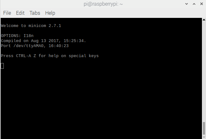
Run minicom -D /dev/ttyAMA0 -b 115200 to enter the serial port tool.
(1) First press Crtl+A in the minicom serial port, then click Z to enter the help option:
(2) Click O to enter the Configure Minicom option;
(3) Select the Serial port setup option, press F to change Hardware Flow Contorl to No; that is, disable the hardware flow, and then exit. All configurations have been completed here, and then you can verify it.
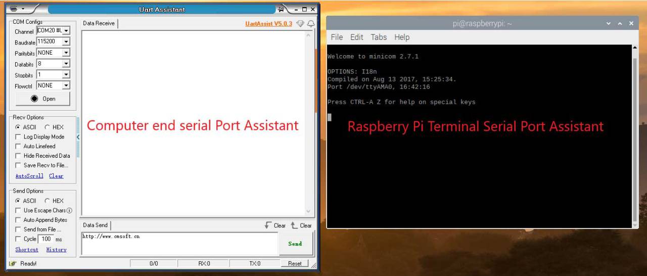
Go back to the computer side, open the serial port debugging assistant on the computer side, and set the serial port parameters at both ends to be the same;
If your minicom input is not displayed, press Crtl+A, then press E to open the echo function.
The computer side can send a series of data, but the Raspberry Pi side can only send data one by one, and will not automatically wrap;
Sometimes when you open the minicom serial port assistant under minicom, you will find that the keyboard fails. If you do not encounter this situation, you can skip this section.
Check the documentation and find this Note in the documentation:
Note: If you haven't configured minicom before (i.e: first use after installation), or if you find that your keyboard key presses are not sent to the RPi, you should make sure Hardware Flow Control is disabled. See Tedious Old-Fashioned Way Using
It reminds us to make sure to disable hardware control flow, and follow the documentation.
Resources
Data Sheet
PL2303 series chip and driverdownload:
www.prolific.com.tw/US/index.aspx