
 I. Introduction
1.1 Product Overview
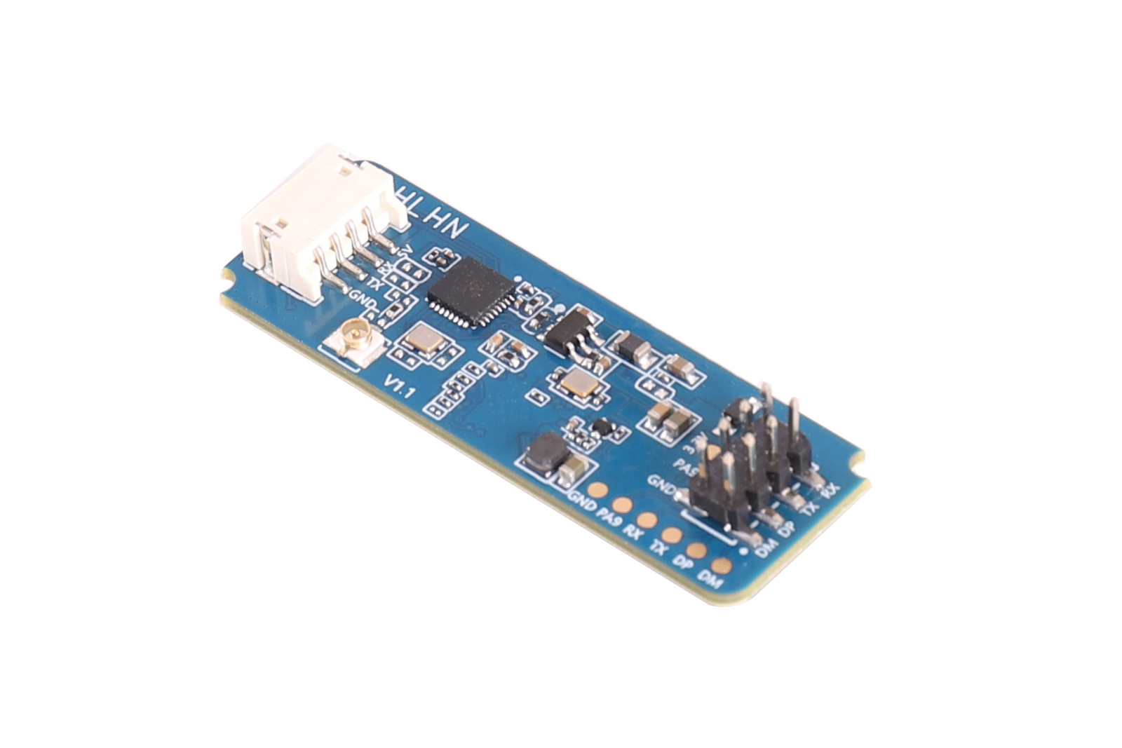
Moving target tracking refers to tracking the position of a moving target in real time within an area, enabling distance, angle, and speed measurement of the moving target in that area. The LD2450 is a moving target tracking sensor module, comprising minimalist 24GHz radar sensor hardware and intelligent algorithm firmware. This product is mainly used in ordinary indoor scenarios such as homes, offices, and hotels to achieve positioning and tracking of moving human bodies. The sensor hardware consists of an AIoT mmWave radar chip, a high-performance one-transmit-two-receive microstrip antenna, a low-cost MCU, and peripheral auxiliary circuits. The intelligent algorithm firmware adopts FMCW waveform and the radar chip's proprietary advanced signal processing technology. It supports serial port output of detection data, is plug-and-play, and can be flexibly applied to different smart scenarios and terminal products.
1.2 Product Features
- 24GHz ISM band
- Integrated intelligent mmWave radar chip and intelligent algorithm firmware
- Precise moving target positioning and tracking
- Maximum detection distance: 6 m
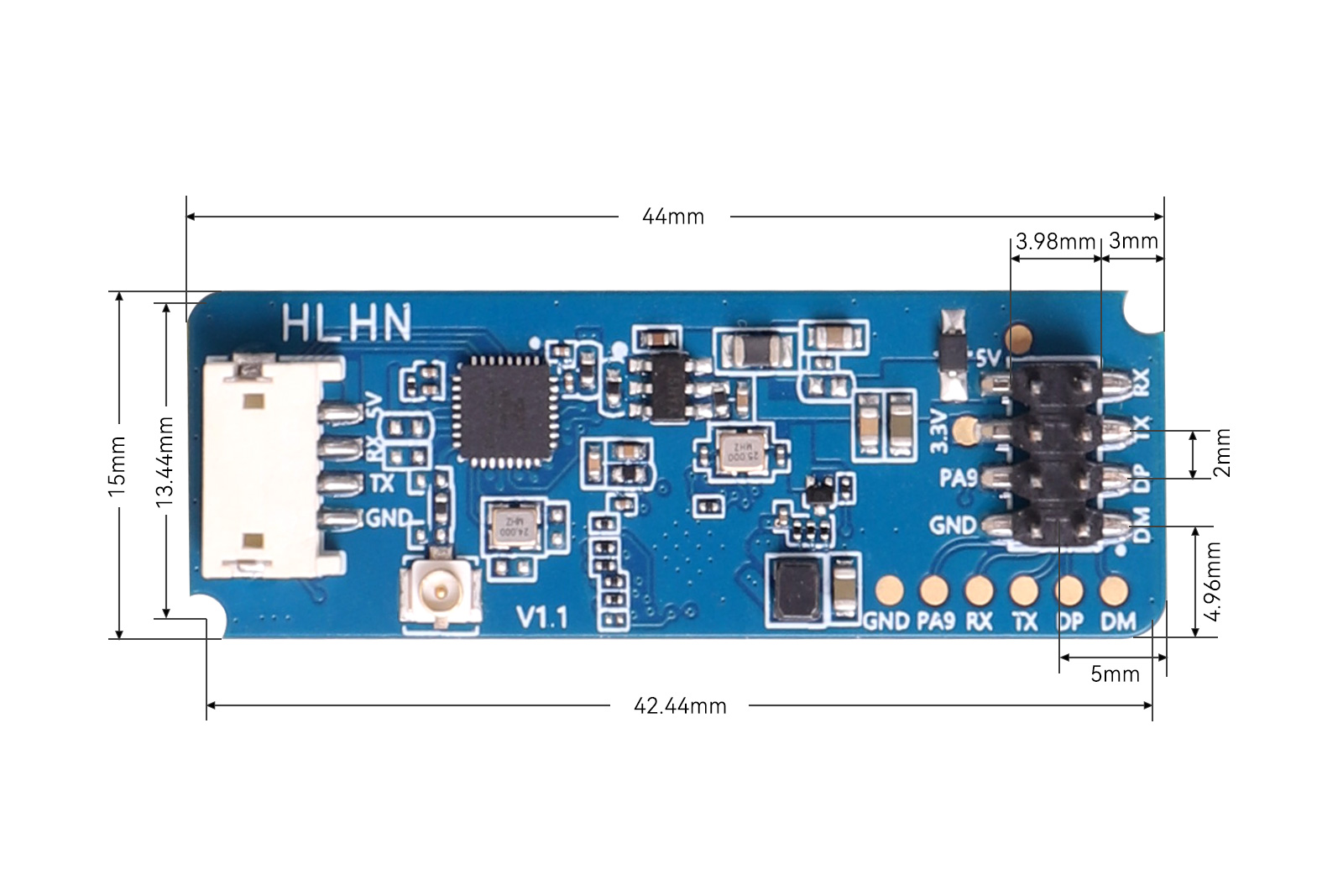
- Ultra-small module size: 15 mm × 44 mm
- Wall-mounted installation
- Azimuth angle: ±60°, elevation angle: ±35°
- Ultimate cost-effectiveness
- Multiple connection methods, with pin and socket interfaces
1.3 Product Advantages
The LD2450 human presence sensing module adopts 24GHz mmWave radar sensor technology. Compared with other products in the same series, it has obvious advantages in human presence sensing applications:
- In addition to being sensitive to moving human bodies, it can also sensitively detect micro-movements of the human body, which traditional solutions cannot recognize.
- It has good environmental adaptability. Its sensing performance is not affected by temperature, brightness, humidity, light fluctuations, or other surrounding environmental factors.
- It has good enclosure penetration. It can work hidden inside an enclosure without the need to open holes on the product surface, improving product aesthetics.
1.4 Application Scenarios
The LD2450 moving target tracking sensor can perform precise positioning and tracking of targets and is widely used in various AIoT scenarios, covering the following types:
- Smart Home
- Smart Commercial
- Sanitary Ware
- Smart Lighting
1.5 Product Specifications
| Parameter | Specification |
|---|---|
| Operating frequency band | 24GHz–24.25GHz; compliant with FCC, CE, and SRRC certification standards |
| Power supply requirement | DC 5V, power supply capability >200mA |
| Average operating current | 120 mA |
| Modulation method | FMCW |
| Interface | One UART |
| Target application | Detection and tracking of up to three targets |
| Detection distance | 6 m |
| Detection angle | ±60° |
| Data refresh rate | 10 Hz |
| Sweep bandwidth | 250MHz; compliant with FCC, CE, and SRRC certification standards |
| Ambient temperature | -40–85°C |
| Dimensions | 15 mm × 44 mm |
II.Usage
2.1 Pin Description
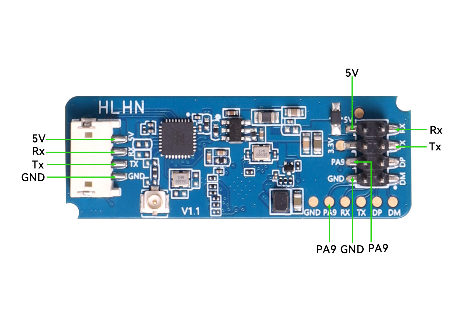 Figure 2-1 Module Pin Diagram
| Pin Name | Function |
|---|---|
| 5V | Power supply input 5V |
| GND | Power ground |
| Tx | Serial port Tx pin |
| Rx | Serial port Rx pin |
| PA9 | IO port (high level when someone is present, low level when no one is present) |
2.2 Installation Instructions
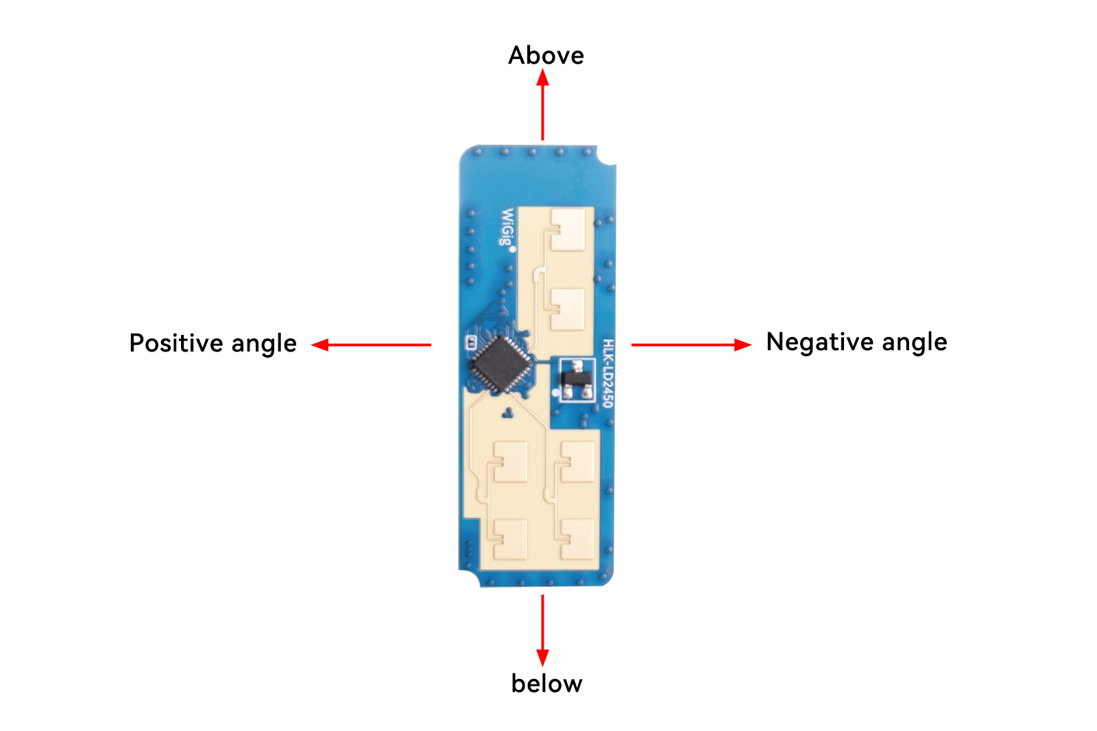
The typical installation method of the LD2450 is wall-mounted installation, as shown in Figure 2-2. The maximum positioning and tracking distance is 6 m. For wall-mounted installation, occlusion in the application scenario and interference objects at the top need to be considered. The recommended installation height range is 1.5–2 m.
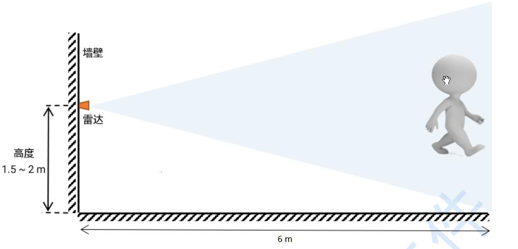
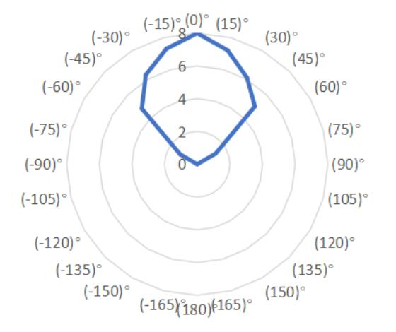
Figure 2-4 shows the positioning and tracking range of this module when the wall-mounted height is 1.5 m. The test subject is 1.75 m tall with a medium build. The detection angle range is ±60° centered on the normal direction of the radar antenna plane.
2.3 Usage Instructions
The LD2450 module directly outputs detection result data through the serial port according to the specified protocol. The serial port output data contains the position and speed information of up to three targets, and users can flexibly use it according to specific application scenarios. The module power supply voltage is 5V, and the input power supply capability must be greater than 200 mA. The module IO output level is 3.3V, and the output level pin is PA9. The serial port default baud rate is 256000, 1 stop bit, no parity bit.
2.4 Visual PC Tool Instructions
We provide a visual PC demonstration software for the LD2450, making it convenient for users to intuitively experience the positioning and tracking effect of the radar module on targets.
PC Tool Usage Method:
- Use a USB-to-serial tool to correctly connect the module serial port. For module pin description, please refer to Table 2-1 Pin Definition Table.
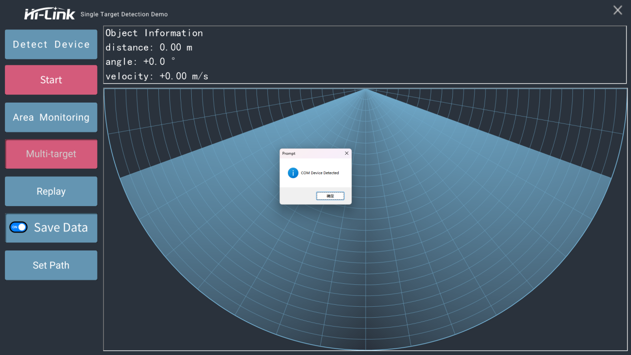
- Open the HLK-2450_TOOL.exe PC tool software and click the "Detect Device" button. The PC software will automatically search for the LD2450 module through the serial port. After the module is detected, the PC software will display a prompt as shown in the figure below.
- Then click the "Start" button. The PC software will receive the detection data reported by the LD2450 module and display it in real time on the software interface.
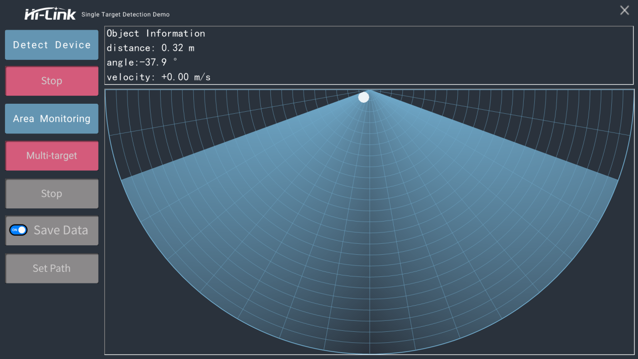 Display contents include: the real-time positions of up to three targets on the sector chart, and the distance, angle, and speed information of each target.
2.4 Mobile App Usage
(1) LD2450 App Download Address
https://www.hlktech.com/Mobile/App/12.html
(2) After downloading the app, you can search for the device. After connecting and entering, you can see the parameter setting page and its detection page. If you cannot enter the following pages, you can update the app to the latest version, and then upgrade the LD2450 to the latest firmware.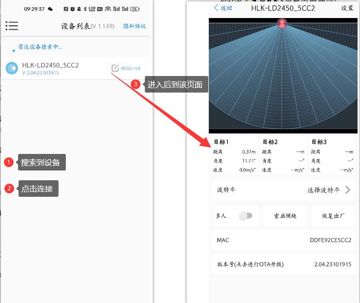
(3) If you need to learn more, please go to the resource module product manual below.
III. Precautions
- Try to ensure that the radar antenna faces the area to be detected, and that the surroundings of the antenna are open and unobstructed.
- Ensure that the sensor installation position is firm and stable. Shaking of the radar itself will affect detection performance.
- Ensure that there are no moving or vibrating objects behind the radar. Since radar waves are penetrating, the back lobe of the antenna signal may detect moving objects behind the radar. A metal shield or metal backplate can be used to shield the radar back lobe and reduce the impact caused by objects behind the radar.
- When multiple 24GHz band radars are present, do not install them facing each other's beam direction. Keep installation positions as far apart as possible to avoid possible mutual interference.