
 I. Introduction
1.1 Product Overview
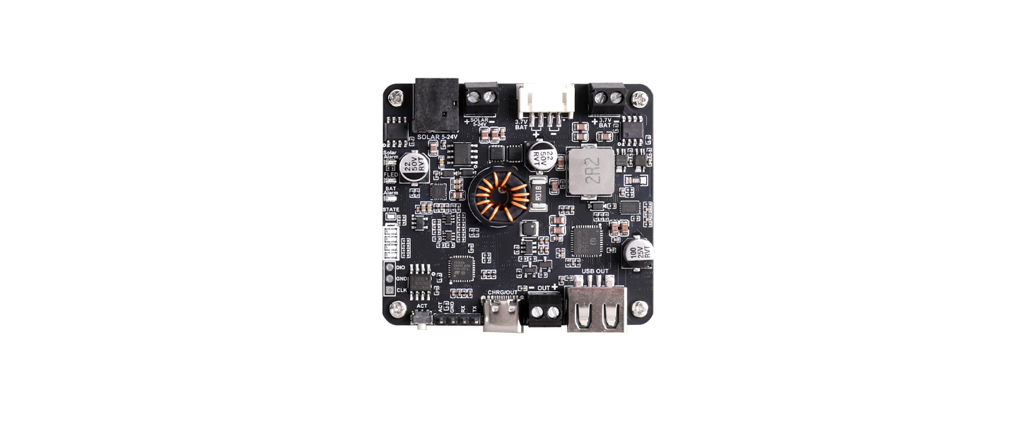
Solar Energy Manager F is a multifunctional power management module designed for solar-powered, portable energy storage, and embedded device applications. The module uses CN3881 as the solar charging management core, supports MPPT maximum power point tracking, and performs step-down charging for single-cell Li-ion/Li-polymer batteries.
An onboard STM32 MCU manages the system and enables automatic MPPT voltage adjustment without DIP switch settings.
The module also integrates the IP5356M fast-charging power management IC, providing USB Type-C bidirectional charging/discharging, USB-A output, and 3.5 mm terminal block output. It supports USB PD, QC, FCP, AFC, and other fast-charging protocols. The IP5356M itself supports up to 22.5 W boost output, with USB-C PD supporting 5 V, 9 V, and 12 V voltage levels.
On the battery side, the CW2217 fuel gauge IC measures battery voltage, current, and SOC in real time. An AT24C32 external EEPROM is provided to save system configuration, calibration parameters, or operating data. In addition, the module includes single-cell lithium battery protection circuitry, providing overcharge, over-discharge, overcurrent, and short-circuit protection.
This module is suitable for solar-powered terminals, portable energy storage, outdoor electronic devices, IoT nodes, backup power, and solar USB charging devices.
1.2 Product Features
- Approx. 20 W solar charging power with high conversion efficiency
- Supports automatic MPPT power point adjustment; no user setup required
- Supports multiple charging methods: solar panel / power adapter / USB
- Suitable for solar panels with output voltage of 5–24 V; connect via DC-044 power jack or terminal block
- More accurate battery monitoring using the CW2217 fuel gauge; monitors battery voltage, charge/discharge current, and SOC
- Onboard 3.5 mm terminal block, USB-A, and USB-C output interfaces; the Type-C port supports fast-charging output
- Onboard 3.5 mm terminal block and PH2.0-4P battery connector for easy connection to various 3.7 V rechargeable lithium batteries or battery packs
- Multiple onboard status LEDs for checking battery charge/discharge status and remaining battery capacity
- Supports battery capacity learning and setting; corrects the effective battery capacity based on actual charge/discharge processes
- Onboard overcharge/over-discharge/reverse-connection/overcurrent protection circuits for stable and safe operation
1.3 Product Specifications
| Parameter | Specification |
|---|---|
| Solar Panel Input Voltage | 5–24 V |
| Maximum Solar Charging Power | Approx. 20 W |
| USB Type-C Input/Output Voltage | 5 V / 9 V / 12 V |
| USB-A or Terminal Block Output | 5 V / 3.1 A |
| Charge Cutoff Protection Voltage | 4.2 V ±1% |
| Over-discharge Protection Voltage | 3.0 V ±1% |
| Battery Charging Efficiency | Solar: max. approx. 92%; USB: max. approx. 93% |
| Battery Boost Output Efficiency | Approx. 92% |
| Maximum Quiescent Current (Non-charging/Discharging) | Approx. 15 mA |
| Sleep Current (Sleep Mode) | Approx. 2 mA |
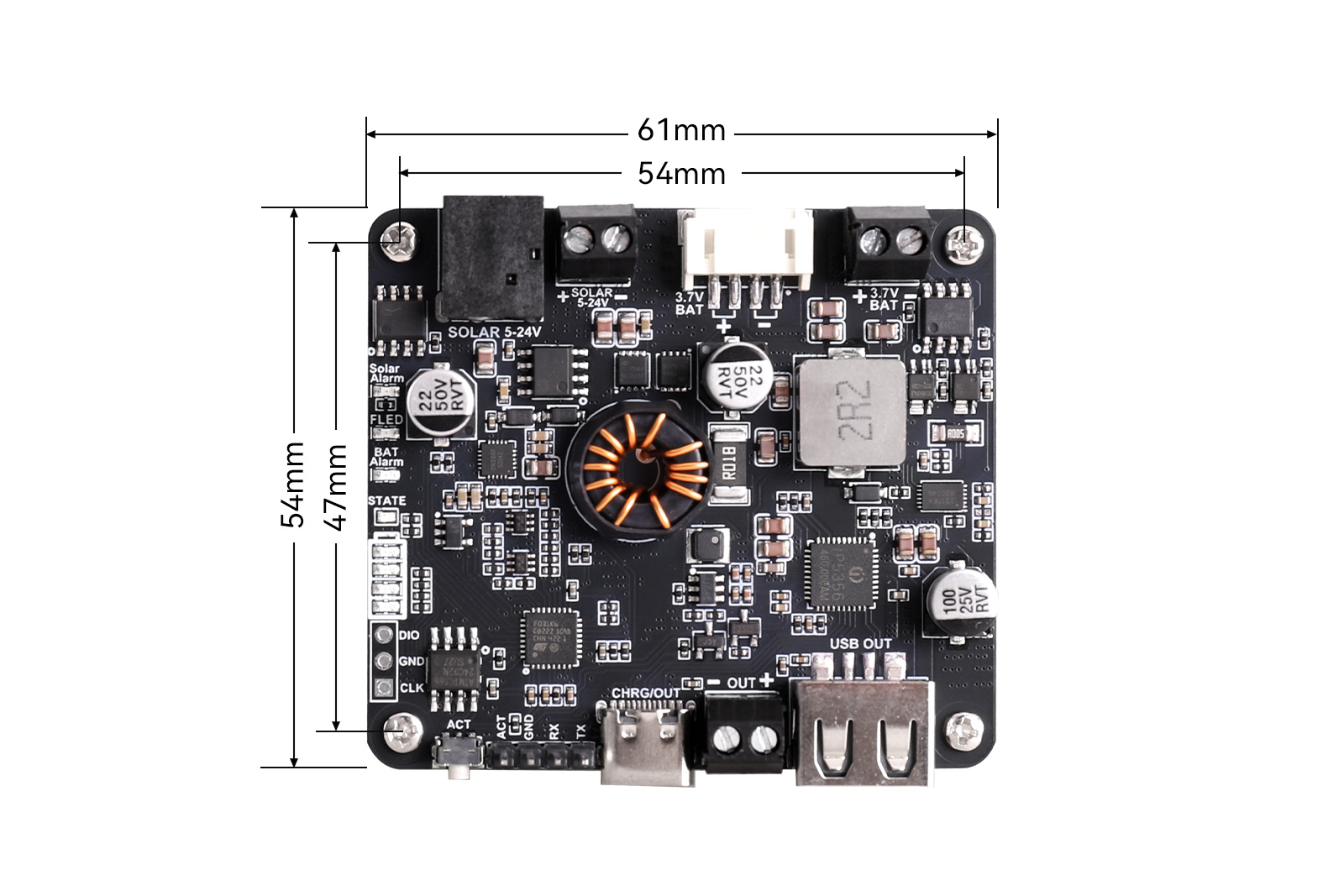
| Dimensions | 61 mm (L) × 54 mm (W) |
II.Usage
2.1 Resource Overview
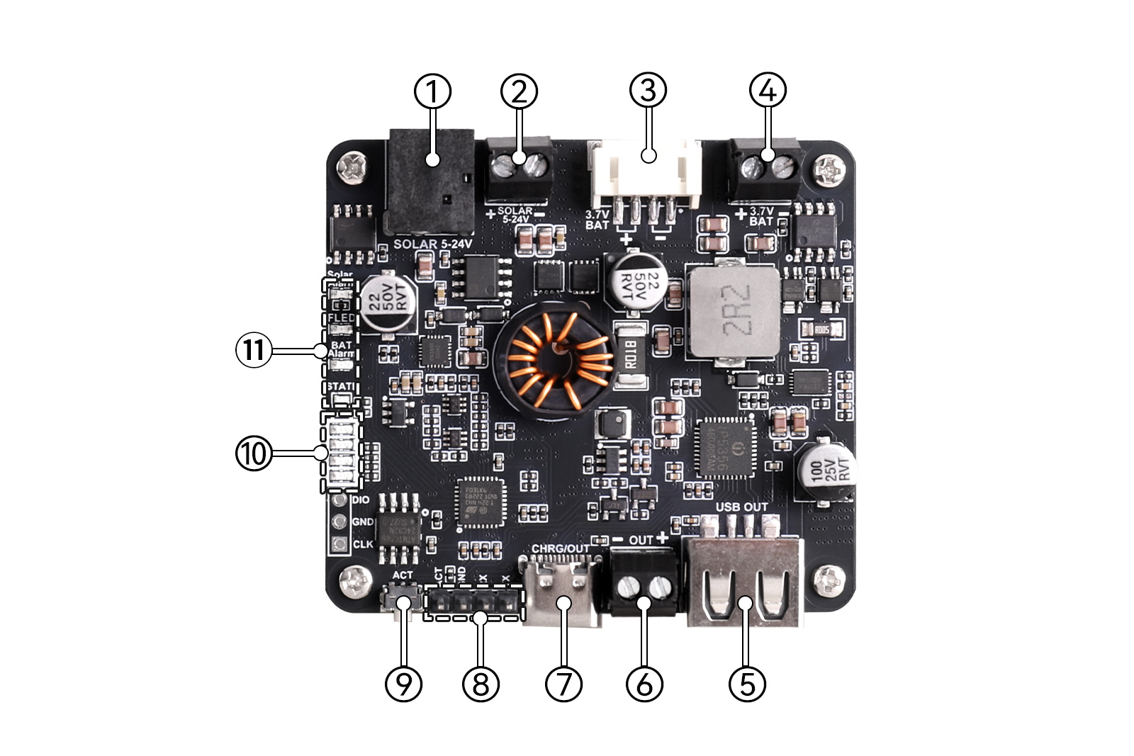
Figure 2-1 Solar Energy Manager F Resource Overview
① DC-044 Solar Charging Jack: Connect a solar panel through this power jack.
② 3.5 mm Solar Charging Terminal: Connect a solar panel through this terminal block.
③ PH2.0-4P Battery Input Connector: Connect a 3.7 V rechargeable lithium battery through this connector.
④ 3.5 mm Battery Input Terminal: Connect a 3.7 V rechargeable lithium battery through this terminal block.
⑤ USB-A Output Connector: Discharge to an external load through this connector.
⑥ 3.5 mm Output Terminal: Output up to 5 V/3.1 A to an external device through this terminal block.
⑦ USB-C Charge/Discharge Connector: Charge the battery or discharge through a Type-C cable; supports PD/QC/FCP/PE/SFCP and other protocols.
⑧ Debug Header Pads: TX and RX pins are STM32 UART pins. Through these pins, status information can be exchanged with the system. The ACT pin is connected to the ACT button.
⑨ Output Activation Button: If the board enters lockout due to low battery voltage, press this button to activate output. In working state, short press to put the system into sleep mode; long press for 8 seconds to enter battery capacity learning mode.
⑩ Battery Capacity Indicator: Displays battery capacity obtained by the system. Levels are 1–25%, 26–50%, 51–75%, and 76–100%. When battery capacity is 1–25%, the bottom LED lights and the others are off; at 26–50%, the bottom two LEDs light; and so on.
⑪ System Status Indicators:
- Solar Alarm: Solar input polarity reverse indicator
- FLED: Fast charging indicator
- BAT Alarm: Battery polarity reverse indicator
- STATE: IP5356M chip status indicator
2.2 Interface Description
Two solar panel input interfaces (see ① and ② in Figure 2-1): One DC-044 power jack and one KF128L-3.5-2P terminal block. Choose one according to the solar panel output interface. Do not connect a solar panel or power supply to both interfaces at the same time.
One USB Type-C input/output port (see ⑦ in Figure 2-1): You can charge the battery through the USB Type-C connector and also discharge through this port. When USB Type-C is selected to charge the battery, the board will actively disconnect solar panel charging. When the connected device supports fast charging protocols, the FLED LED lights up.
Two battery connectors (see ③ and ④ in Figure 2-1): The user can choose either one (3.5 mm terminal block or PH2.0-4P connector) to connect a 3.7 V lithium battery. Pay attention to battery polarity when connecting; do not reverse the battery positive and negative terminals. The module has battery reverse-connection protection and alarm. After installing the battery, if the BAT Alarm LED stays on, it indicates the battery polarity is reversed; immediately reinstall the battery correctly.
One activation button (see ⑨ in Figure 2-1): When battery voltage is lower than 3 V, the board enters lockout state to protect the battery. In lockout state, the board cannot discharge normally. It must enter charging state (solar charging or Type-C port charging) or press the activation button to activate discharge.
During discharge with a load, the larger the load current, the higher the battery rebound voltage after low-voltage lockout is triggered; the smaller the load current, the lower the rebound voltage. This is because the battery has internal resistance. When a load is connected, battery current flows through the internal resistance, causing a voltage drop inside the battery. The voltage drop depends on current; therefore, a larger load current causes a more obvious voltage drop, lowering the battery terminal voltage. When the load is removed, the internal voltage drop disappears and the battery voltage rebounds to normal.
In idle state with no charging/discharging, short press this button to put the system into sleep mode to save quiescent power. In sleep mode, the system pauses monitoring of operating parameters. Short press again to wake up from sleep.
2.3 Product Usage
Note:
Pay attention to polarity when installing the battery and connecting the solar panel; do not reverse connections. Do not directly touch core components with both hands during operation; take ESD precautions. When supplying power to a load through the header pins, pay attention to polarity; do not reverse connections.
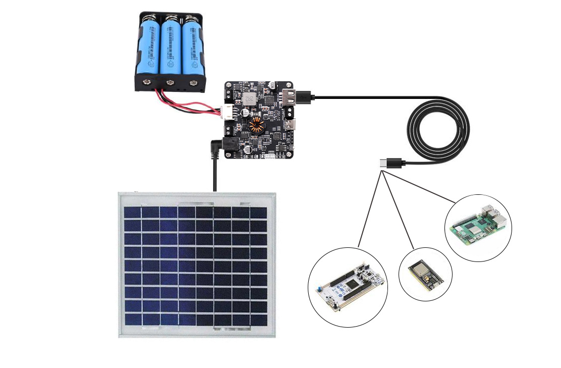 Figure 2-2 Wiring Diagram
2.4 Related Notes
Battery capacity: When battery capacity changes due to battery replacement, adding, or removing batteries, it is recommended to reset the system battery capacity. The default battery capacity is 7600 mAh. There are two methods to reset battery capacity:
Method 1: A host computer or MCU can connect to the RX pin of the UART interface (see ⑧ in Figure 2-1) and send a battery capacity setting command to the onboard STM32. The battery capacity value takes effect immediately after setting. For command format and content, see the Serial Communication User Manual.
Method 2: Long press the activation button (see ⑨ in Figure 2-1) for 10 seconds to make the system enter battery capacity learning mode. The battery capacity learning process requires first fully charging the battery and then discharging it to the low-voltage protection state. During the discharge phase of capacity learning, it is not recommended to use too large a discharge current; otherwise, large-current discharge will cause the system to learn a smaller battery capacity due to the battery's internal resistance. A discharge current of 100 mA–500 mA is generally recommended.
After long pressing the button for 10 seconds, the battery capacity learning process is as follows:
Time Action Hold for about 8 s All four battery level LEDs flash simultaneously (indicating imminent clearing) Hold until 10 s The LEDs return to normal display state; EEPROM is cleared; C is set to default 7600; L=0, F=0; R/b estimated from current voltage → enter learning-to-be state After that: fully charge (F=1) → discharge to empty (approx. ≤3.0 V); only then is C updated according to the discharged capacity, completing this learning cycle.
Other conditions must also be met: voltage ≥3.2 V; current within approx. ±500 mA; not in low-voltage lockout; no solar input (when solar input is present, this long press will be ignored).
Note:
A. For the meanings of characters "C", "L", "F", "R", and "b" mentioned above, please refer to the Serial Communication User Manual.
B. If the discharge current is large, the battery voltage may reach 3.0 V relatively quickly due to battery internal resistance and trigger low-voltage protection. In this case, the actual capacity will be somewhat smaller than the capacity displayed by the system. This is normal.
About battery charging power: The lower the battery level, the greater the charging power; the higher the solar panel output power, the greater the charging power. When the solar panel output power is sufficient and the battery level is low, the maximum charging power is approximately 20 W.
The board supports simultaneous charging and discharging, i.e., discharging while solar charging or discharging while USB charging. In USB simultaneous charge/discharge mode, fast charging is not supported; both charge and discharge voltages are 5 V, and the maximum charging current is 2 A. In solar simultaneous charge/discharge mode, fast charging is supported.
During charging, once a load is connected to the board, its output will remain on. Even if the load is removed during this period, the STATE green LED will continue flashing until the charging power source is removed.
Onboard LED indicator definitions are shown in Table 2-2:
LED Indicator Description Solar Alarm (red) Lights up when solar charging input polarity is reversed. FLED (red) Lights up during fast charging. STATE (red/green dual-color) When charging only: flashes red at 1 Hz. When discharging only: steady red. During simultaneous charge/discharge: flashes green at 1 Hz (including discharging at USB full-charge state). No load and fully charged: steady green. Idle (no charging/discharging) and sleep: off. BAT Alarm (red) Lights up when battery polarity is reversed. Battery Level (see Figure 2-1: 4 red LEDs) Indicates battery level. More LEDs lit from bottom to top means higher battery level; fewer means lower. Off in sleep mode. The product's default function is that once a load is connected, the output remains on, and the battery level LEDs remain lit (provided the battery is sufficiently charged). Even if you remove the load during use, the board will not automatically enter sleep mode. At this time, you can press the output activation button (⑨ in Figure 2-1) once to make the module enter idle state first (the STATE LED will turn off first), then short press again to make the board enter sleep mode (the battery level LEDs will turn off). The board's sleep current is approximately 2 mA, so you can make the board's standby time very long.
Serial communication commands: See the attached document Serial Communication User Manual.