
 I. Introduction
1.1 Product Overview
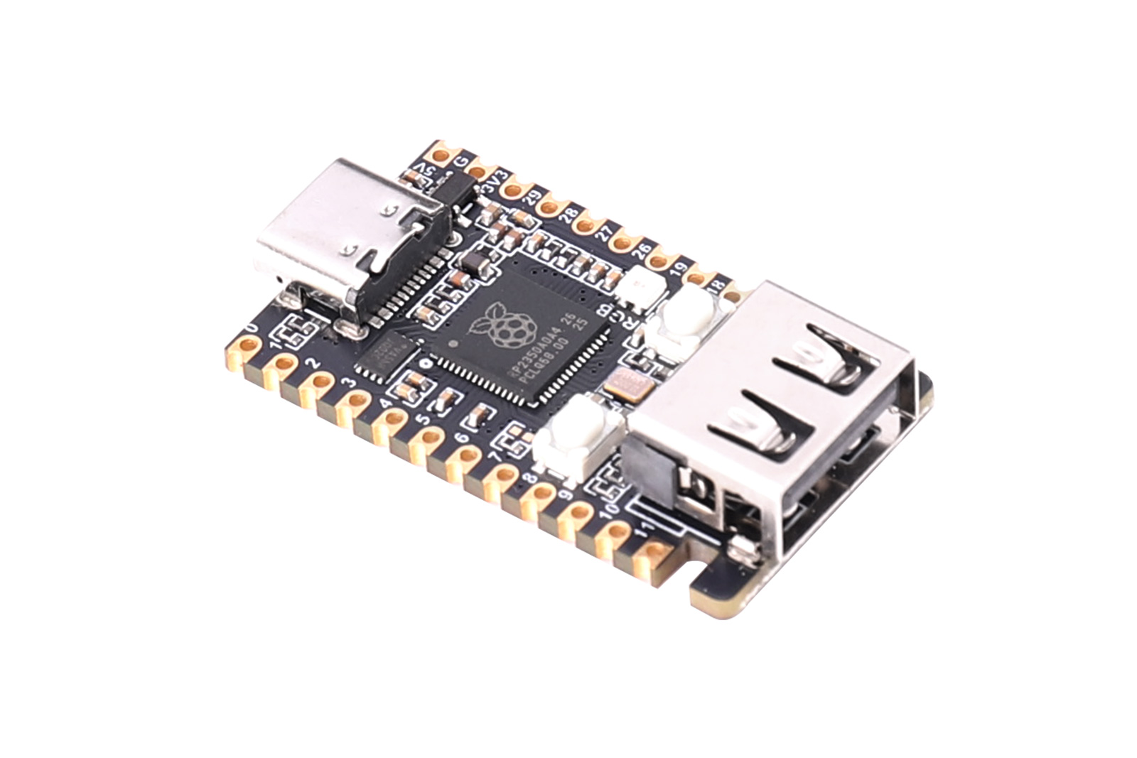
RP2350 USB MINI is a mini development board designed based on the RP2350A microcontroller. The onboard USB Type-C interface is used for 5V power supply, program download, and RP2350A native USB communication. It also adds a USB Type-A expansion port, which can implement USB expansion applications through GPIO12/GPIO13 with PIO (Programmable I/O). The board integrates BOOT and RUN buttons, a WS2812 full-color RGB LED, 4MB NOR Flash, and an SWD debug interface. Most GPIOs are led out through pin headers/solder pads, making it convenient for prototype verification and embedded integration.
RP2350A uses a dual-core, dual-architecture design and can run dual-core Arm Cortex-M33 or dual-core Hazard3 RISC-V processors, with a maximum operating frequency of 150MHz. The chip integrates 520KB SRAM, rich digital peripherals, 12 PIO state machines, and security-related hardware capabilities. RP2350A itself does not integrate user program Flash. This board provides 4MB external NOR Flash through W25Q32RVXHJQ.
This board is suitable for USB peripheral/host experiments, HID control, sensor and actuator control, teaching and development, embedded prototyping, portable tools, and applications requiring a compact RP2350 control core.
1.2 Product Features
- Uses RP2350A microcontroller, supports dual-core Arm Cortex-M33 or dual-core Hazard3 RISC-V architecture, up to 150MHz.
- Chip has built-in 520KB SRAM; onboard W25Q32RVXHJQ 4MB NOR Flash for program and data storage.
- USB Type-C interface connects to the RP2350A native USB controller, supports USB 1.1 full-speed/low-speed host or device functions, and can be used for UF2 drag-and-drop download.
- Onboard USB Type-A expansion port; GPIO12 as D+, GPIO13 as D-, can be combined with PIO USB software to implement USB expansion applications.
- The board provides 28 external GPIO signals, of which GPIO16 is shared with WS2812, and GPIO12/GPIO13 are dedicated to USB Type-A data lines.
- Onboard BOOT download button, RUN reset button, and WS2812 full-color RGB LED, convenient for download, debugging, and status indication.
- Supports common development environments such as C/C++ Pico SDK, MicroPython, and Arduino-Pico, and is compatible with the Raspberry Pi Pico 2/RP2350 software ecosystem.
1.3 Product Specifications
Parameter | Specification |
|---|---|
| Main Controller | RP2350A |
| Power Input | 5V (via USB-C connector or 5V pin) |
| Processor | Dual-core Arm Cortex-M33 or dual-core Hazard3 RISC-V, up to 150MHz |
| Memory | 520KB on-chip SRAM and 4MB external NOR Flash (W25Q32RVXHJQ) |
| USB Type-C | 5V power; connects to RP2350A native USB D+/D-; supports UF2 download and USB host/device |
| USB Type-A | PIO USB expansion port; GPIO12 = D+, GPIO13 = D-; 5V VBUS comes from VSYS |
| Common Digital Peripherals | 2× UART, 2× SPI, 2× I2C, PWM, 12× PIO state machines, etc. |
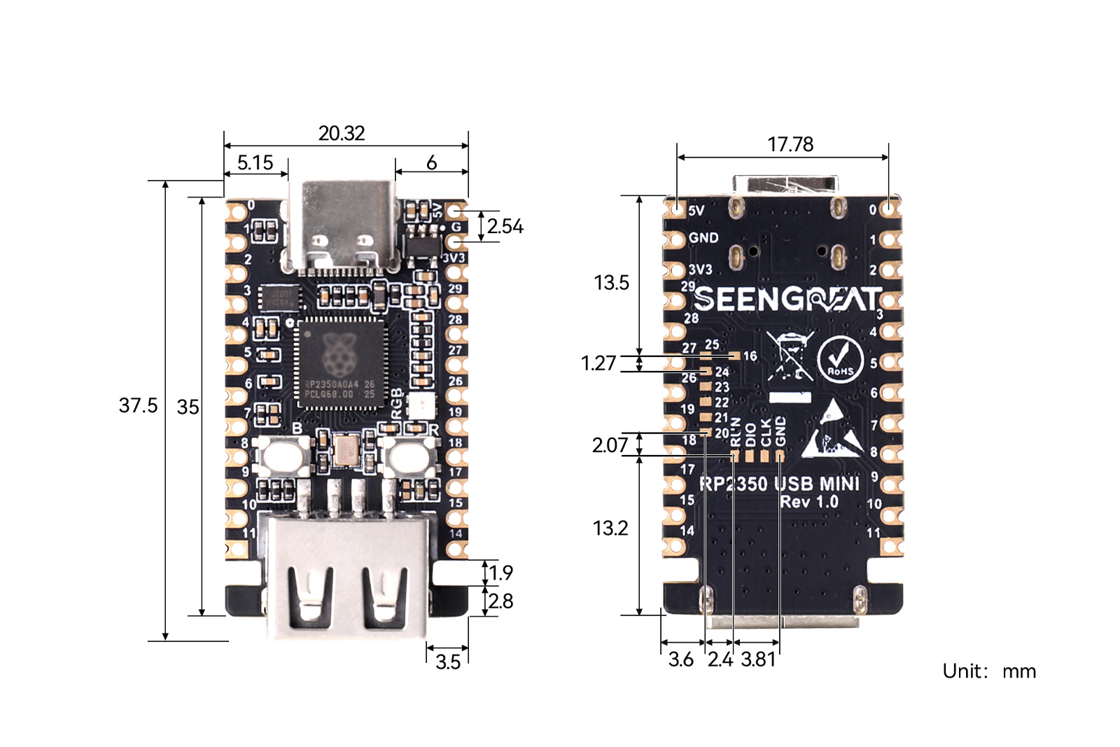
| Mechanical Dimensions | 37.5mm (L) × 20.32mm (W) |
II.Usage
2.1 Resource Overview
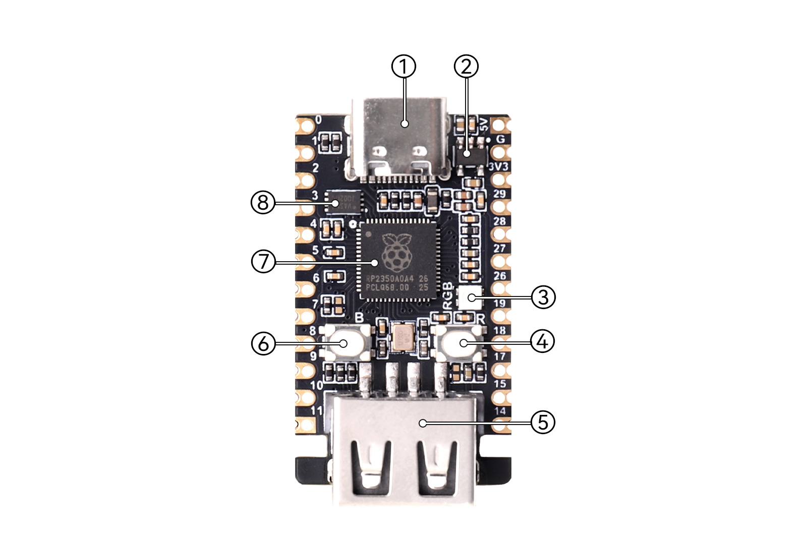
Figure 2-1 RP2350 USB MINI Resource Overview
① Type-C connector: supports USB 1.1 host and device, can be used for program download
② Linear regulator ME6211C33M5G③ WS2812: full-color RGB LED
④ RUN reset button
⑤ USB Type-A female connector
⑥ BOOT button: press and hold this button, then power on to enter download mode
⑦ RP2350A: dual-core Arm Cortex-M33 or dual-core Hazard3 RISC-V processor @150MHz
⑧ W25Q32RVXHJQ: 4MB NOR Flash
2.2 GPIO Pinout
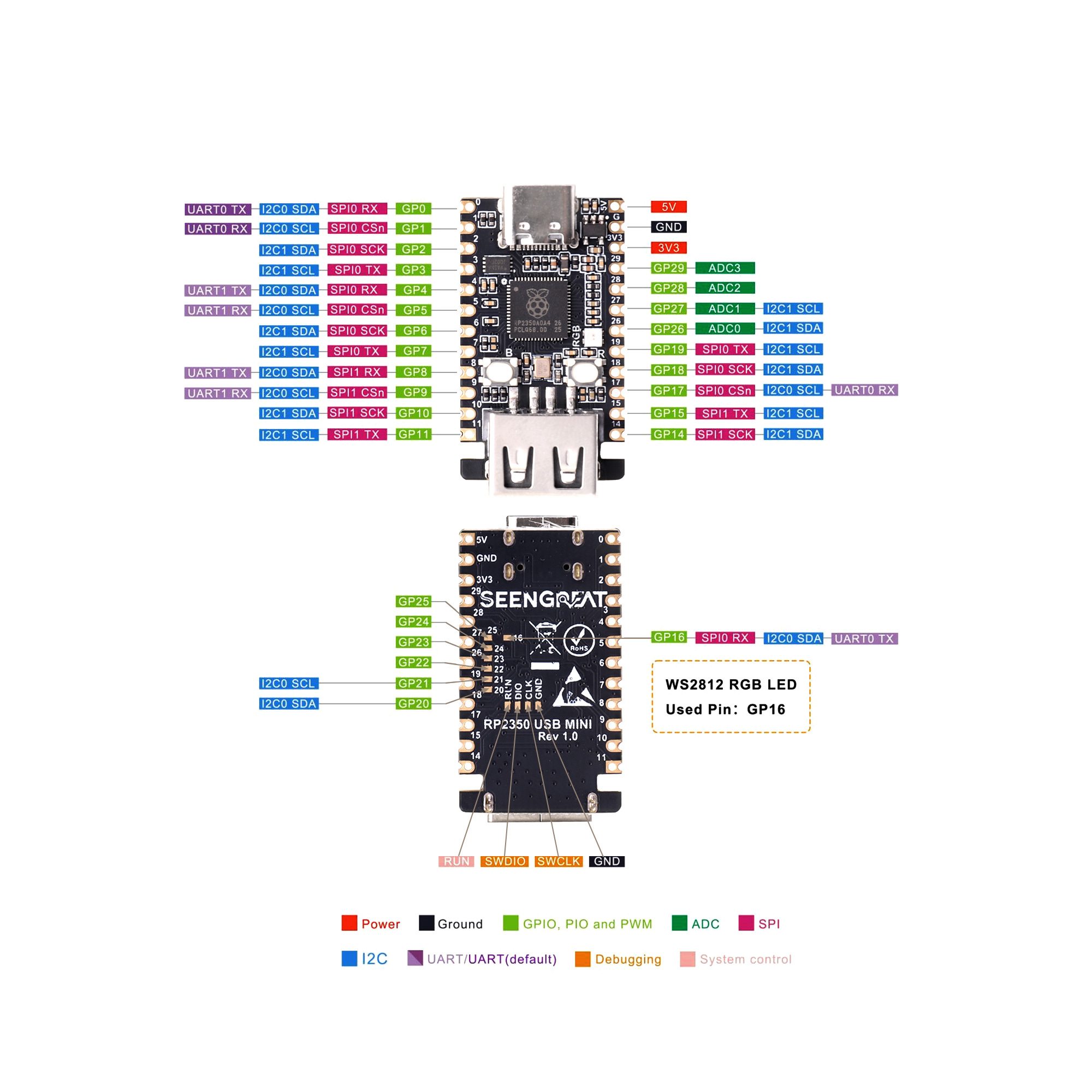
Figure 2-2 GPIO Pinout
2.3 python demo code usage
- Install ThonnyThonny download URL: https://thonny.org
- After installing Thonny, with the board powered off, press and hold the BOOT button on the RP2350-MINI (⑤ in Figure 2-1). Connect it to the computer with a USB cable, then release the button. An RP2350 disk drive will appear on the computer. Drag
RPI_PICO2-20241025-v1.24.0.uf2from thedemo codesdirectory into the RP2350 disk. - Right-click
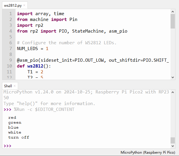
ws2812.pyin thedemo codesdirectory and open it with Thonny. Click Tools > Options > Interpreter. In the interpreter field, select MicroPython (Raspberry Pi Pico), set the port (COMx; the port number may vary by computer), and click OK. - Click "Run current script" or press F5 to run the current script and observe the WS2812 display.
2.4 C/C++ Environment
For C/C++, Pico VS Code is recommended for development. You can refer to the official Raspberry Pi tutorial:https://www.raspberrypi.com/news/pico-vscode-
2.5 Arduino
1. Install Arduino IDE
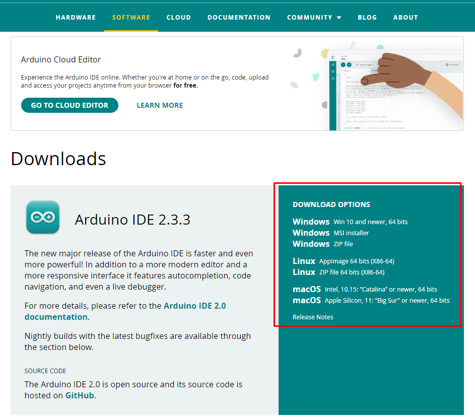
Download the Arduino IDE installer from the official Arduino website:https://www.arduino.cc/en/software
As shown in the lower-right red box in Figure 2-4, click to download the appropriate installer for your computer OS.
On the page that appears, select "JUST DOWNLOAD."
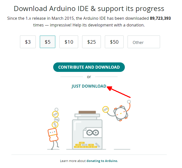
Figure 2-5
After the installer is downloaded, install it. If prompted to install drivers during installation, click Install.
2. Configure Pico Environment in Arduino IDE
Open Arduino IDE, select File > Preferences, then click the lower-right corner of the pop-up window (shown by the red arrow in Figure 2-6).
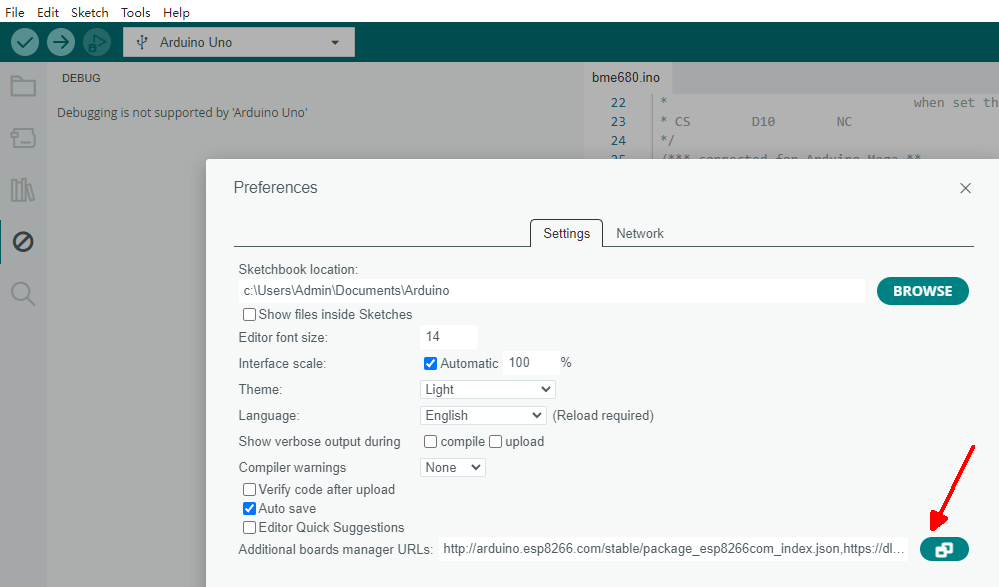
Figure 2-6
In the pop-up window, add:
https://github.com/earlephilhower/arduino-pico/releases/download/global/package_rp2040_index.jsonas shown in the red box in Figure 2-7.
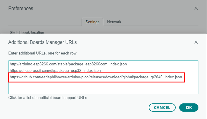
Figure 2-7
Click Tools > Board: > Boards Manager..., enter "pico", and in the results find the content shown in the red box in Figure 2-8, then click "INSTALL" and wait for installation to complete.
If installation fails, you can also download the RP2040 ZIP package, extract the rp2040 folder, and copy it to:
\Users\[username]\AppData\Local\Arduino15\packages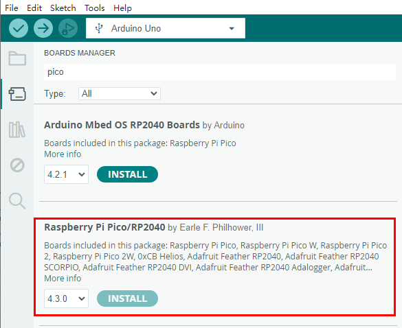
Figure 2-8
where [username] is your computer username.
3. First Program Download
With the board powered off, press and hold the BOOT button on the RP2350-MINI (⑤ in Figure 2-1), connect it to the computer with a USB cable, then release the button. An RP2350 disk drive will appear.
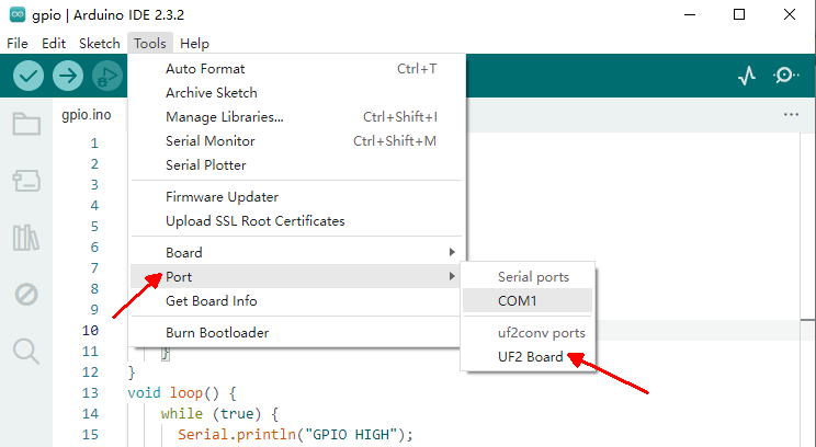
After downloading the demo codes, double-click to open \Arduino\gpio\gpio.ino, then click Tools > Port > UF2 Board, as shown in Figure 2-9.
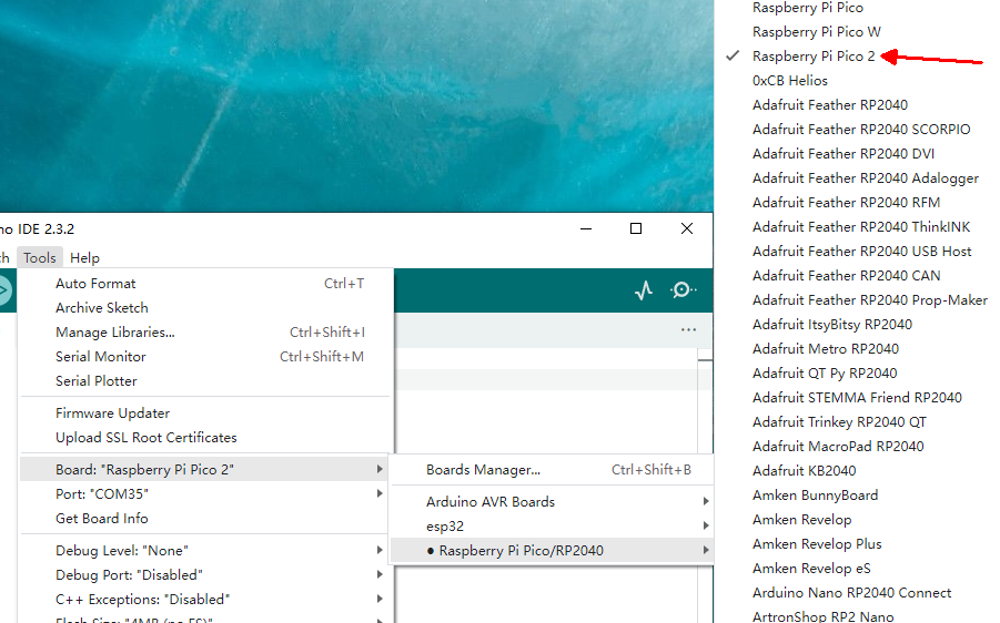
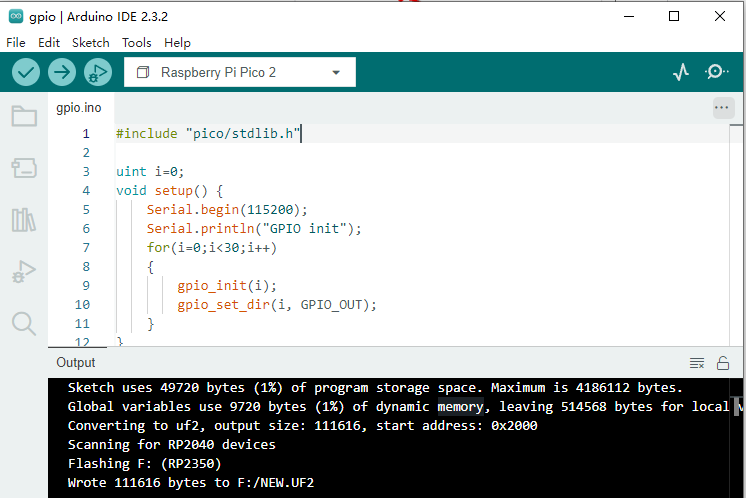
Click Tools > Board > Raspberry Pi Pico/RP2040 > Raspberry Pi Pico 2, as shown in Figure 2-10, then click "Upload." After upload is complete, see Figure 2-11.
4. Run the Example
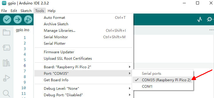
Select Tools > Port > COM35 (Raspberry Pi Pico), as shown in Figure 2-12. The port number may differ for different boards. If the port is not detected, try power-cycling the RP2350-MINI.
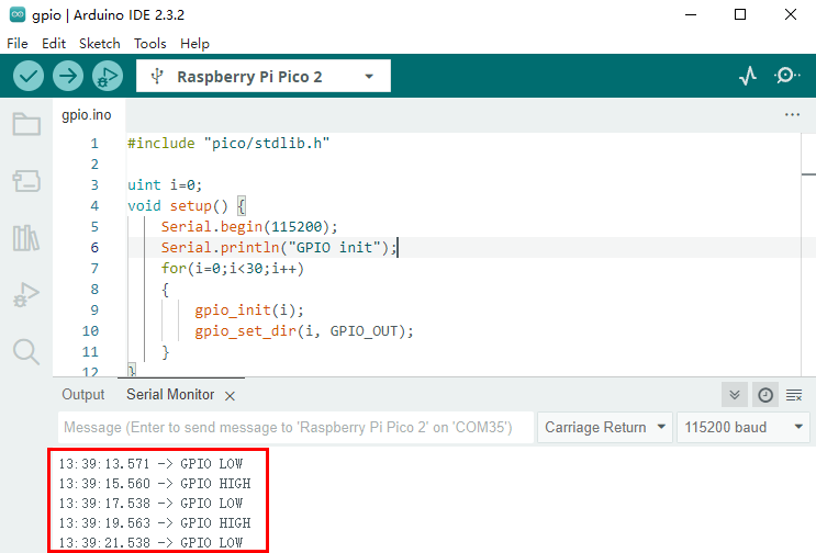
Click "Upload" to upload the program. After upload completes, click Tools > Serial Monitor to open the serial monitor. It will output GPIO high/low level information, as shown in Figure 2-13. All GPIO pins led out on the board will also toggle every 2 seconds.
2.6 USB Device Example Code
Please refer to the link:https://seengreat.com/wiki/221/
III. Resources
3.1 Schematic
3.2 demo codes
3.3 Official Resources
- Pico 2 Getting Started Guide
- Pico 2 C SDK Guide
- Pico 2 Python SDK Guide
- Pico 2 Schematic
- Pico 2 Datasheet
- Pico 2 Hardware Design Reference
- Raspberry Pi Official C/C++ Examples (GitHub)https://github.com/raspberrypi/pico-examples/
- Raspberry Pi Official MicroPython Examples (GitHub)https://github.com/raspberrypi/pico-micropython-examples
- Arduino Official C/C++ Examples (GitHub)https://github.com/earlephilhower/arduino-pico