
1. ESP-IDF v5.5.5 Environment Setup and Web Testing
1.1 Open the Official Download Page and Download the Installer
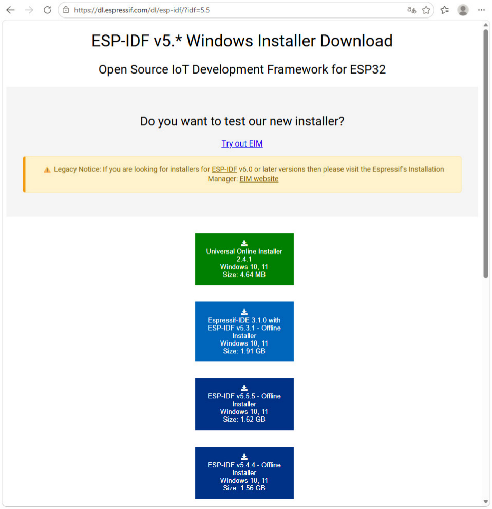
Open a browser and visit Espressif's official ESP-IDF Windows installer download page:
https://dl.espressif.com/dl/esp-idf/?idf=5.5
Find and click ESP-IDF v5.5.5 - Offline Installer (Windows 10/11) to download the installation package.
1.2 Start the Installer and Select a Language
After the download is complete, double-click the installer. Select English in the language window, and
then click OK.
1.3 Select the Installation Directory
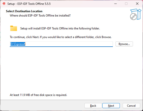
Set the installation directory on the Select Destination Location page. This guide uses:
D:\Espressif
Select a drive with sufficient free space, and avoid Chinese characters and spaces in the path. Click
Next when finished.
1.4. Confirm the Installation Configuration
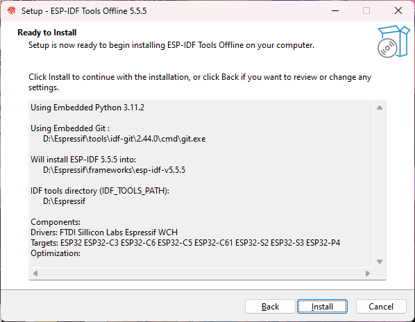
On the Ready to Install page, verify the ESP-IDF version, installation directory, Python, Git, drivers,
target chips, and other information. Click Install after confirming the settings.
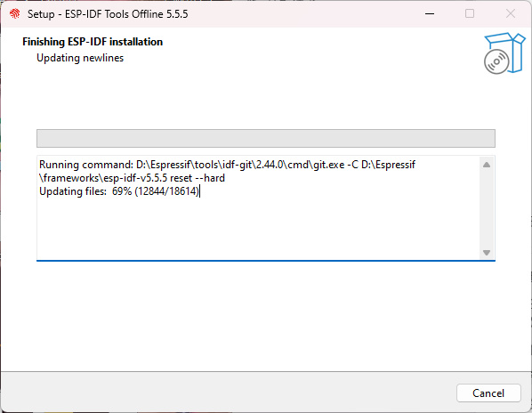
1.5. Wait for the Installation to Complete
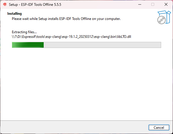
The installer automatically extracts and configures ESP-IDF, Python, Git, the compiler toolchain, and
related drivers. Wait for the process to finish, and do not close the installer.
1.6. Complete the Installation
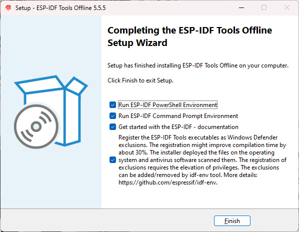
When the Completing the ESP-IDF Tools Offline Setup Wizard page appears, the installation is
complete. Keep the required options selected, and click Finish.
If both ESP-IDF PowerShell and ESP-IDF Command Prompt are selected, two terminal windows will
open after installation.
1.7. Verify the ESP-IDF Environment
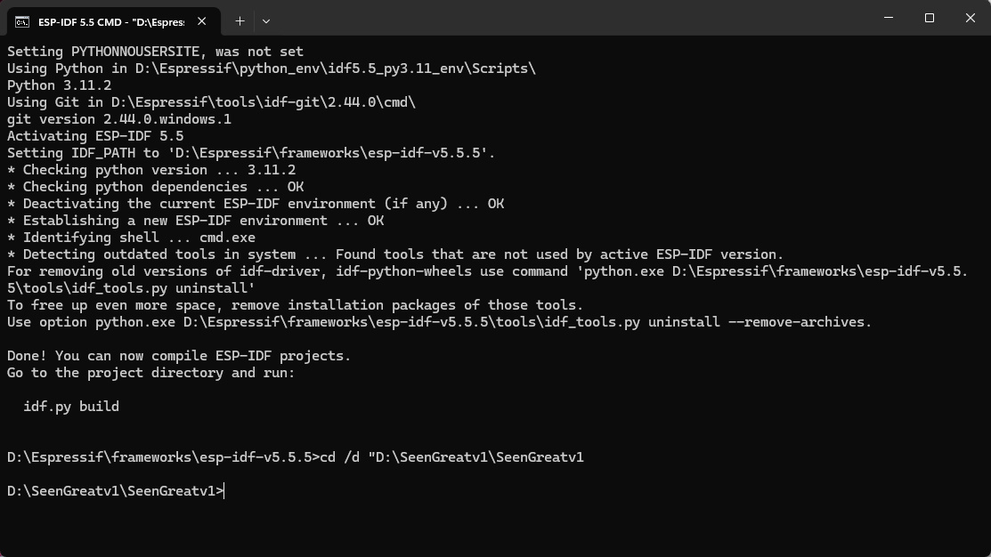
After installation, ESP-IDF 5.5 PowerShell and ESP-IDF 5.5 CMD will open. The following message
indicates that the environment has loaded successfully:
Done! You can now compile ESP-IDF projects.
The two terminals provide essentially the same functions, so only one is needed. This guide uses ESP-
IDF 5.5 CMD. It is normal for the terminal to open in the installation directory by default.
1.8. Configure Wi-Fi
Open the main\core\main.c file in the project.
Find and modify the Wi-Fi network name and password:
#define WIFI_SSID "YourNetworkName"
#define WIFI_PASSWORD "YourPassword"
Enter the details of the 2.4 GHz Wi-Fi network or mobile hotspot, and save the file. The Wi-Fi name
and password are case-sensitive.
1.9. Enter the Project Directory
Open ESP-IDF 5.5 CMD and enter the following command to access the project root directory:
cd /d "D:\SeenGreatv1\SeenGreatv1
When the prompt changes to D:\SeenGreatv1\SeenGreatv1>, the directory has been changed
successfully. Adjust the path according to the actual project location.
1.10. Set the Target Chip
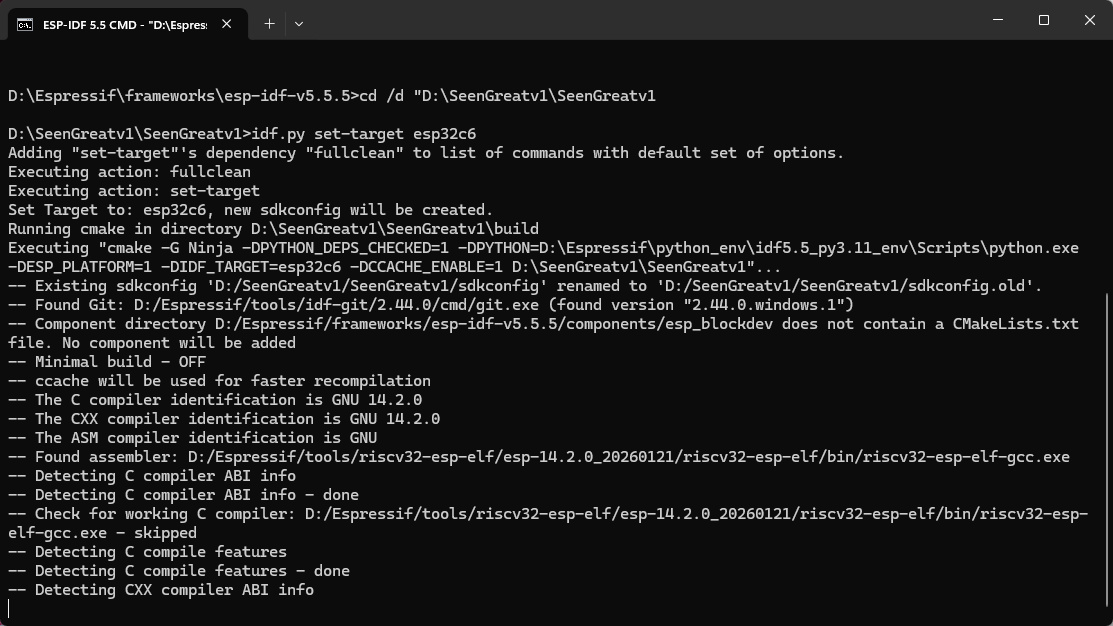
Run the following command in the project root directory:
idf.py set-target esp32c6
After Set Target to: esp32c6 appears, wait for the command to finish and for the project directory
prompt to return.
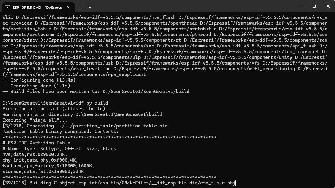
1.11. Build the Project
Run the following command in the project root directory:
idf.py build
The first build compiles many files. Wait for it to finish, and do not close the terminal.
Project build complete indicates that the build was successful.
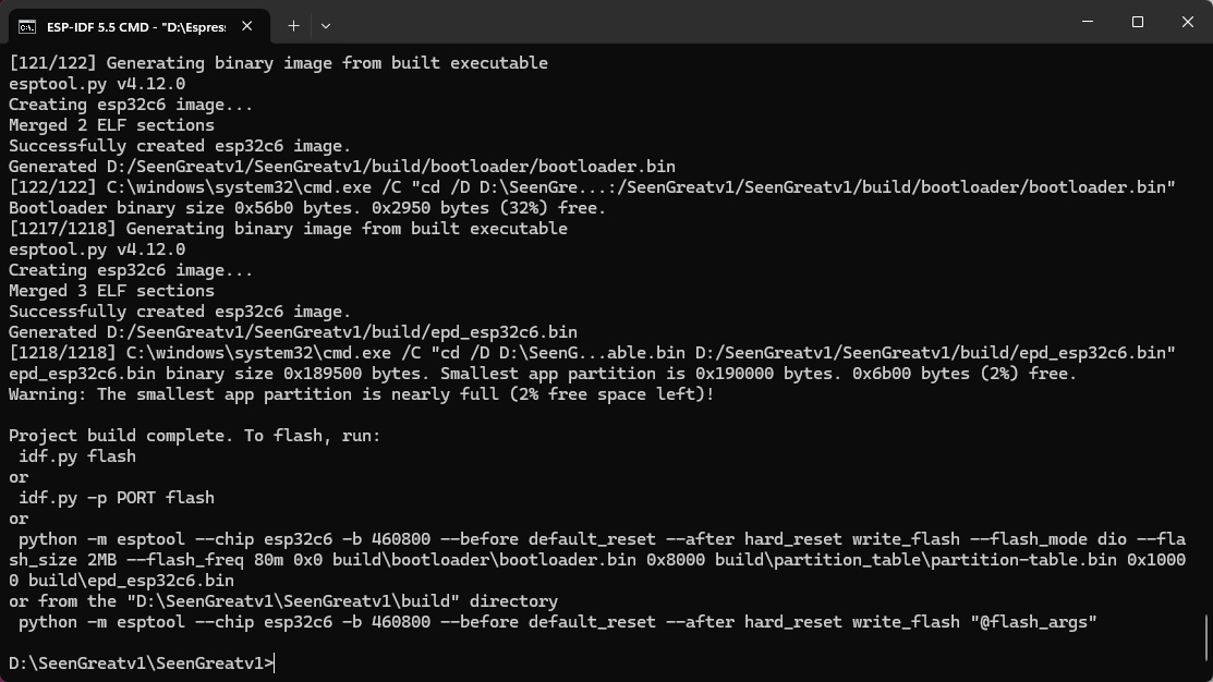
Note: If a path-length error occurs, copy the project to a shorter path and rebuild it, for example,
D:\SeenGreatv1\SeenGreatv1.
1.12. Connect the Board and Flash the Firmware
With the power disconnected, connect the e-paper FPC cable. Confirm that S1 is ON (4-wire SPI), and
set S2 according to the e-paper model. Connect the board using a USB Type-C cable that supports
data transfer.
Run the following command in the project root directory:
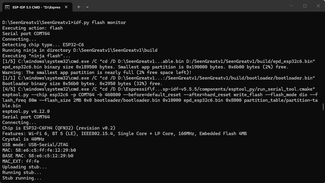
idf.py flash monitor
ESP-IDF automatically detects the serial port, identifies the ESP32-C6, flashes the firmware, and opens
the serial monitor. If multiple serial ports are available, specify the port:
idf.py -p COMx flash monitor
1.13. Confirm That the Program and Wi-Fi Are Working
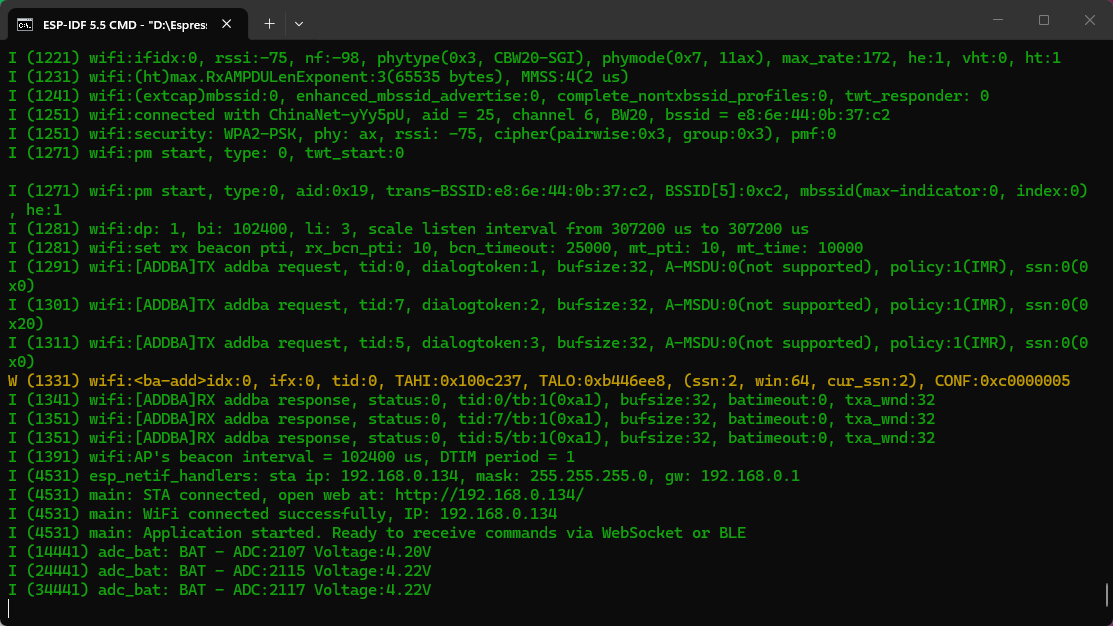
After flashing, check the serial log. The following messages indicate that the Wi-Fi, WebSocket, and
BLE services have started:
WiFi connected successfully, IP: 192.168.0.134
Application started. Ready to receive commands via WebSocket or BLE
The actual IP address is assigned automatically by the network. Use the address shown in the serial
log. Press Ctrl + ] to exit the serial monitor.
1.14. Open the Web Control Page
Connect the computer or phone to the same network as the ESP32-C6, and open the IP address shown
in the serial log in a browser, for example:
http://192.168.0.134/
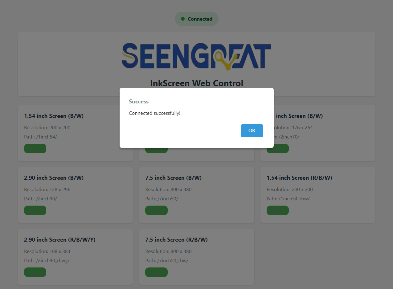
Connected appears at the top of the page and a Connected successfully! message is displayed,
indicating that the browser is connected to the board. Click OK.
1.15. Select the Corresponding E-Paper Display
Select the option that exactly matches the connected e-paper display's size, resolution, and color type.
B/W indicates a black-and-white display; R/B/W indicates a red/black/white display; R/B/W/Y indicates
a red/black/white/yellow display.
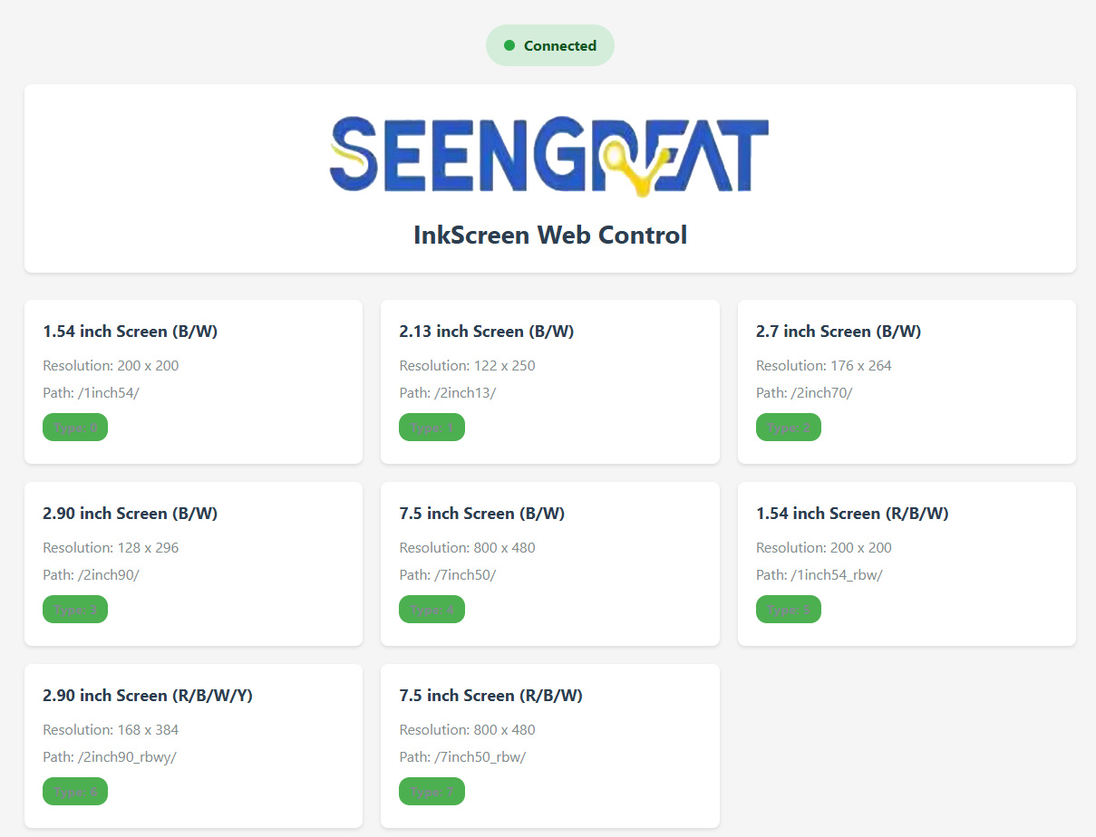
Note: Selecting the wrong model may result in an incorrect image size, refresh failure, or no display output.
1.16. Confirm the E-Paper Model
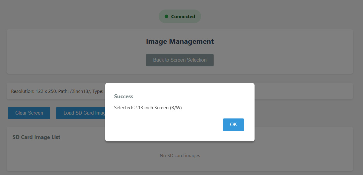
After selection, the page opens Image Management and displays the selected model. Confirm that it
matches the actual display, and click OK.
If the wrong model was selected, click Back to Screen Selection and select again.
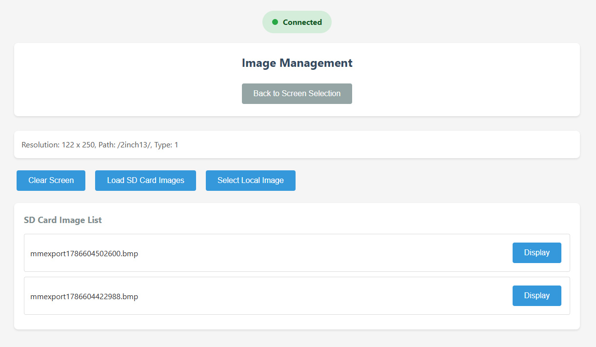
1.17. Load and Display an SD Card Image
Before use, format the Micro SD card as FAT32 (formatting erases all data, so back up the card first),
and insert it into the board. Click Select Local Image and confirm that the image matches the actual
display model.
Click Upload & Display. The image will be displayed and automatically uploaded to the corresponding
SD card subfolder.
Click Read SD to load the image list from the SD card.
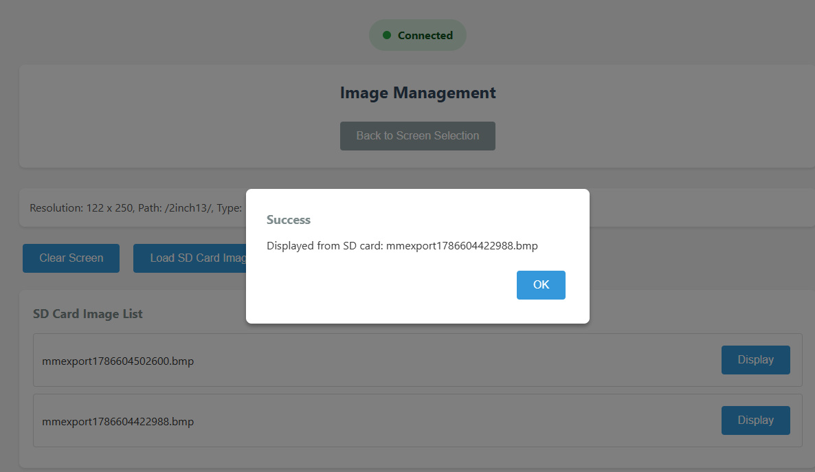
Click Load SD Card Images to load the image list, and then click Display beside the target image.
1.18. Confirm That the Image Was Displayed Successfully
The Displayed from SD card message indicates that the board has read the image and sent the display
command to the e-paper. Click OK and check the actual display result.
The ESP-IDF environment, firmware build and flashing, Wi-Fi, WebSocket, SD card reading, and e-
paper refresh functions have now all been tested.
2. APP User Guide (Wi-Fi / Bluetooth)
2.1 Preparation:
The firmware has been flashed to the board and the board is connected to Wi-Fi.
For Wi-Fi operation, connect the phone and board to the same Wi-Fi network or mobile hotspot.
Use a Micro SD card formatted as FAT32.
For Android Phones Only
2.2 Download and Install the APP
Download the Android APP installation package (APK) from the product resources.
Open the APK file on the Android phone and complete the installation.
If the system blocks installation from unknown sources, follow the prompt to allow this installation.
After installation, open SEENGREAT Ink Display Console
2.3 View the Board IP Address
Connect the board to the computer with a USB data cable, and open a serial debugging tool.Select the serial port corresponding to the board and open it with the following settings:
Baud rate: 115200
Data bits: 8
Stop bits: 1
Parity: NONE
Flow control: NONE
Press the BOOT button on the board and view the serial output.Find the IP address following WiFi connected successfully or open web at:
STA connected, open web at: http://192.168.0.134/
WiFi connected successfully, IP: 192.168.0.134
Note: 192.168.0.134 is only an example. Use the IP address shown in the actual serial log.
2.4. Connect to the Board (Wi-Fi or Bluetooth)
Confirm that the phone and board are connected to the same Wi-Fi network. The board may also connect to the phone's hotspot.
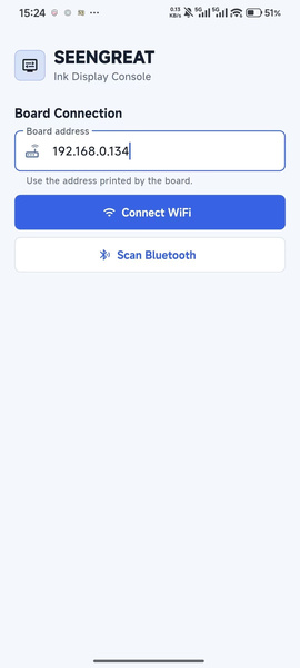
Open the APP and enter the board IP address shown in the serial log in Board address.
Tap Connect WiFi and wait for the APP to connect to the board.
Note: Enter only the IP address, such as 192.168.0.134. Do not include http:// or a trailing slash.
2.5 Bluetooth Connection
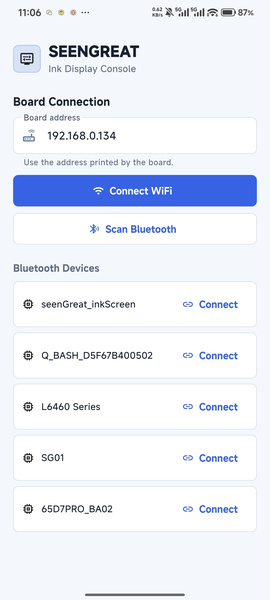
Enable Bluetooth on the phone. If the APP requests Bluetooth or nearby-device permission, allow itOpen the APP, tap Scan Bluetooth, and wait for nearby Bluetooth devices to be detected.
Find seenGreat_inkScreen in the Bluetooth Devices list.
Tap Connect beside the device and wait for the connection to succeed.
Note: After a successful Bluetooth connection, the procedures for selecting the e-paper display, reading
the SD card, and displaying images are the same as for Wi-Fi.
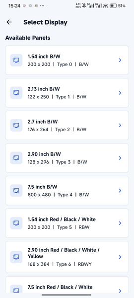
 2.6. Select the Corresponding E-Paper Display
Select the display model according to the actual e-paper size, resolution, and color mode.
For example: 2.13 inch B/W, 122 × 250, Type 1.
Note: The selected display model must match the actual e-paper display, or the image may not display
correctly.
2.7. Read and Display an SD Card Image
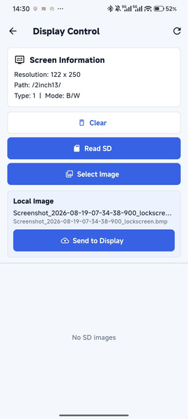
Confirm that the Micro SD card is formatted as FAT32 and inserted into the board.
On the Display Control page, check Screen Information and confirm that the image matches the actual display model.
Tap Send to Display. The image will be displayed and automatically uploaded to the corresponding SD card subfolder.
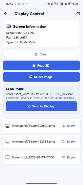
Click Read SD to load the image list from the SD card.
Tap Show beside the target image to display it on the e-paper screen.
Note: Use BMP images that match the display resolution and color mode.
2.8. Confirm Successful Display
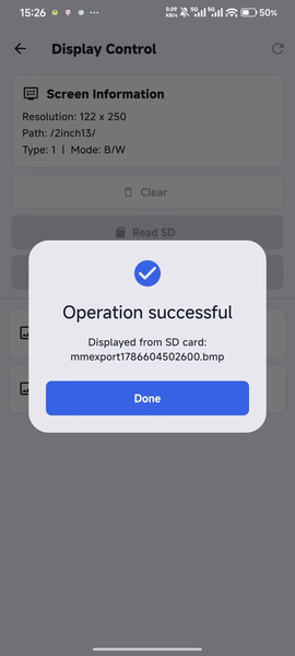
When the APP displays Operation successful, the display command has been executed successfully.Tap Done to close the message.
Check the e-paper display and confirm that the target image is shown correctly.
The APP Wi-Fi connection and SD card image display tests are now complete.