
I. Introduction
MPPT Solar Power Management Module, USB-C Bidirectional Fast Charging, 5V/5A Regulated Output, 2S 21700 Lithium Battery Charging
1.1 Product Overview
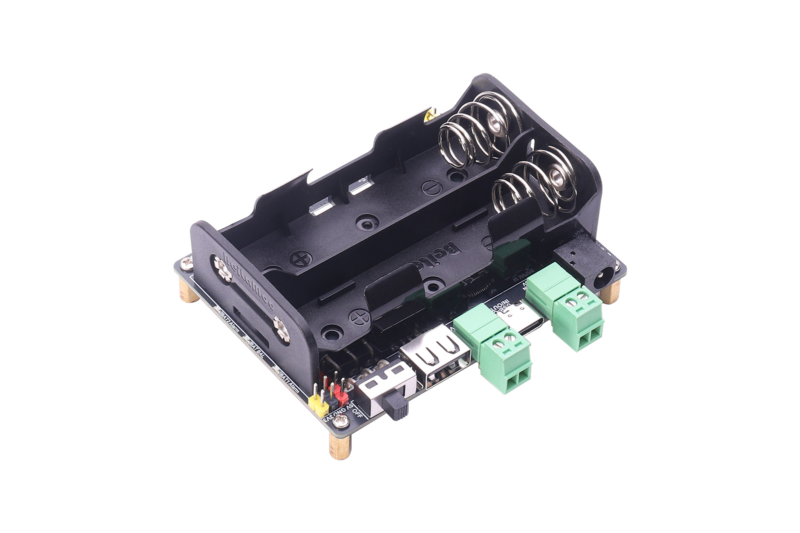
The Solar Energy Manager E is a solar power management module with fast charging capabilities. It supports charging two series-connected 3.7V 21700 lithium batteries via a solar panel or USB interface, and provides a regulated 5V/5A output (the Type-C port also supports multiple protocols including PD/QC/FCP/PE/SFCP). The module features MPPT (Maximum Power Point Tracking) and battery charge/discharge protection. MPPT automatically adjusts the charging power based on the input voltage for more efficient utilization of solar energy. The charge/discharge protection circuit monitors battery voltage in real time, preventing overcharge and over-discharge, thereby protecting the batteries and extending their lifespan. With its excellent stability and efficient charge/discharge management, it is ideal for solar power generation, low-power IoT, environmental monitoring, power banks, and other green energy projects.
1.2 Product Features
- CN3882 solar MPPT synchronous buck charger with three selectable solar operating points
- IP2369 45W-class USB-C bidirectional buck-boost fast charging subsystem
- Dual-cell independent protection with ETA3000 inductive active balancing
- Supports multiple charging sources: solar panel, power adapter, and USB-C PD adapter
- Onboard USB-A, USB-C, 3.81mm terminal blocks, and 2.54mm pin headers for voltage output; USB-C port supports bidirectional fast charging input/output
- Onboard multiple status LEDs for easy monitoring of battery charge/discharge status
- Supports simultaneous charging and discharging
- Onboard overcharge/over-discharge/reverse polarity/overcurrent/active balancing protection circuits for stable and safe operation
1.3 Product Specifications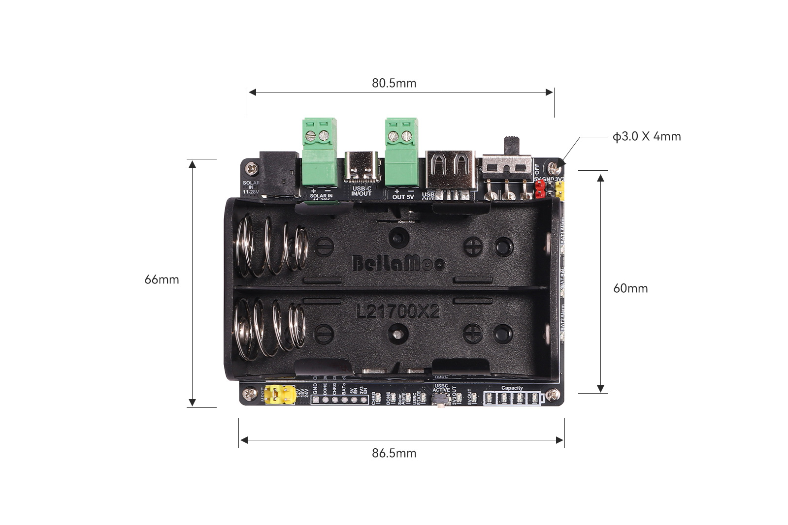
| Charging Sources | Power adapter, solar panel, USB-C PD power adapter |
| Supported Battery Type | 3.7V 21700 battery |
| Battery Operating Voltage | 6.0V ~ 8.4V (2 cells in series) |
| Solar Charging Input Voltage | 11V ~ 28V |
| USB-C Input/Output Voltage Levels | 5V/9V/12V/15V/20V (9V, 12V, 15V, 20V levels require PD fast charging protocol negotiation) |
| Charging Power | Solar: up to about 41W;USB-C: up to 45W |
| Discharge Power | 5A (USB A / 2P 3.81mm terminal block: 5V); 2A (3.3V)USB-C: up to 45W |
| Quiescent Current | about 10µA (battery switch OFF);about 10mA (battery switch ON) |
| Over-Discharge Protection Voltage | 6.0V ± 1% |
| Battery Charging Efficiency | Solar: up to about 92%;USB: up to about 94% |
| 5V Output Efficiency | about 93% |
| 3.3V Output Efficiency | about 93% |
| Dimensions | 86.5mm x 66mm |
II. Usage
2.1 Resource Overview
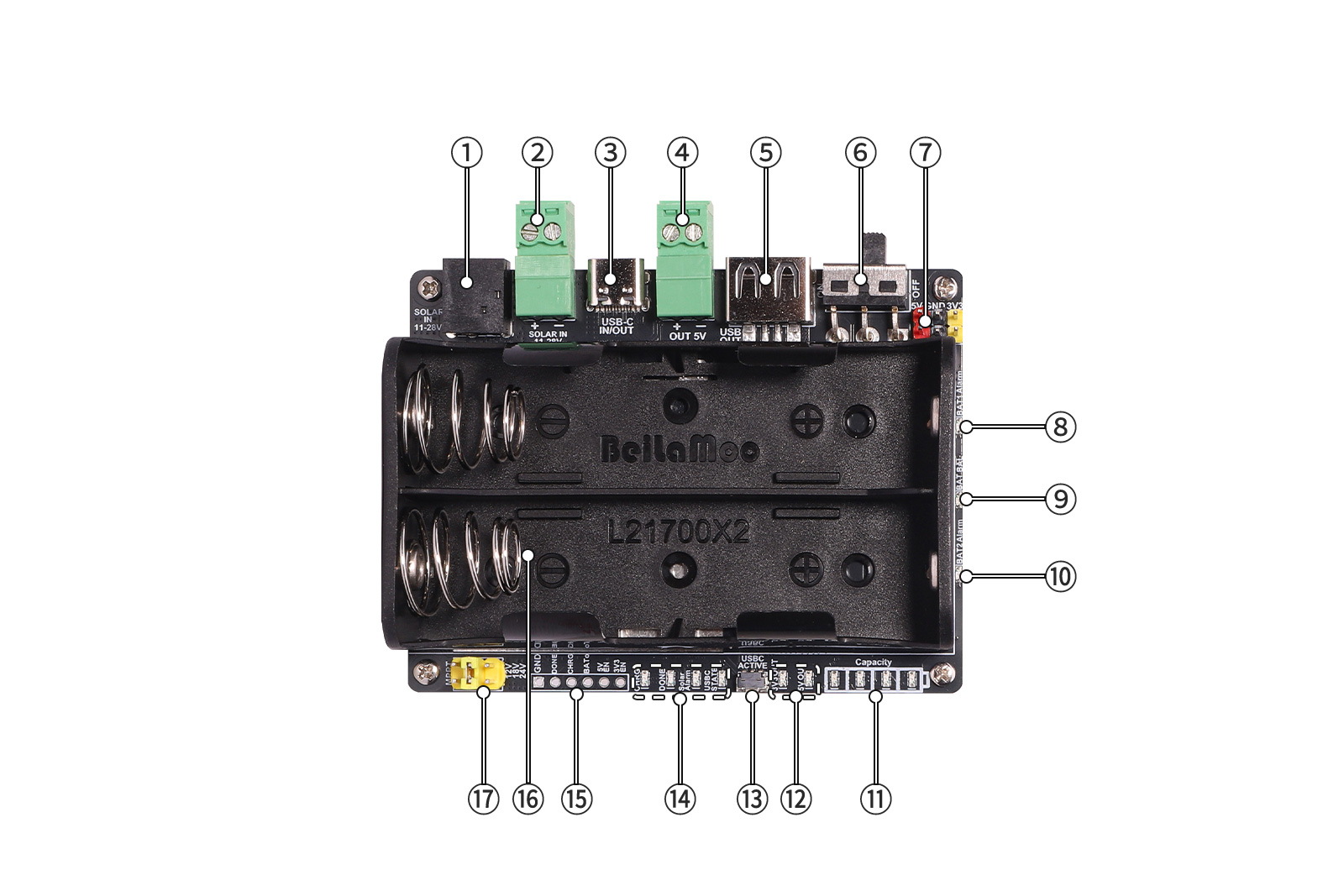
Figure 2-1 Solar Energy Manager E Resource Overview
(1)DC-044 Jack: Solar panel input
(2)3.81mm Terminal Block: Solar panel input
(3)USB-C Connector: Fast charging input/output interface
(4)3.81mm Terminal Block: 5V power output
(5)USB-A Connector: 5V power output
(6)Battery Switch: Set to "ON" for normal module operation
(7)2.54mm Output Pin Header: 5V and 3.3V output pins
(8)Battery 1 Reverse Polarity Indicator LED (Red)
(9)Battery Voltage Balancing Indicator: Illuminates when cells are being balanced
(10)Battery 2 Reverse Polarity Indicator LED (Red)
(11)Battery Voltage Indicator LEDs
(12)Power Output Indicator LED: 5V and 3.3V output indication
(13)USB-C Fast Charging Activation Button
(14)Other Indicator LEDs: CHRG (solar charging indicator); DONE (solar full charge indicator); Solar Alarm (solar input reverse polarity indicator); USB-C STATE (USB-C charge/discharge status indicator)
(15)Status Monitoring Pins (unpopulated 2.54mm 1×6P pads)
(16)2P 21700 Battery Holder
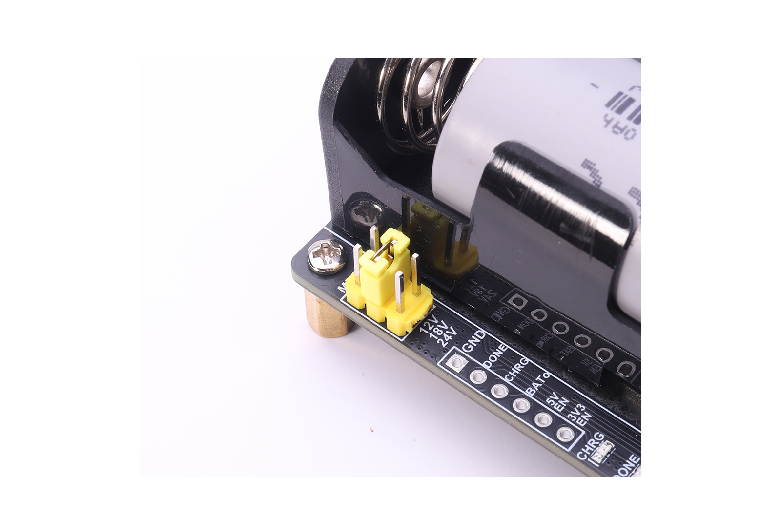
(17)MPPT Voltage Setting Jumper Pins
2.2 Interface and Function Description
1. Two Solar Panel Input Interfaces (① and ② in Figure 2-1):
DC-044 power jack and 3.81mm terminal block. These two connectors are directly paralleled internally. Do not connect power sources with different voltages simultaneously. Users should first set the appropriate MPPT voltage according to the solar panel's output voltage, then connect the solar panel to one of the two interfaces.
2. One USB Type-C Bidirectional Fast Charging Interface (③ in Figure 2-1):
Supports USB-C fast charging input and output. It can quickly charge the battery pack via this interface, and also supply power from the battery pack to devices such as smartphones and tablets through the USB-C port, with a maximum charge/discharge power of 45W. Supports PD3.1/PD3.0/PD2.0 and other fast charging protocols.
3. One IP2369 Activation Button (⑬ in Figure 2-1):
If no charging or discharging device is detected on the USB-C port for 10 consecutive seconds, the IP2369 enters low-power mode. A short press of this button wakes the IP2369 into no-load standby state; if a charging/discharging device is detected, it enters the corresponding state. In no-load standby, two short presses within 1 second will shut down the module into low-power mode and turn off the discharge output.
4. One Power Switch (⑥ in Figure 2-1):
When the module is not in use, set the switch to "OFF" to conserve battery power.
5. Active Battery Balancing:
The module features active battery balancing. When the voltage difference between the two cells reaches approximately 0.1V, the system automatically initiates balancing, reducing the voltage difference through energy transfer. During balancing, the BAT BAL indicator on the right side of the module illuminates; it turns off when balancing is complete.
For stable system operation, it is recommended to use batteries of the same model, capacity, and similar voltage when installing or replacing batteries. If the initial voltage difference is large, allow the module to idle until automatic balancing completes before normal charging/discharging.
6. Onboard Indicator LEDs
| LED Indicator | Description |
| CHRG (Red) | Lights steadily while solar charging is in progress |
| DONE (Green) | Lights steadily when solar charging is complete |
| Solar Alarm (Red) | Lights when the solar charging input polarity is reversed |
| USB-C STATE (Red) | When charging the battery via the USB-C port, the indicator flashes. Once the battery is fully charged, the indicator remains steadily lit. |
| When supplying power through the USB-C port, the indicator remains steadily lit. | |
| 3V3 OUT (Red) | Solid ON when 3.3V output is active |
| 5V OUT (Red) | Solid ON when 5V output is active |
| Battery Voltage Indicators(4 Red LEDs) | The more LEDs that are lit from left to right, the higher the battery voltage. When the battery voltage is very low, the leftmost LED flashes and the other LEDs remain off |
7. The board supports simultaneous charging and discharging. The USB-A connector does not support fast charging and is intended as a standard 5V power port.
8. Solar Charging Power: The charging power is higher when the battery level is lower, and when the solar panel output power is higher. With sufficient solar panel output and low battery level, the maximum charging power is approximately 41W.
9. Unpopulated 6-Pin Monitoring Pads at the bottom of the board for connecting external monitoring systems. Pin definitions:
| Pin | Signal | Direction | Electrical Characteristics & Usage |
|---|---|---|---|
| 1 | GND | Ground | External MCU must share common ground with this board |
| 2 | DONE | Output | Solar charge completion status, active low, 3.3V logic domain, read-only |
| 3 | CHRG | Output | Solar charging in progress, active low, 3.3V logic domain, read-only |
| 4 | BATo | Analog Output | Battery total voltage divider signal. Top resistor: 100KΩ, bottom resistor: 56KΩ, max ~3.0V, connect to MCU ADC |
| 5 | 3V3_EN | Control | 3.3V output enable, pulled high by default (enabled); pulling low disables 3.3V output |
| 6 | 5V_EN | Control | 5V output enable, pulled high by default (enabled); pulling low disables both 5V and 3.3V outputs |
10. About Full Charge Voltage:
Due to factors such as cell consistency, internal resistance, battery protection circuitry, connection voltage drops, and component tolerances, the actual charge cutoff voltage may vary. Therefore, after charging is complete, the total battery pack voltage is typically in the range of 8.2–8.4V and may not stabilize at a fixed value.
2.3 Product Usage
CAUTION:
- Never connect a power source with voltage exceeding 28V to this module.
- Observe correct polarity when installing batteries and connecting the solar panel. Do not reverse the connections.
- Avoid touching the core components directly with bare hands during operation. Take ESD precautions.
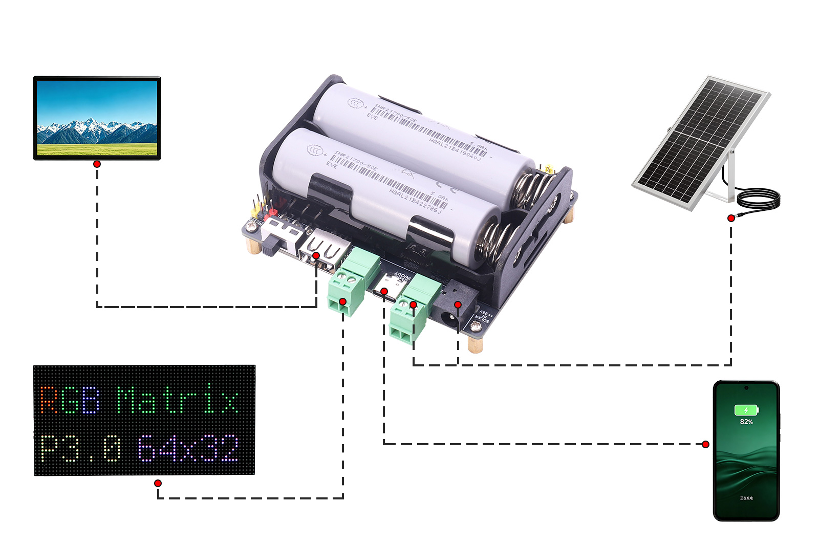
2.4 Related Operating Instructions
- Before charging or discharging, install the batteries with correct polarity, ensure the batteries are in a balanced state, set the battery switch to ON, and then proceed with charge/discharge operations.
"MPPT" Jumper Settings: When charging from a solar panel, the MPPT jumper must be correctly set. The jumper pins from left to right correspond to 12V, 18V, and 24V level. Use the shunt jumper to short only one of these positions; leave the others open. The MPPT voltage should be set according to the solar panel specifications. Charging efficiency is highest when the solar panel's Vmp voltage closely matches the MPPT setting, provided that the solar panel output voltage is greater than or equal to the MPPT set voltage, and the Voc must be less than 28V to avoid damaging the module. The factory default MPPT setting is 18V. Change to another value if needed.
- Vmp: Maximum Power Point Voltage – the operating voltage at which the solar panel delivers maximum power.
- Voc: Open-Circuit Voltage – the voltage measured when the solar panel is under no load and output terminals are left open.
Example MPPT setting shown below:
3. Battery Low-Voltage Protection:High-current loads can cause a significant instantaneous voltage drop in the battery. Under continuous discharge, the system may prematurely trigger undervoltage protection and cut off output. After a period of rest, the battery voltage will gradually recover and the device will automatically restore power.