I. Description
1.1 Product Overview
This product uses the ESP32-S3 as the main controller, features an onboard HUB75 interface, and can directly connect to HUB75 RGB LED matrices for display control. It also includes a Micro SD card slot for storing images, audio, and other files, enabling offline content playback. The onboard ES7210 audio ADC chip enhances voice processing, while the ES8311 low-power audio codec supports high-quality audio input/output. Dual silicon microphones and a speaker interface enable voice interaction applications. The onboard RTC real-time clock chip and reserved SH1.0 connector for a battery support time retention after power-off. Reserved ESP32-S3 debug and expansion pins (TX0, RX0, IO45, IO46, RST, BOOT) facilitate serial debugging, firmware download, function expansion, and system reset control.1.2 Product Features
- Onboard ESP32-S3-WROOM-1-N16R8 module with Xtensa® 32-bit LX7 dual-core processor, up to 240MHz, supporting 2.4GHz Wi-Fi and Bluetooth 5 LE; 16MB Flash and 8MB PSRAM – ideal for RGB LED matrix display, image/animation caching, audio interaction, and IoT applications.
- Two HUB75 interfaces: one for ribbon cable connection, one for direct plug-in – flexible connection options for displaying text, images, animations, clocks, status info, etc.
- Two Type-C ports: one for board power, matrix power, and program download/debugging; another (Power Type-C) dedicated for powering the HUB75 RGB LED matrix only.
- VH-4P terminal for supplying 5V power to the RGB LED matrix.
- ES7210 chip for enhanced voice processing.
- ES8311 low-power audio codec for high-quality audio input/output.
- Dual silicon microphones and speaker interface for sound capture, playback, and voice interaction.
- Micro SD card slot for storing images and audio files – supports offline display, media playback, and local data logging.
- PCF85063 RTC real-time clock chip with battery connector for time retention after power-off.
- I2C expansion interface for additional functionality.
- 3-way thumb wheel switch, EN/BOOT buttons, and breakout pins for BOOT, RST, IO45, IO46, TXD, RXD – easy debugging, expansion, and project integration.
1.3 Product Parameters
| Parameter | Description |
|---|---|
| Model | RGB Matrix HUB75 S3 |
| Supply Voltage | 5V |
| Power Input Interfaces | Two Type-C 5V inputs (one for board, one dedicated for matrix) |
| Power Output Interface | VH-4P (3.96mm pitch), max 5V/4A |
| RGB LED Matrix Interface | HUB75 |
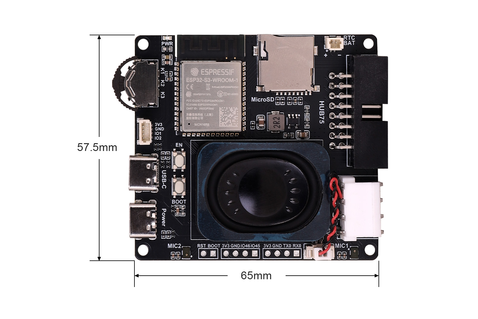
| Mounting Hole Diameter | 2.5mm |
| Dimensions | 65mm(L) x 57.5mm(W) |
II. Usage
2.1 Module Resources
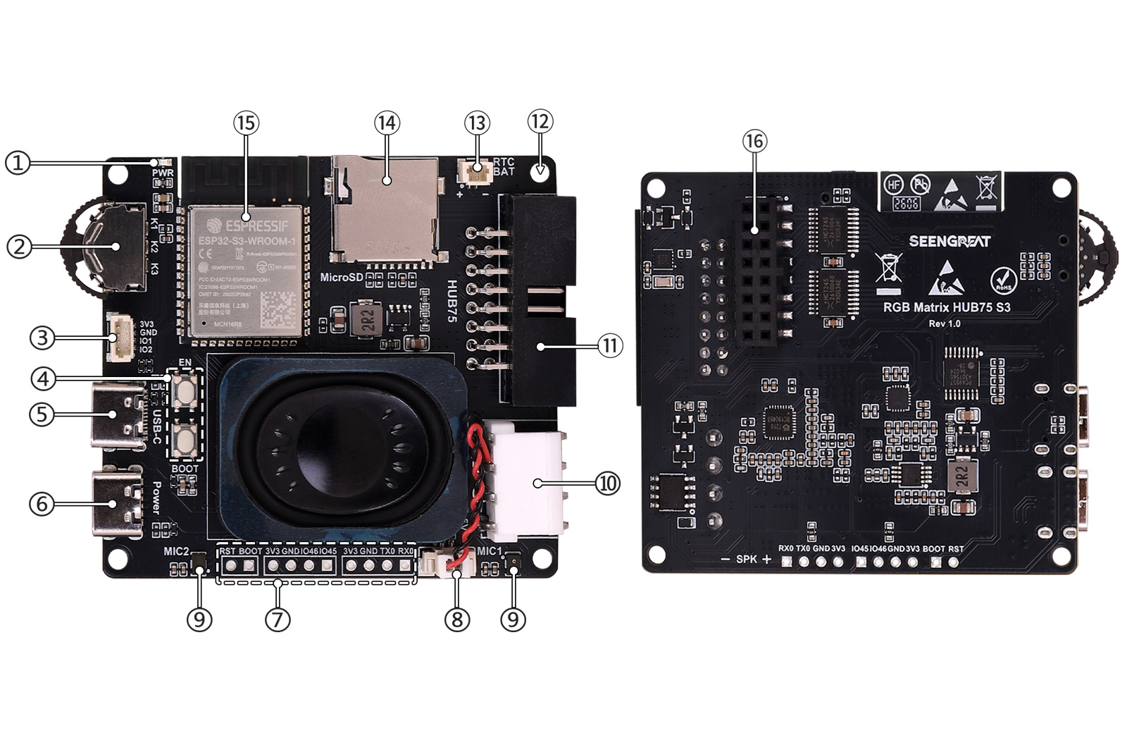 1. Power indicator
2. 3-way thumb wheel switch (PCA9557 expanded keys)
3. 1mm pitch 4-pin I2C expansion connector (SDA = IO1, SCL = IO2)
4. EN / BOOT buttons (EN = reset, BOOT = download mode)
5. USB-C interface (board power, download, debug)
6. Power Type-C interface (dedicated matrix power)
7. Breakout pins: BOOT, RST, IO45, IO46, TXD, RXD
8. Speaker connector
9. Dual microphones10. VH-4P connector (matrix power)
11. HUB75 connector (box header for ribbon cable)
12. M2.5 mounting holes
13. SH1.0 connector (RTC battery)
14. Micro SD card slot
15. ESP32-S3-WROOM-1-N16R8
16. HUB75 connector (2×8 pin header with bumps for direct plug-in)
2.2 Usage Instructions
2.2.1 Functions and Pin Mapping
- The onboard HUB75 LED matrix interface can connect to common HUB75 RGB LED matrix panels, and is used to display text, images, animations, clocks, status information, and other content. The board provides two types of HUB75 interfaces: a 2×8 box header (female) for standard ribbon cable connection, and a 2×8 pin header with bumps for direct plug-in connection, allowing flexible installation options.
| Interface Type | Description |
|---|---|
| Box header (2×8) | For standard HUB75 ribbon cake |
| Pin header with bumps (2×8) | For direct plug-in connection |
Figure: Example installation on a 64×64 RGB matrix board
The pin mapping between the HUB75 interface and the ESP32 is shown below:
| Mark | Pin Description | ESP32 Pin | Mark | Pin Description | ESP32 Pin |
|---|---|---|---|---|---|
| R1 | R higher bit data | IO05 | G1 | G higher bit data | IO04 |
| B1 | B higher bit data | IO06 | GND | Ground | GND |
| R2 | R lower bit data | IO15 | G2 | G lower bit data | IO07 |
| B2 | B lower bit data | IO17 | E | E line selection | IO16 |
| A | A line selection | IO08 | B | B line selection | IO18 |
| C | C line selection | IO10 | D | D line selection | IO09 |
| CLK | Clock input | IO12 | LAT | Latch pin | IO11 |
| OE | Output enable | IO13 | GND | Ground | GND |
The pin mapping between the audio interface and the ESP32 is shown below:
| Mark | Pin Description | ESP32 Pin |
|---|---|---|
| MCLK | Master clock signal | IO38 |
| SCLK | I2S bit clock signal | IO48 |
| LRCK | I2S left-right channel clock signal | IO21 |
| DSDIN | I2S audio data input signal | IO14 |
| SDOUT | I2S audio data output signal | IO47 |
| NS4150_EN | Speaker amplifier enable pin, active high (default low) | IO3 |
The pin mapping between the Micro SD card slot and the ESP32 is shown below:
| Mark | Pin Description | ESP32 Pin |
|---|---|---|
| SD_MISO | SPI data input signal | IO42 |
| SD_CLK | SPI clock signal | IO41 |
| SD_MOSI | SPI data output signal | IO40 |
| SD_CS | SPI chip select signal | IO39 |
| Mark | Pin Description | ESP32 Pin |
|---|---|---|
| SDA | I2C data line | IO1 |
| SCL | I2C clock line | IO2 |
5. The onboard EN and BOOT buttons make it easy for users to download programs and perform debugging. The EN button is used to reset the ESP32-S3 and restart the program; the BOOT button is used to enter download mode, and together with the USB Type-C interface, allows firmware burning and program debugging. Additionally, the board reserves commonly used debug and expansion pins such as TX0, RX0, IO45, IO46, RST, and BOOT, facilitating serial debugging, function expansion, external control, and secondary development.
6. The onboard PCA9557 expansion chip is used to expand more I/O pins. The onboard 3-way thumb wheel switch is connected to the system via the PCA9557 expansion chip and can be used as a user input key. The PCA9557 chip is also responsible for controlling the enable pins of certain other chips.
| Mark | Pin Description | PCA9557 Pin |
|---|---|---|
| K1 | 3-way thumb wheel switch key 1 | IO1 |
| K2 | 3-way thumb wheel switch key 2 | IO3 |
| K3 | 3-way thumb wheel switch key 3 | IO2 |
2.3 Example Program Usage
Connect the board to the computer using a Type-C data cable. After successful connection, the corresponding device will appear in Device Manager, e.g., COM12.

2.3.1 Compiling and Uploading Example Programs on Arduino Platform
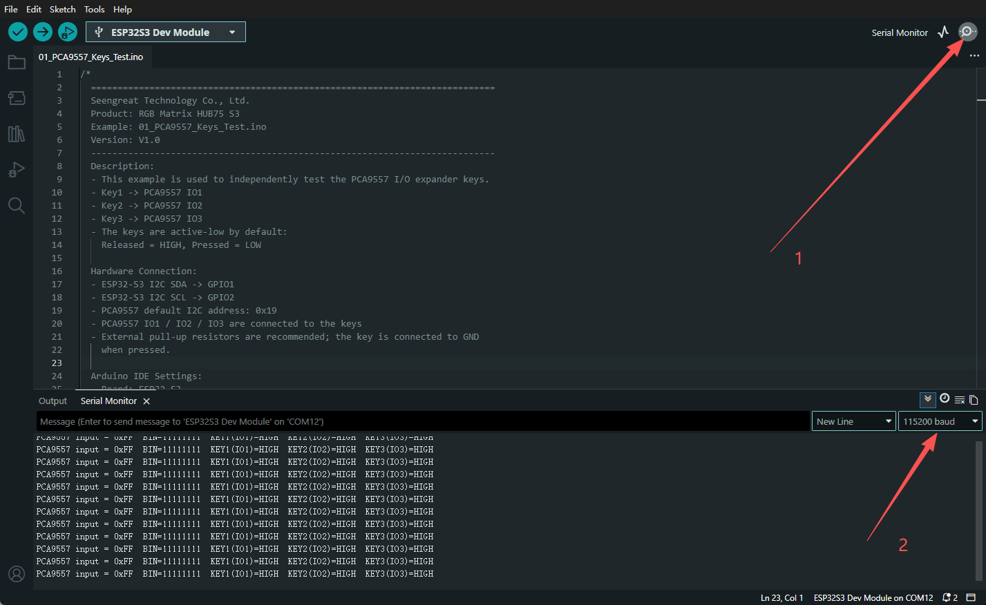
1. The software version used in this example is Arduino IDE 2.3.7. After launching the Arduino software, select Tools → Board → ESP32S3 Dev Module.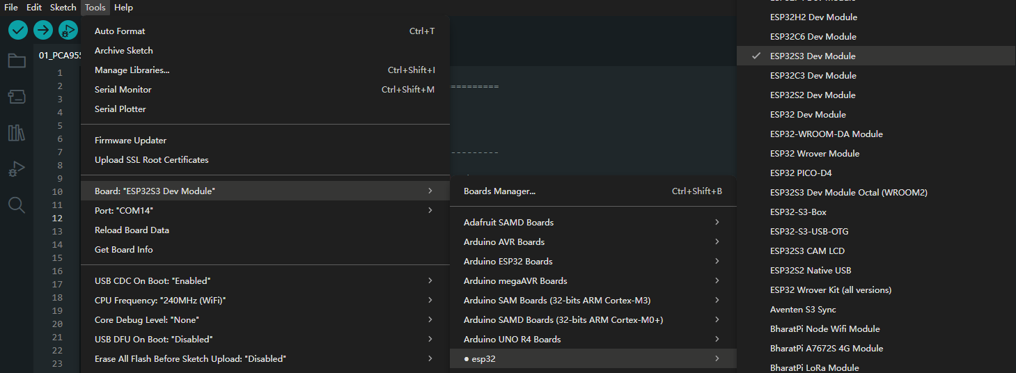
2. Select Tools → Port → COMx (select the corresponding COM port, e.g., COM12).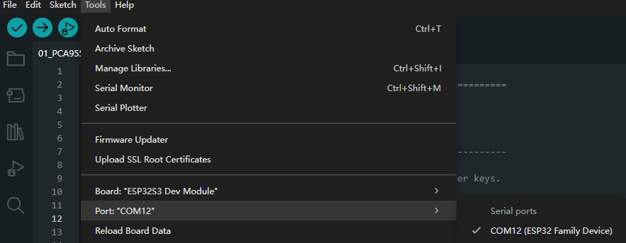
3. Select Tools → USB CDC On Boot → Enabled.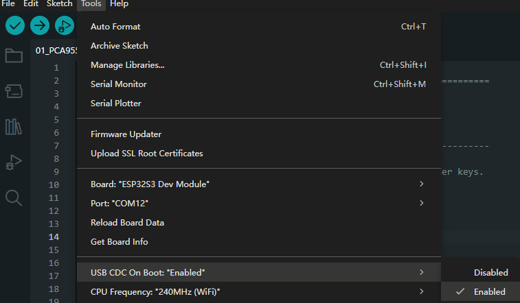
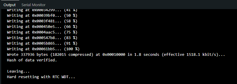
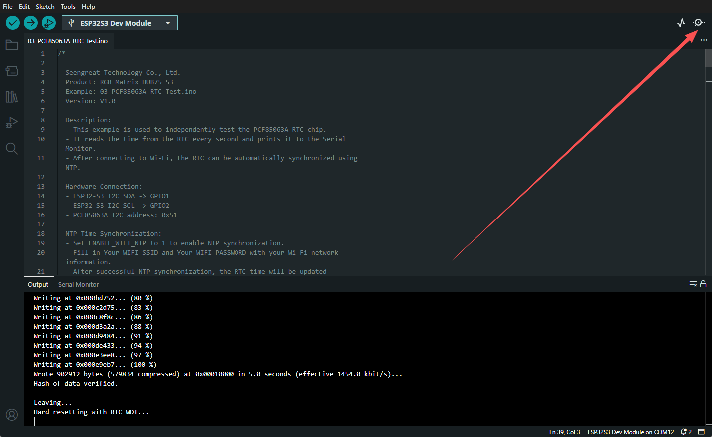
4. Click Upload.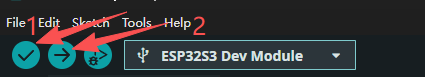 Wait for compilation and upload. A success message will appear as shown below.
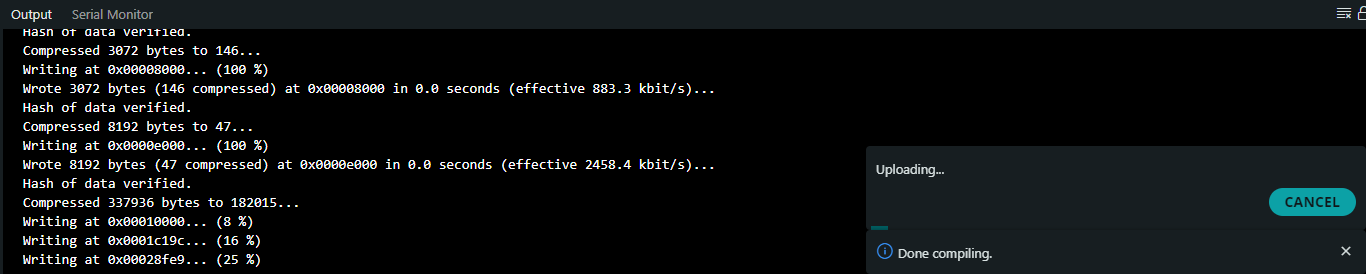
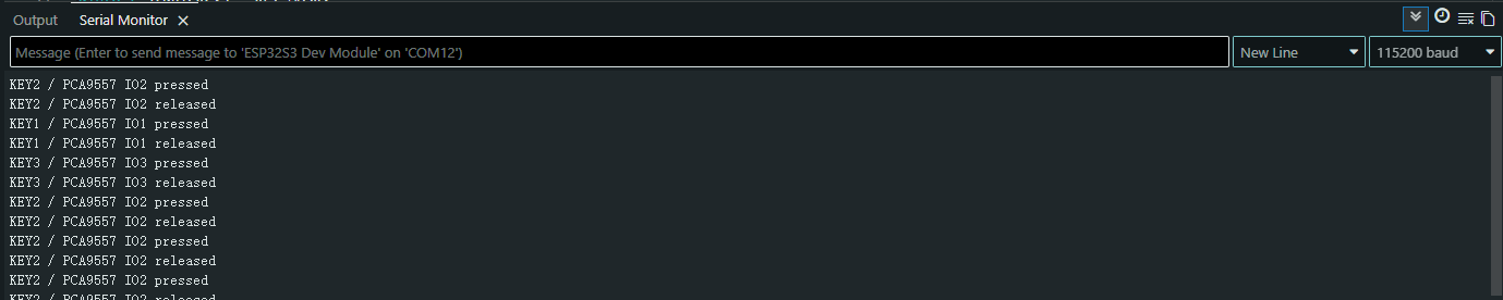
2.3.2 PCA9557 Key Expansion Function
Open the example program 01_PCA9557_Keys_Test.ino. Select the appropriate board and port, then compile and upload. After successful upload, open the Serial Monitor and set the baud rate to 115200. Relevant information will be printed in the window. Press the corresponding keys, and the window will print the corresponding key information.
2.3.3 Micro SD Card Reading Function
Open the example program 02_SD_Card_Read_Test.ino. Select the appropriate board and port, then compile and upload. After successful upload, open the Serial Monitor and set the baud rate to 115200. The window will print the file information currently on the SD card.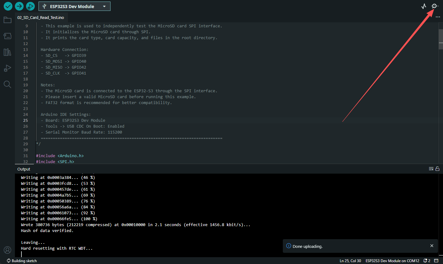
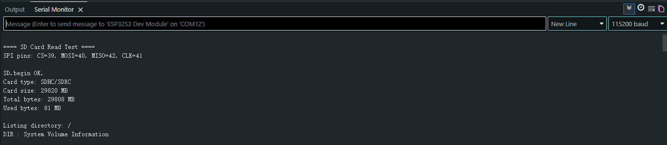
If the file information on the Micro SD card is not correctly read, please check whether the Micro SD card is formatted as FAT32.
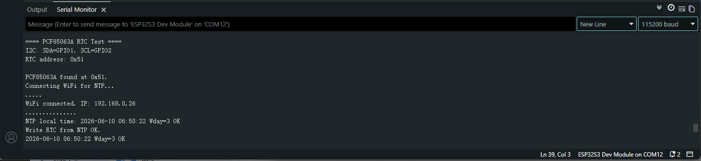
2.3.4 RTC Real-Time Clock Function
Open the example program 03_PCF85063A_RTC_Test.ino. To calibrate and obtain time via the internet, replace "Your_WIFI_SSID" and "Your_WIFI_PASSWORD" in the code with the correct Wi-Fi name and password. Select the appropriate board and port, then compile and upload. After successful upload, open the Serial Monitor and set the baud rate to 115200. The clock information will be printed in the window.
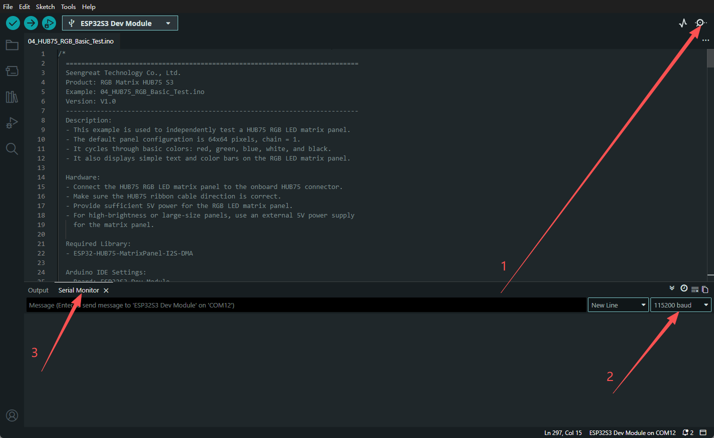
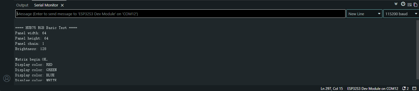
2.3.5 RGB LED Matrix Display Test
Open the example program 04_HUB75_RGB_Basic_Test.ino. This example is for a 64×64 RGB LED matrix. If you need to display on a different size matrix, please modify the corresponding section in the code. Select the appropriate board and port, then compile and upload. After successful upload, open the Serial Monitor and set the baud rate to 115200. The current display information will be printed in the window.
2.3.6 Voice Interaction Function
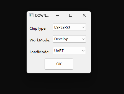
1.Download firmware using flash download toolThis example uses the tool flash_download_tool. Open the tool and select Chip Type: ESP32-S3. Keep other settings as default.
Note: When the flashing tool opens, two windows appear: one for device selection and one command-line black window. Do not close either window.
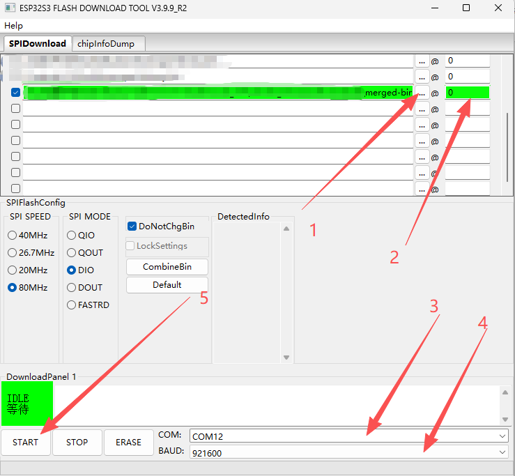
2. Flash the firmwareClick "..." to select the firmware path, locate the downloaded firmware file, and set the start address to 0.In the bottom right corner of the tool, find the COM option and set the download port. When the board is connected via data cable, two new COM ports should normally appear. Select either one. Below the COM port option is the BAUD option, used to set the download speed. It is recommended not to set it too high. Here, select 921600. After setting, click START to begin flashing. If flashing fails, click ERASE first, then try clicking START again.
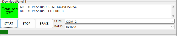
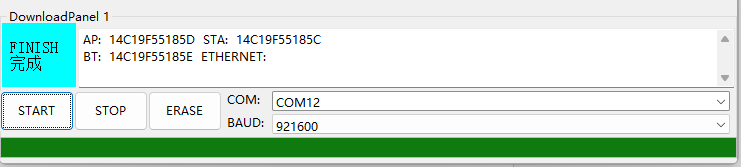
Wait for the firmware to finish flashing.
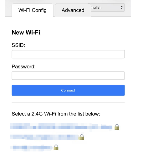
3. Wi-Fi provisioningOpen Wi-Fi settings. You will see a Wi-Fi hotspot named XiaoZhi-xxxx. This hotspot is emitted by the ESP32-S3 and has no password. Connect to it. After successful connection, the provisioning interface will automatically pop up. If it does not, open a browser on the device connected to the hotspot and enter 192.168.4.1 to access the provisioning page. Find the appropriate Wi-Fi network and connect.
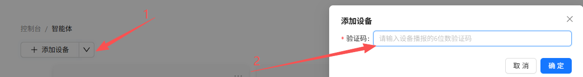
At this point, open a browser and go to xiaozhi.me. You can use a mobile phone or computer browser.Enter the XiaoZhi AI webpage, click Console, and log in using your phone number. Find "Add Device", then enter the 6-digit verification code displayed on the screen or announced by the board after successful provisioning.
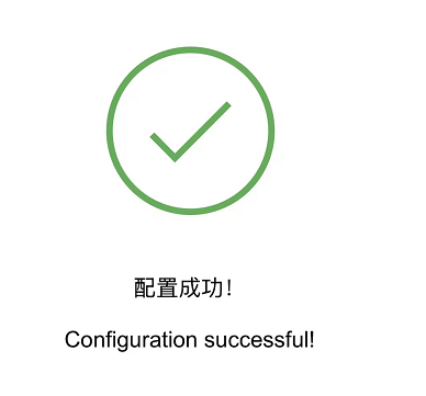
After successful configuration, restart the board to use the voice interaction function normally. You can say "Hi ESP" to wake up the voice assistant and start a conversation.
4. Display images from Micro SD card on the boardPrepare a Micro SD card formatted as FAT32. Create a new folder named gif on the SD card and place images inside. The image attributes need to be edited to the appropriate pixel size, such as 64×64 resolution. At this point, wake up the voice assistant and say commands like "show previous picture" or "show next picture" to control the image display.
5. Web control
Below the RTC clock display interface, there is an IP address. Open a browser on a device on the same local area network (LAN) and enter this IP address to access the web control interface.
6.Voice Interaction Firmware Function Description:
1. Button K1: Screen on/off control. A short press of K1 controls the RGB screen to be displayed or turned off.
2. Button K2: A short press of K2 switches to the clock display page; a long press of K2 enters reconfiguration mode.
3. Button K3: A short press of K3 switches the display of images on the SD card.
4. Web Control: After successful network configuration, the IP address obtained by the device can be viewed through a serial port assistant, or directly on the RGB screen. This IP address is assigned by the ESP32 device. Entering this IP address in the browser address bar will open the web control terminal for controlling the board's functions.
5. Voice Assistant Wake-up: The voice assistant can be activated using a voice wake-up phrase, such as "Hi ESP" or "Hello, Xiaozhi".
III. Resources
- Schematic
- Dome Codes
- Bin
- Flash download tools