I. Description
1.1 Product Overview
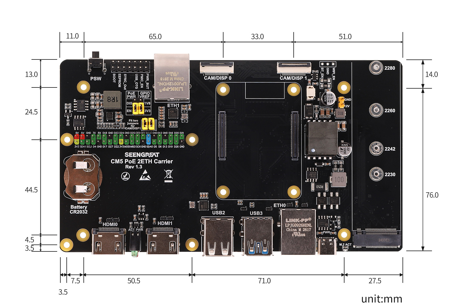
The CM5 PoE 2ETH Carrier is a multifunctional carrier board designed for the Raspberry Pi Compute Module 5. It integrates PoE power supply, dual Ethernet ports, M.2 NVMe SSD, dual HDMI, USB expansion, MIPI camera/display interfaces, RTC battery holder, fan interface, and 40-pin GPIO. It is suitable for industrial control, edge computing, network gateways, video capture, dual Ethernet communication, and embedded terminals. The onboard Gigabit RJ45 port supports PoE, enabling both network communication and power input via a single Ethernet cable, providing 5V system power and 12V power output. Another 100M RJ45 port is also provided for dual-network applications. The board supports M.2 M-Key NVMe SSDs for high-speed storage and system boot. It also retains CM5 peripheral interfaces, including two CAM/DISP connectors, dual HDMI outputs, USB3.0/USB2.0 ports, RTC battery holder, and fan interface, allowing users to quickly build a stable, compact, and feature-rich CM5 application platform.
1.2 Product Features
- Designed specifically for Raspberry Pi CM5: Provides complete interface expansion for Compute Module 5.
- PoE support: Gigabit RJ45 port supports PoE input, powers the entire board via Ethernet cable, ideal for network cabinets, gateways, surveillance, industrial deployment.
- Dual Ethernet ports: One Gigabit and one 100M RJ45 port for routing, gateway, network isolation, data acquisition.
- M.2 M-Key interface for NVMe SSD, supports high-speed storage and system boot.
- Dual HDMI outputs: HDMI0 and HDMI1 for display or debugging.
- Rich USB interfaces: Dual-stack USB3.0 Type-A and dual-stack USB2.0 Type-A for mouse, keyboard, USB drive, camera, wireless adapter.
- Dual MIPI camera/display interfaces: CAM/DISP 0 and CAM/DISP 1 for camera or DSI display, suitable for image capture and display.
- 40-pin GPIO header: Standard Raspberry Pi 40-pin GPIO for sensors, HATs, or custom peripherals.
1.3 Product Parameters
| Parameter | Description |
|---|---|
| Compatible Core Module | Raspberry Pi Compute Module 5 |
| Power Supply | PoE / USB-C |
| Network Interfaces | 1× Gigabit RJ45 (PoE input), 1× 100M RJ45 |
| USB Interfaces | 2× USB3.0 Type-A, 2× USB2.0 Type-A |
| Display Interfaces | 2× HDMI |
| Storage Expansion | MicroSD card slot (for non-eMMC version), M.2 M-Key NVMe SSD interface |
| MIPI Interfaces | 2× CAM/DISP interfaces |
| Fan Interface | 5V, 4-pin JST-SH PWM fan connector |
| RTC BAT | CR2032 RTC battery holder |
| Dimensions | 160mm × 90mm |
II. Usage
1.Warning : Do not plug/unplug any device except USB and HDMI while powered on.
2.When using PoE power supply, set the PoE jumper cap to the EN position, and disconnect the USB-C power supply beforehand. This PoE network port complies with IEEE 802.3af/at standards. Please verify that your switch supports these standards before use.
3.The USB-C port functions as a USB slave port for image flashing and board power input. It does not support power output or OTG mode.
4.When flashing the system via USB-C, do not connect any other devices. Otherwise, insufficient power may cause recognition failures. It is recommended to use a USB 3.0 port for best results.
2.1 Module Resources
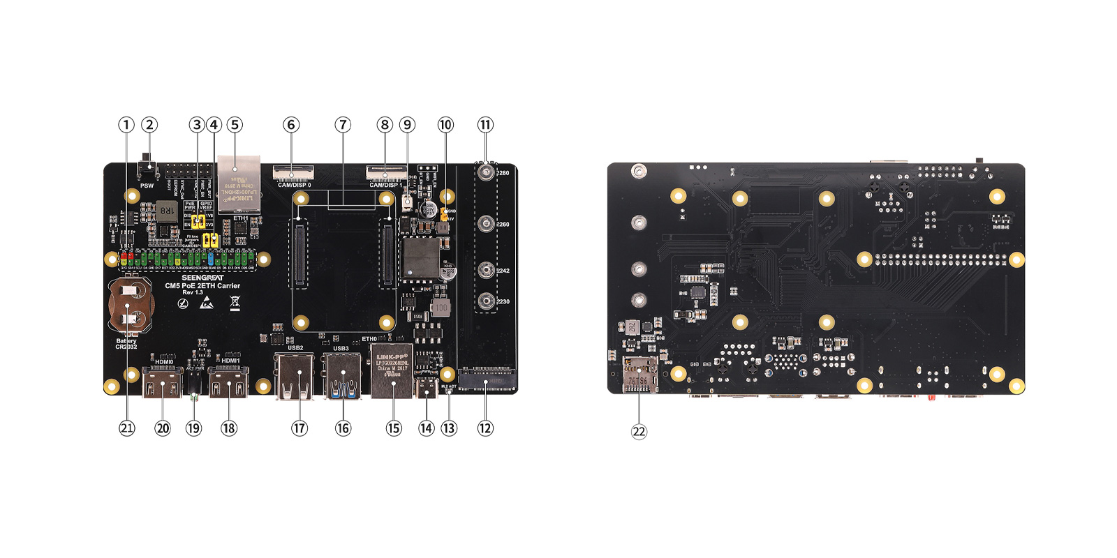
- Raspberry Pi 40-pin GPIO header
- CM5 power button
- PoE power enable and CM5 GPIO voltage selection jumper
- CAM/DISP 1 I2C pin selection jumper
- 100M RJ45 connector
- CAM/DISP 0 connector
- CM5 core module connector
- CAM/DISP 1 connector
- Fan connector
- PoE 12V power output
- M.2 NVMe SSD mounting hole
- M.2 M-Key connector
- M.2 NVMe activity LED (green)
- CM5 USB-C power input
- Gigabit RJ45 connector (PoE)
- Dual-stack USB3.0 Type-A
- Dual-stack USB2.0 Type-A
- HDMI 1 connector
- CM5 power status LED (red/green)
- HDMI 0 connector
- RTC battery connector
- MicroSD card slot (for CM5 Lite)
2.2 Usage Instructions
2.2.1 Raspberry Pi OS Burning
For the Lite version of the core module (without eMMC), it is recommended to use a MicroSD card reader to burn the image. After inserting the SD card into the computer, format it first. The burning process can refer to the Raspberry Pi Imager software burning instructions in this section.
The following are the image burning steps for the eMMC version of the core module:
After inserting the core module with the eMMC version, use a yellow jumper cap to short the BOOT pins. As shown in the figure below: (Temporarily shift the shorting cap on the I2C pin selection jumper header of the CAM/DISP 1 connector to the BOOT jumper header. After the system image flashing is finished, reinstall the shorting cap back to its original position.)
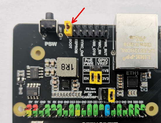
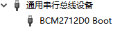
Then connect the computer (USB 3.0 recommended) to the onboard CM5 USB-C port (see 15 of Module Resources Figure in 2.1) using a Type-C cable. (At this time, do not connect any other devices to the board, such as HDMI, USB keyboard, USB mouse, etc.) The device "BCM2712D0 Boot" will appear in the computer's Device Manager. Then remove the yellow jumper cap from the BOOT pins.
 Then run the rpiboot software (users can install it themselves; download address: https://raw.githubusercontent.com/raspberrypi/usbboot/master/win32/rpiboot_setup.exe) and select "rpiboot-CM4-CM5 - Mass Storage Gadget".
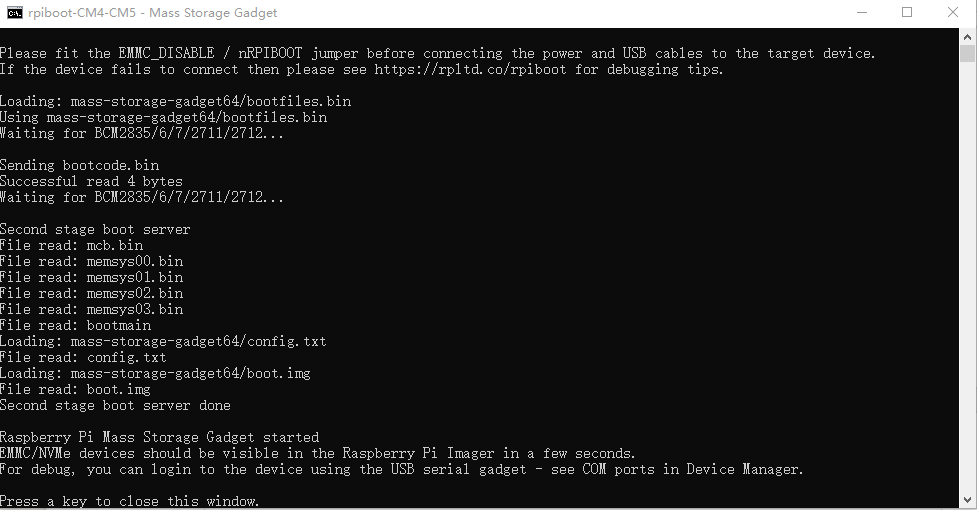
 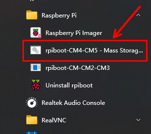 At this point, the following window will pop up:
 After the above information appears, run the Raspberry Pi Imager software (it is recommended to install a newer version; download address: https://www.raspberrypi.com/software/), select "Raspberry Pi 5" in the "Device" field, and then click "Next".
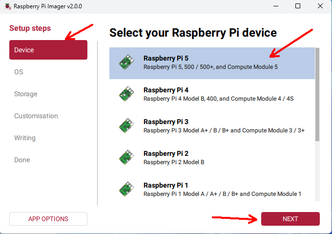 In the "OS" field, select the appropriate operating system, such as "Raspberry Pi OS (64-bit)", and then click "Next".
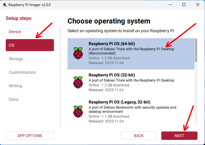 In the "Storage" field, select your image storage device, such as the SD card or the eMMC of the core module, and then click "Next".
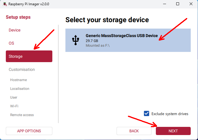 In the "Customisation" section, you can select "SKIP CUSTOMISATION" to skip system configuration for now, or you can follow the prompts to configure it in advance.
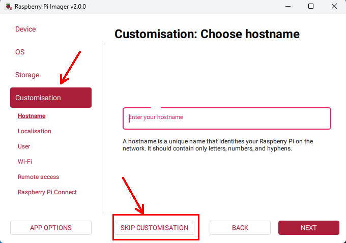 In the "Writing" section, you can select "WRITE".
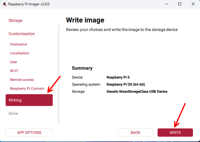 Click "I UNDERSTAND, ERASE AND WRITE".
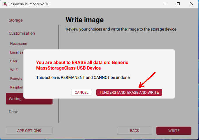 Wait patiently for the writing and verification to complete, then click "FINISH".
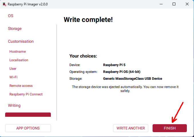 Unplug the USB cable, connect the mouse, keyboard, and HDMI display, then power on the device again.
2.2.2 Ethernet
The board has two RJ45 network interfaces: one 100Mbps port and one Gigabit port with PoE function. By default, the Gigabit port is recognized as eth0 and the 100Mbps port as eth1. After connecting an Ethernet cable to the board, you can use the ifconfig command to view the IP address and other information of the network interfaces.
When powering the carrier board via PoE, please set the PoE power jumper to the Enable (EN) position and disconnect the USB-C power input in advance, and then connect the PoE supply. This PoE interface is compatible with the IEEE 802.3af/at standard. This PoE supports IEEE 802.3af/at, with a maximum 5V output of 4.5A (via the 2.54mm 2x20P GPIO header) and a maximum 12V output of 2A (via the 2.54mm 1x2P yellow header).
If a current limit warning appears in the top-right corner of the screen after powering on, you can add the following line to /boot/firmware/config.txt:
usb_max_current_enable=12.2.3 PCIe
PCIe defaults to Gen 2. If you need to enable PCIe Gen 3, add the following line to /boot/firmware/config.txt:dtparam=pciex1_gen=32.2.4 MIPI
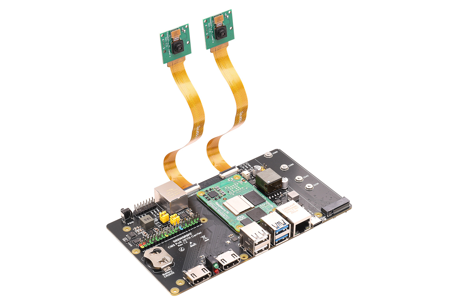
This test procedure requires connecting the camera or LCD display to the MIPI interface (CAM/DISP 0 or CAM/DISP 1) while the board is powered off. The camera model is OV5647, and the LCD screen model is Touch Display 2. Be careful not to use excessive force when inserting or removing the FPC cable to avoid damaging the MIPI connector. When using the CAM/DISP 1 interface, place the I2C pin selection jumper (see 4 of Module Resources Figure in 2.1) in the shorted state.
Camera:
Configure the following in /boot/firmware/config.txt:
dtoverlay=ov5647,cam0
dtoverlay=ov5647,cam1
Save the configuration and then power off the board.
Connect two cameras to the board as shown in the figure below (pay attention to the orientation of the FPC cables):
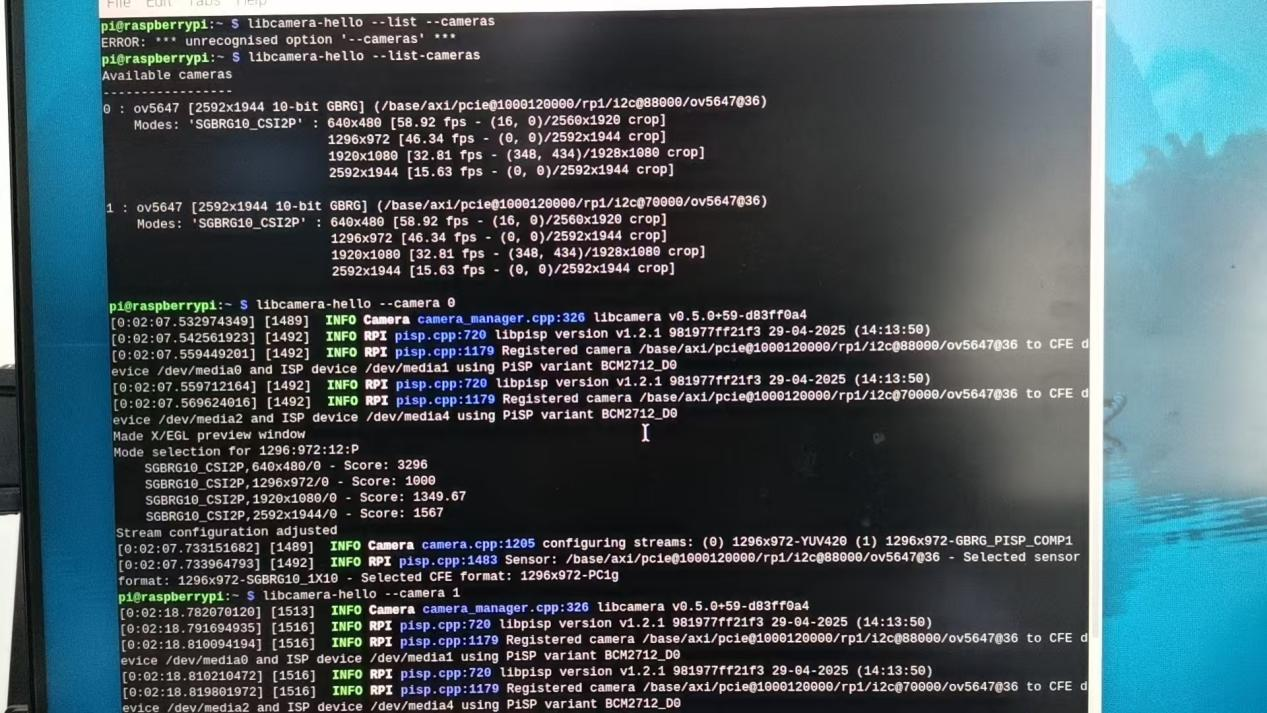
 After powering on and booting up, enter the commands in the terminal.
libcamera-hello  --list --cameras
libcamera-hello  --camera 1
libcamera-hello  --camera 0
Under normal circumstances, both cameras can be recognized and previewed normally.
 Display and Camera:Configure the following in /boot/firmware/config.txt:
dtoverlay=ov5647,cam1
dtoverlay=vc4-kms-dsi-ili9881-7inch,dsi0as shown in the figure: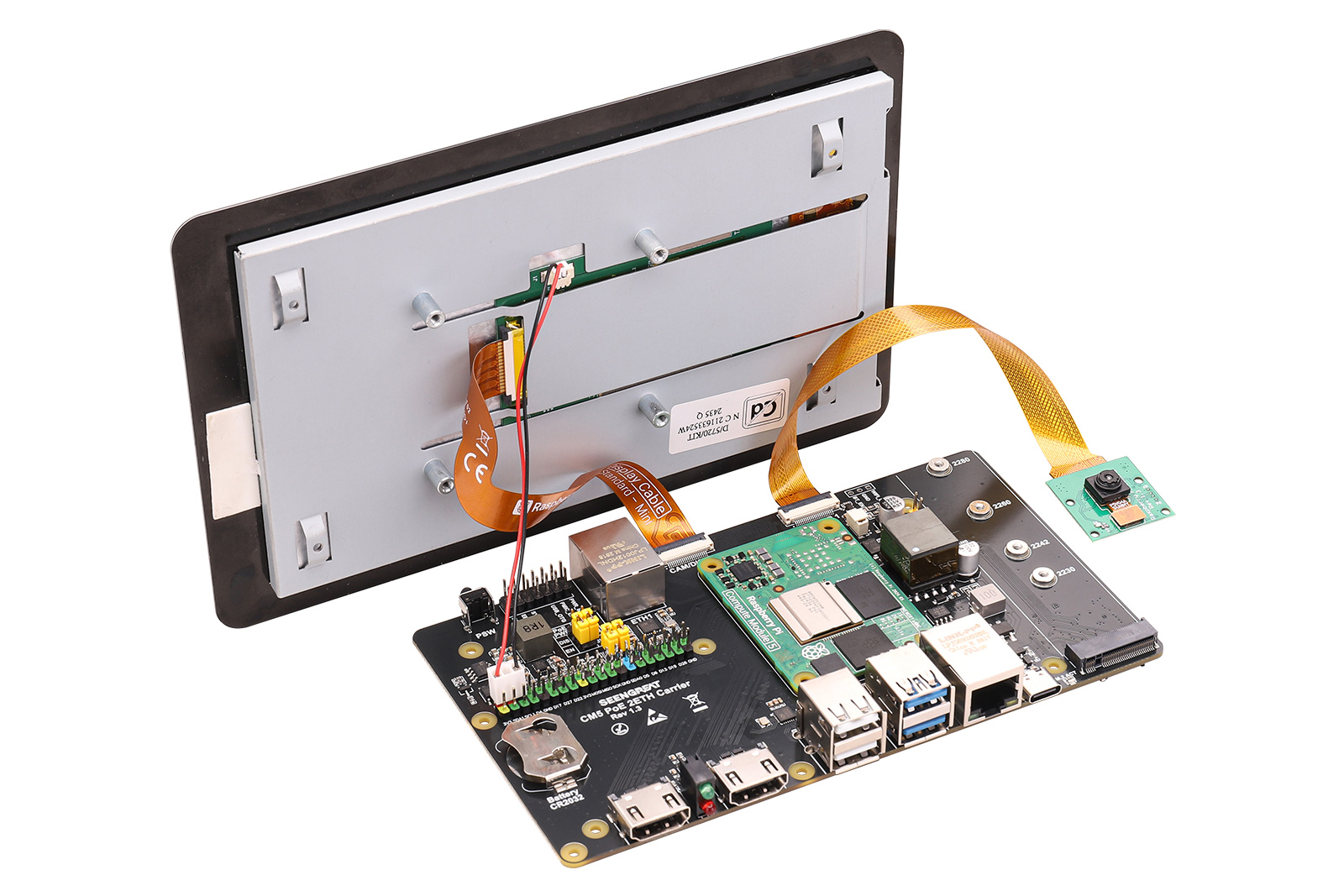
After connecting everything, power on the board. After booting, both the Touch Display 2 screen and the HDMI display will show output. In the terminal, use the libcamera-hello --list-cameras and libcamera-hello commands to detect and preview the camera "0: ov5647...".
2.2.5 Fan
Connect the fan to the fan interface (insert it into the connector shown in 9 of Module Resources Figure). The Pi5 fan is set by default to start spinning only when the temperature reaches 50°C. If you want the fan to start spinning at other temperatures, you can add the following content to /boot/firmware/config.txt and then reboot. For example:
dtparam=fan_temp0=36000,fan_temp0_hyst=2000,fan_temp0_speed=90
dtparam=fan_temp1=40000,fan_temp1_hyst=3000,fan_temp1_speed=150
dtparam=fan_temp2=52000,fan_temp2_hyst=4000,fan_temp2_speed=200
dtparam=fan_temp3=58000,fan_temp3_hyst=5000,fan_temp3_speed=255
In principle, this configuration makes the fan speed increase as the CPU temperature rises. You can use the vcgencmd measure_temp command in one terminal to check the CPU temperature, and in another terminal, run the stress -c 4 command to increase the CPU load. The higher the load, the higher the CPU temperature, and the fan speed will increase accordingly. In the terminal where stress -c 4 is running, press Ctrl+C to stop the command. After that, you will see the CPU temperature drop, and the fan speed will gradually decrease as well.
2.2.6 RTC
Insert the RTC coin cell battery into the battery connector (see 21 of Module Resources Figure)). After powering on, set the RTC clock in the terminal:
sudo hwclock --set --date="2026-1-1 12:12:00"sudo hwclock -s # The network needs to be disabled or network time synchronization turned off, otherwise the time will be changed backAt this point, the time shown by the date command and the time in the top-right corner will be synchronized with the clock set above. Then disconnect the power from the Raspberry Pi, wait a moment, and power it on again. The system clock in the top-right corner will not be the previously set clock, but the RTC clock will still be the one you set (you can check this with the sudo hwclock -r command).
The reason for this time mismatch is that the system does not automatically sync the hwclock time to the system time. You can manually create a service:
sudo nano /etc/systemd/system/rtc-sync.service[Unit]
Description=Sync hardware clock to system time
After=sysinit.target
Before=network.target
[Service]
Type=oneshot
ExecStart=/sbin/hwclock --hctosys --utc
[Install]
WantedBy=multi-user.targetsudo systemctl enable --now rtc-sync.servicesudo hwclock -r command. You will see that the displayed time is consistent with the time in the top-right corner of the screen or the time shown by the date command.