 I. Introduction
1.1. Product Introduction
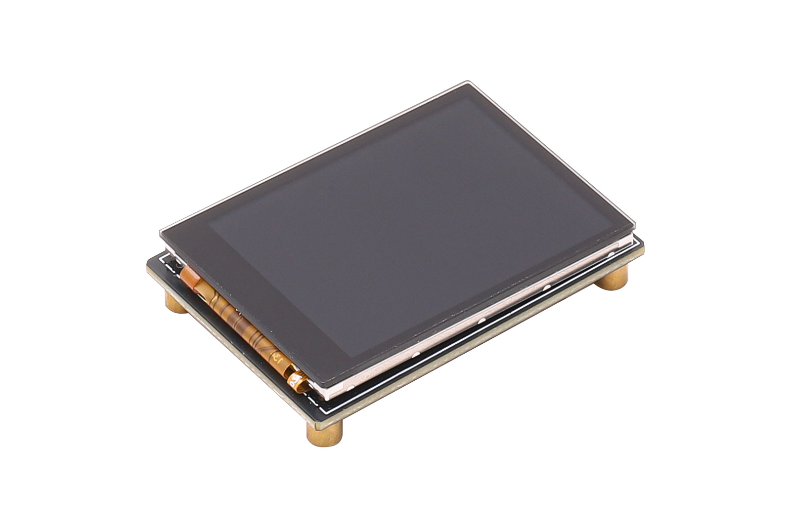
2-inch capacitive touch screen, display driver ST7789P3, touch driver CST816D, 320×240 resolution.This is a 2-inch capacitive touch screen driver board designed for embedded display applications, paired with a 2.0-inch TFT LCD module. It supports 320×240 resolution, color images, text, menu interfaces, and touch interaction.
The display uses the ST7789P3 driver IC, and the touch part uses the CST816D touch IC. The LCD is controlled via SPI, and the capacitive touch communicates with the host via I2C, making it easy to interface with platforms such as STM32, ESP32, Arduino, and Raspberry Pi.
1.2. Product Features
- 2.0-inch color display with 320×240 resolution
- Display driver IC: ST7789P3, SPI interface
- Capacitive touch IC: CST816D, I2C interface
- Supports 262K colors for colorful icons, buttons, and GUI
- Onboard level shift IC, supports 3.3V and 5V operating voltage
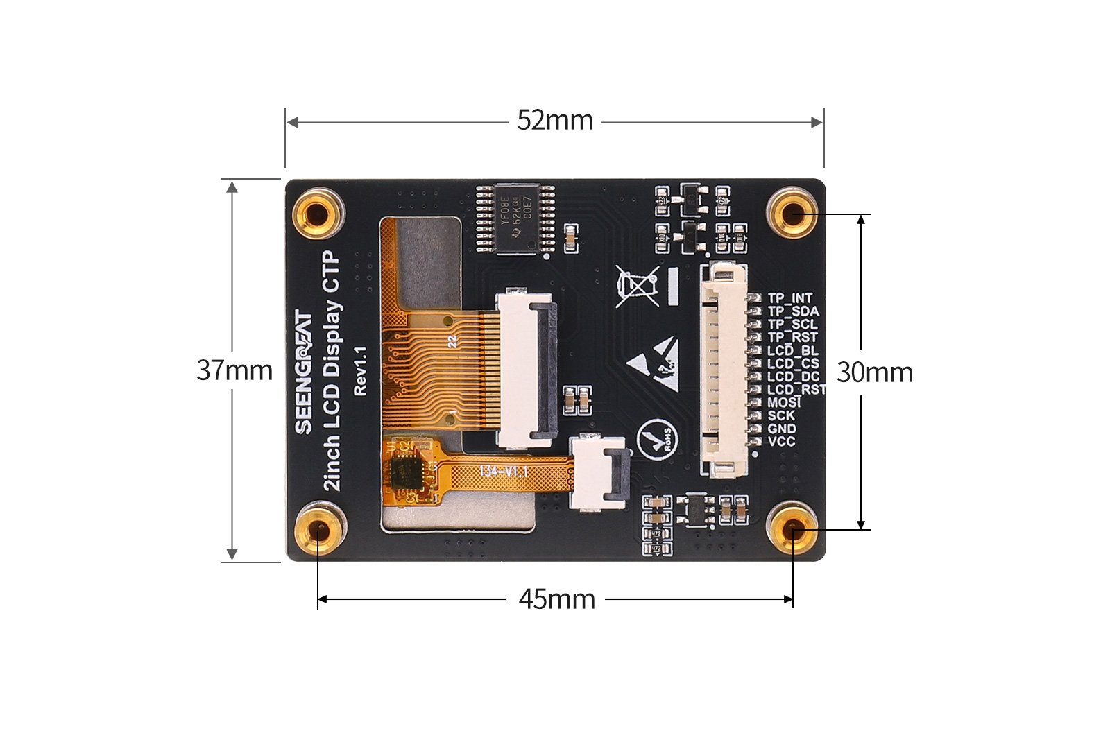
1.3. Product Specifications
| Parameter | Value |
|---|---|
| Dimensions | 52mm × 37mm |
| Resolution | 320 × 240 |
| Display Colors | RGB 262K |
| Display Interface | SPI |
| Touch Interface | I2C |
| Display Driver IC | ST7789P3 |
| Touch Controller IC | CST816D |
| Viewing Area | 40.8mm × 30.6mm |
| Supply Voltage | 3.3V / 5V |
1.4. Module Resources
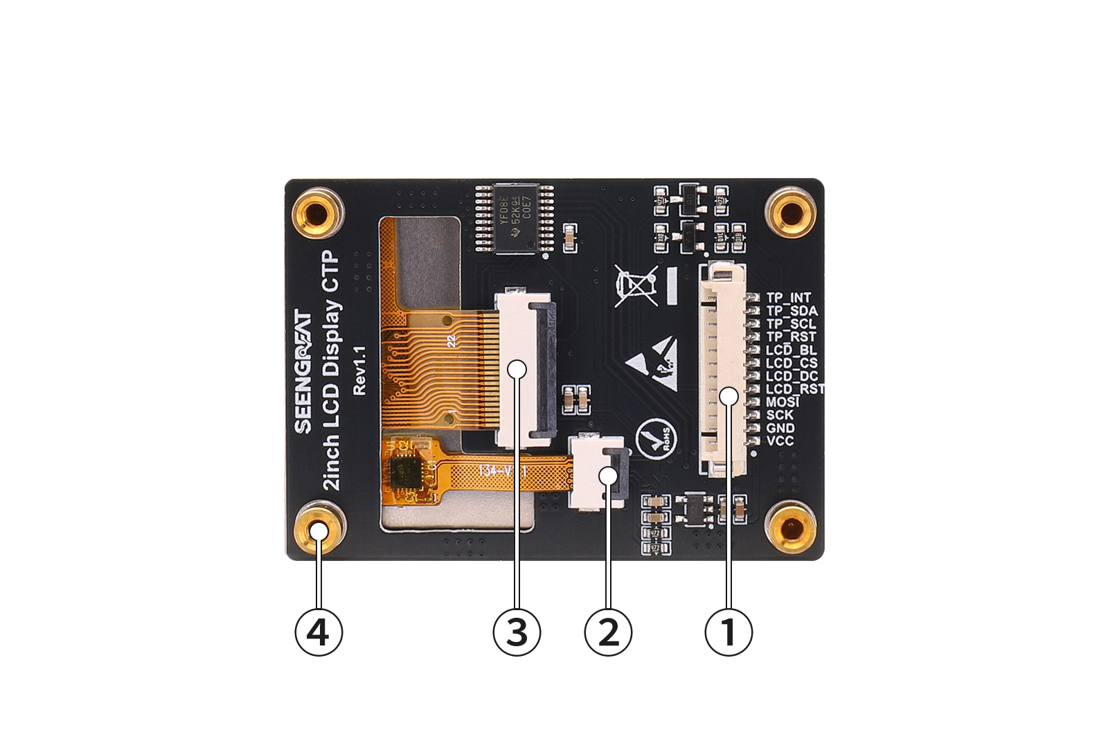
①Control Interface: 1.25mm pitch 12P connector
②Capacitive Touch FPC Connector
③LCD Screen FPC Connector
④M2.5 SMD Copper Standoff
1.5. Pin Definition
| Pin Name | Description |
|---|---|
| VCC | Power Positive |
| GND | Power Ground |
| SCK | SPI Clock |
| MOSI | SPI Data Output |
| LCD_RST | LCD Reset |
| LCD_DC | LCD Data/Command Select |
| LCD_CS | LCD Chip Select |
| LCD_BL | LCD Backlight Control |
| TP_RST | Touch Reset |
| TP_SCL | Touch I2C Clock |
| TP_SDA | Touch I2C Data |
| TP_INT | Touch Interrupt |
II. Usage
2.1 Hardware Description
2.1.1 Pin Definitions
| Pin Name | Description |
|---|---|
| VCC | Power Positive |
| GND | Power Ground |
| SCK | SPI Clock Signal |
| MOSI | SPI Data Output |
| LCD_RST | LCD Reset Signal |
| LCD_DC | LCD Data/Command Select |
| LCD_CS | LCD Chip Select |
| LCD_BL | LCD Backlight Control |
| TP_RST | Touch Reset Signal |
| TP_SCL | Touch I2C Clock |
| TP_SDA | Touch I2C Data |
| TP_INT | Touch Interrupt |
2.2 Arduino Demo Code
2.2.1 Connecting to Arduino UNO
Connect the board to Arduino UNO according to the following table:| Pin Name | Arduino UNO | Description |
|---|---|---|
| VCC | 5V | Power Positive |
| GND | GND | Power Ground |
| SCK | D13 | SPI Clock Signal |
| MOSI | D11 | SPI Data Output |
| LCD_RST | D8 | LCD Reset Signal |
| LCD_DC | D9 | LCD Data/Command Select |
| LCD_CS | D10 | LCD Chip Select |
| LCD_BL | D6 | LCD Backlight Control |
| TP_RST | D4 | Touch Reset Signal |
| TP_SCL | A5 | Touch I2C Clock |
| TP_SDA | A4 | Touch I2C Data |
| TP_INT | D2 | Touch Interrupt |
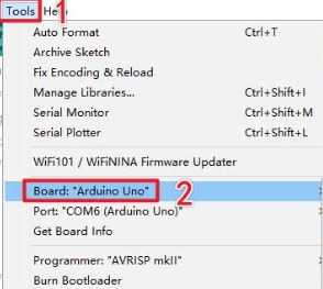
2.2.2 Uploading the Code
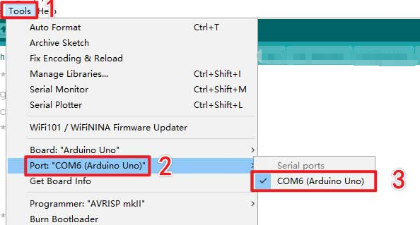
Select the board model and port number as shown below:
 After selection, click compile and upload the code to Arduino UNO.
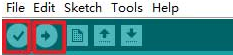 You will see the screen display lines, rectangles, filled blocks, circles, and characters, and then enter the touch function display interface.
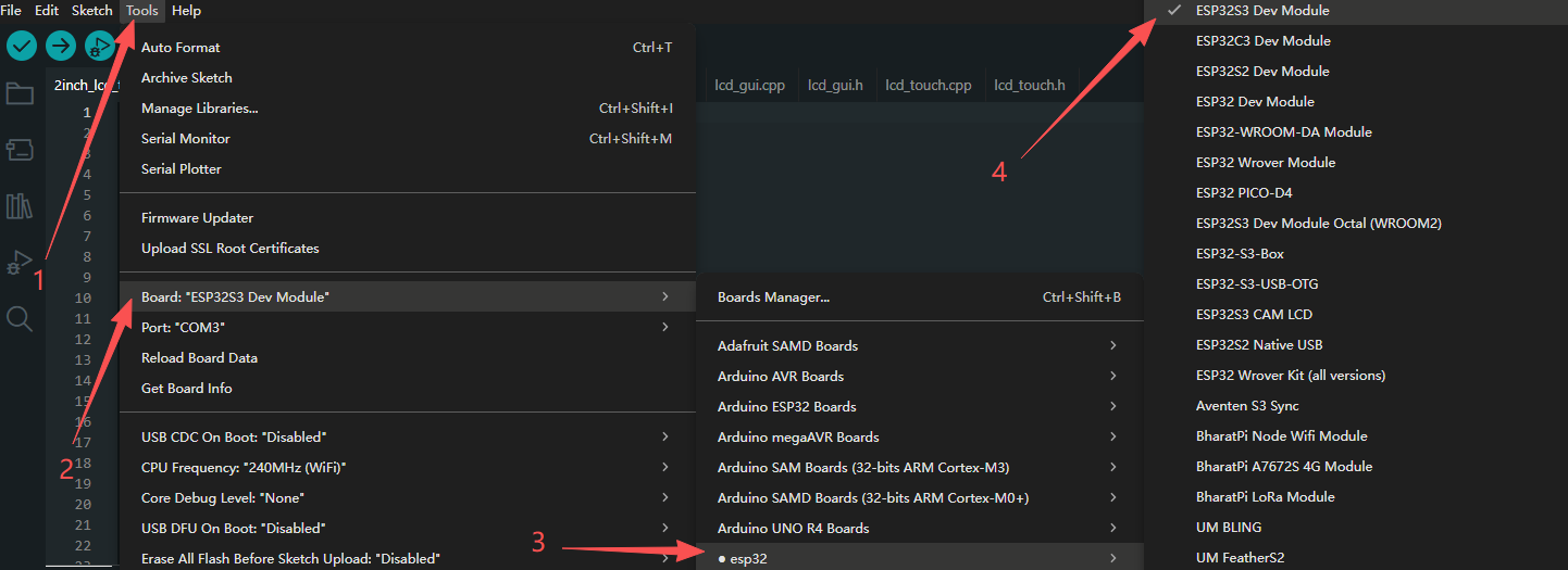
 2.3 ESP32S3 Demo Code
Connect the board to ESP32S3 according to the following table:
| Pin Name | ESP32S3 | Description |
|---|---|---|
| VCC | 3V3 | Power Positive |
| GND | GND | Power Ground |
| SCK | IO48 | SPI Clock Signal |
| MOSI | IO47 | SPI Data Output |
| LCD_RST | IO12 | LCD Reset Signal |
| LCD_DC | IO13 | LCD Data/Command Select |
| LCD_CS | IO14 | LCD Chip Select |
| LCD_BL | IO38 | LCD Backlight Control |
| TP_RST | IO6 | Touch Reset Signal |
| TP_SCL | IO4 | Touch I2C Clock |
| TP_SDA | IO5 | Touch I2C Data |
| TP_INT | IO7 | Touch Interrupt |
2.4 Raspberry Pi Demo Code
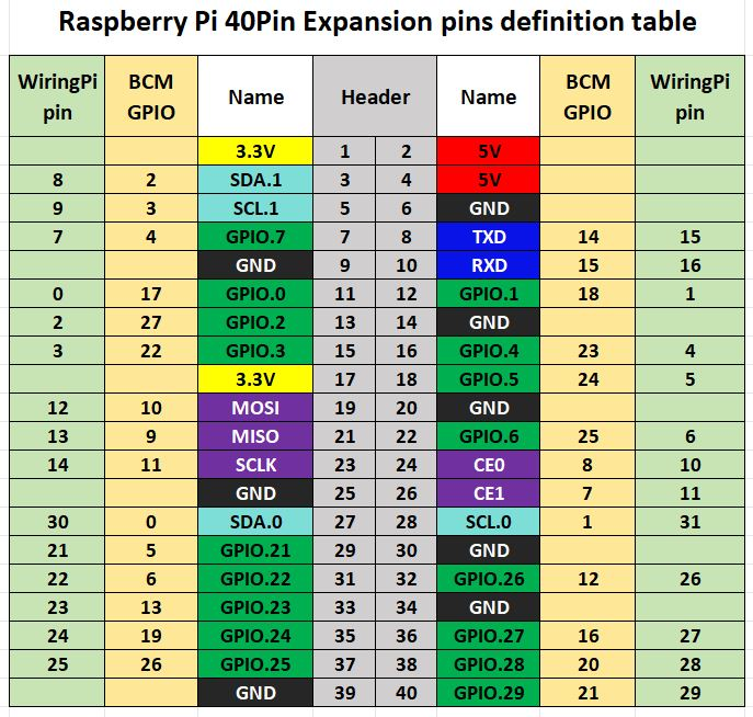
For the Raspberry Pi Bullseye system, the example program uses wiringPi pin numbering; for the Bookworm system, it uses BCM pin numbering. Connect the board to the Raspberry Pi according to the following table.
| Pin Name | Raspberry Pi (BCM) | Description |
|---|---|---|
| VCC | 3V3 | Power Positive |
| GND | GND | Power Ground |
| SCK | D11 | SPI Clock Signal |
| MOSI | D10 | SPI Data Output |
| LCD_RST | D22 | LCD Reset Signal |
| LCD_DC | D25 | LCD Data/Command Select |
| LCD_CS | D8 | LCD Chip Select |
| LCD_BL | D24 | LCD Backlight Control |
| TP_RST | D27 | Touch Reset Signal |
| TP_SCL | D3 | Touch I2C Clock |
| TP_SDA | D2 | Touch I2C Data |
| TP_INT | D17 | Touch Interrupt |
2.4.1 Installing WiringPi Library
sudo raspi-config
sudo apt-get install wiringpi
Wget https://project-downloads.drogon.net/wiringpi-latest.deb
sudo dpkg -i wiringpi-latest.deb
gpio -v # If version 2.52 appears, the installation is successful
For the Bullseye branch system, use the following commands:
git clone https://github.com/WiringPi/WiringPi
cd WiringPi
./build
gpio -v
# Running gpio -v will show version 2.70; if it does not appear, the installation has failed.
# If you encounter the error "ImportError: No module named 'wiringpi'" when running the Python version of the example program, please run the following command:
# For Python 2.x
pip install wiringpiFor Python 3.x
pip3 install wiringpigit clone --recursive http://github.com/WiringPi/WiringPi-Python.gitNote: The --recursive option can automatically pull submodules; otherwise, you need to download them manually. Enter the newly downloaded WiringPi-Python folder and run the following commands to compile and install:
# For Python 2.x
sudo python setup.py install# For Python 3.x
sudo python3 setup.py installIf you see the following error: # Run "sudo apt install swig" to install swig, then compile and install againsudo apt install swigsudo python3 setup.py install
2.4.2 Installing LGPIO Library
For the Bookworm system, the example program uses the lgpio library. The installation commands are as follows:
wget https://github.com/joan2937/lg/archive/master.zip
unzip master.zip
cd lg-master
make
sudo make install
2.4.3 Running Python Demo
Enter the Python example directory:
cd /home/pi/2inch lcd display demo/raspberry pi/lgpio/pythonor
cd /home/pi/2inch lcd display demo/raspberry pi/wiringpi/pythonsudo python3 demo.pycd /home/pi/2inch lcd display demo/raspberry pi/wiringpi/cRun:
sudo make clean
sudo mkae
sudo /.main
III. Related Links
SCH
Proture