
I Product Overview
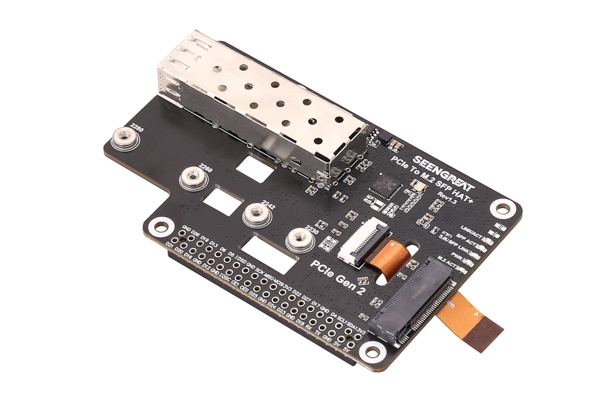
Raspberry Pi 5 PCIe to M.2 & SFP Gigabit OpticalAdapter Board Compatible with 2280/2260/2242/2230 Size NVMe SSDs, HAT+ Standard
This is a multi-functional PCIe HAT+ expansion board specially designed for Raspberry Pi 5. Equipped with the ASM1182e PCIe expansion chip, it splits the single PCIe interface of Raspberry Pi 5 into two independent PCIe lanes, which are used for connecting M.2 NVMe SSD and Gigabit Ethernet controller respectively, enabling dual functions of M.2 solid-state drive expansion and Gigabit SFP fiber communication.
It supports M.2 NVMe SSDs in multiple form factors including 2280, 2260, 2242 and 2230. It is widely applicable for system boot drives, data storage, lightweight NAS, edge computing gateways, industrial communication and long-distance network transmission scenarios.
For network connection, it adopts RTL8111H + RTL8213B solution, and supports Gigabit fiber network communication via standard SFP port with optical modules installed. Onboard EEPROM chip and 2×20Pin header are designed in compliance with Raspberry Pi HAT+ specifications, allowing Raspberry Pi 5 to automatically recognize the board and complete relevant configurations easily.
II Features
- Supports simultaneous M.2 NVMe SSD expansion and Gigabit SFP fiber network communication via PCIe interface.
- Equipped with standard onboard SFP port for Gigabit fiber network connection.
- Compatible with NVMe SSDs in 2230, 2242, 2260 and 2280 form factors.
- Compliant with HAT+ standard, enabling automatic detection by Raspberry Pi software and firmware.
- Built-in LED status indicator.
III Specifications
Compatible Motherboard: | Raspberry Pi 5 |
PCIe Speed | PCIe x1 Gen2.0 |
PCIe Switch Chip | ASM1182e |
Network Interface | Standard SFP Optical Port |
Network Control Chip | RTL8111H |
Fiber Conversion Chip | RTL8213B |
M.2 SSD Form Factor | 2230/2242/2260/2280 |
Power Supply Voltage | 5V |
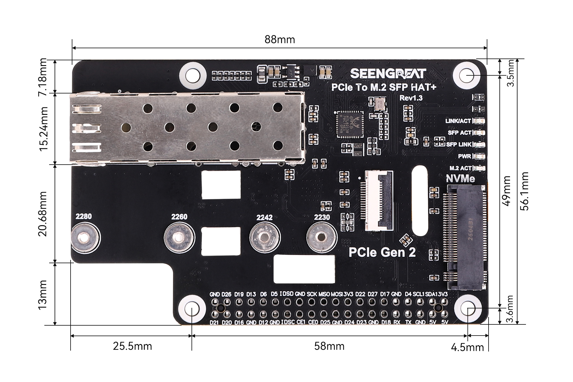
Product Dimensions | 88mm (Length) x 56.1mm (Width) |
IV Usage
4.1. Resource Overview
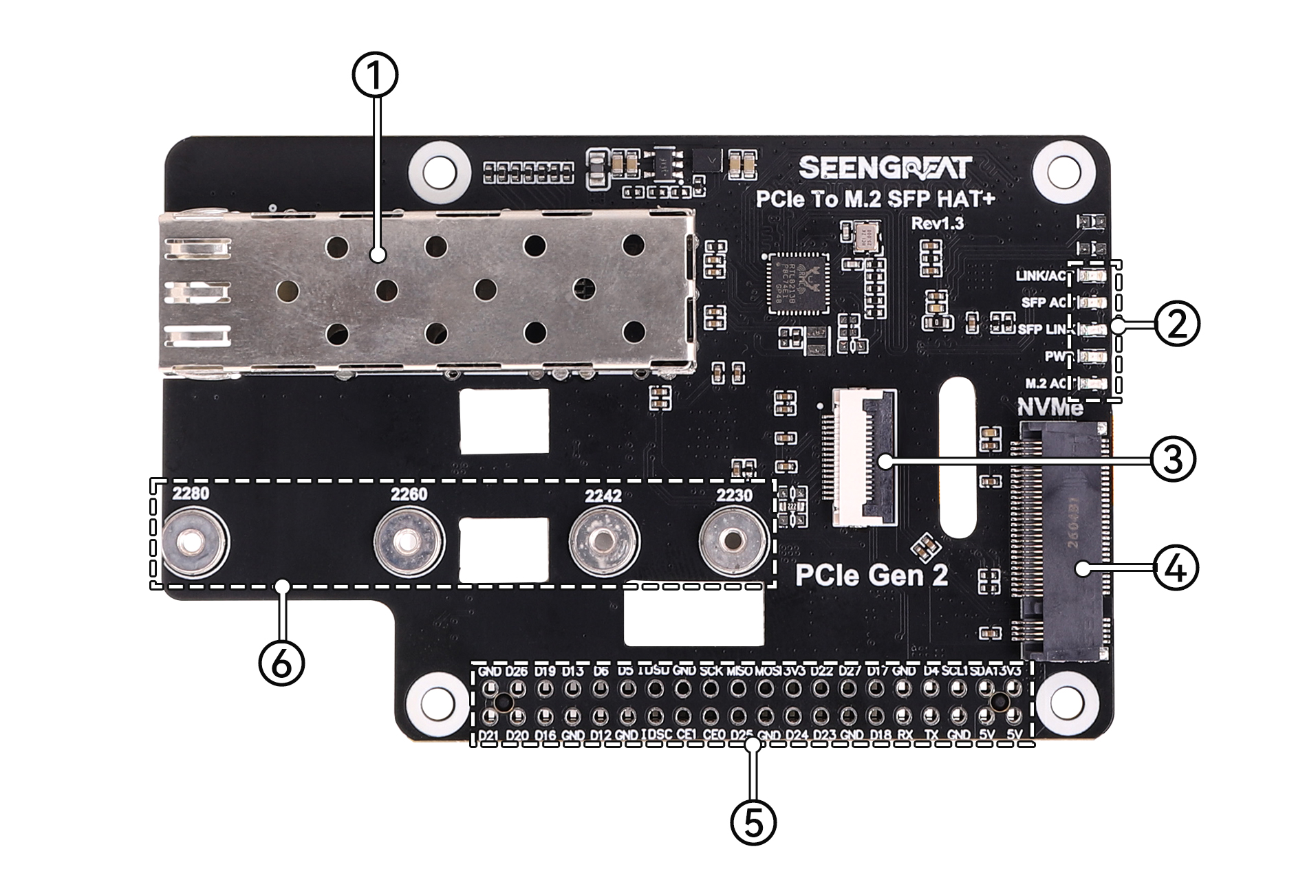
Figure 4-1 PCIe To M.2 SFP HAT+ Resource Overview
① SFP Gigabit Optical Port Connector
② Network Status LED Indicator
③ PCIe 16P FPC Connector
④ NVMe M-Key Slot
⑤ Raspberry Pi 40-Pin Expansion Header Through-Hole Female Header
⑥ NVMe SSD Mounting Holes
4.2. Installation Instructions
Note: This product does not include optical modules or optical fibers. Users shall select and purchase compatible optical modules and optical fibers according to actual application scenarios. Optical modules are generally used in pairs.
Common Matching Examples:
Optical Module | TypeOptical Fiber Type | Description |
1000BASE-SX | Multimode Optical Fiber | Commonly used for short-distance transmission |
1000BASE-LX | Single-mode Optical Fiber | Commonly used for long-distance transmission |
Gigabit BiDi SFP | Single-mode Single-fiber | TX/RX wavelengths must be matched in pairs |
Note: When using BiDi single-fiber modules, the TX/RX wavelengths of the two-end modules must be paired and matched. For example, one end is 1310nm TX / 1550nm RX, and the other end is 1550nm TX / 1310nm RX.
First connect the 16P flexible flat cable to the on-board FPC connector (See ③ in Figure 4-1). Make sure not to reverse the installation direction of the flexible cable (refer to Figure 4-2). Then connect the other end of the flexible cable to the FPC connector (PCIe interface) on the side of Raspberry Pi 5, and finally fix the SSD solid state drive.
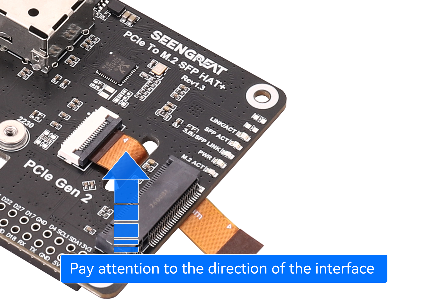
Figure 4-2
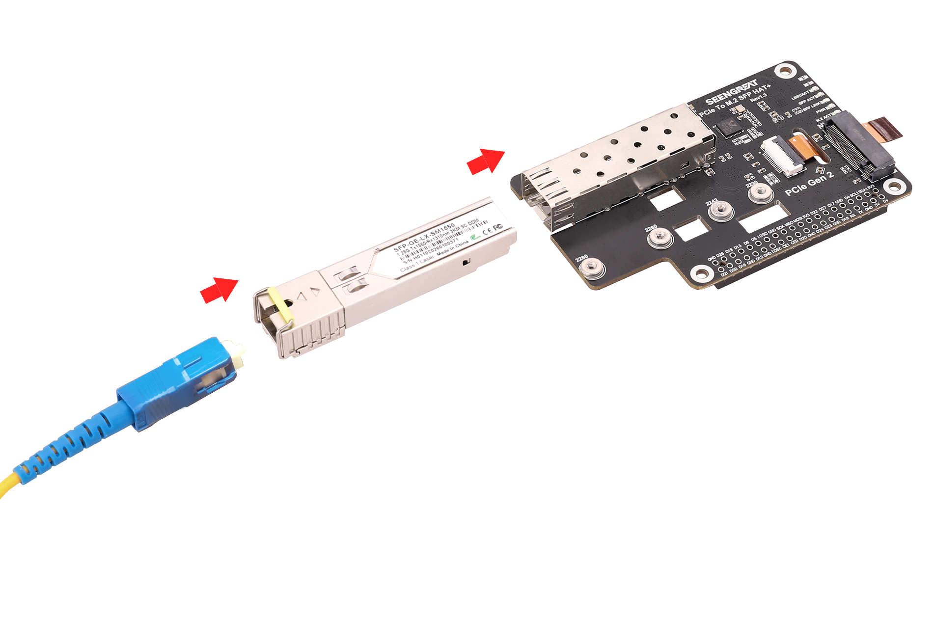
The installation diagram of the SFP optical port is shown in Figure 4-3. Insert the optical fiber into the jack of the optical module, then plug the optical module into the SFP cage on the board.
The product installation and wiring diagram is shown in Figure 4-4.
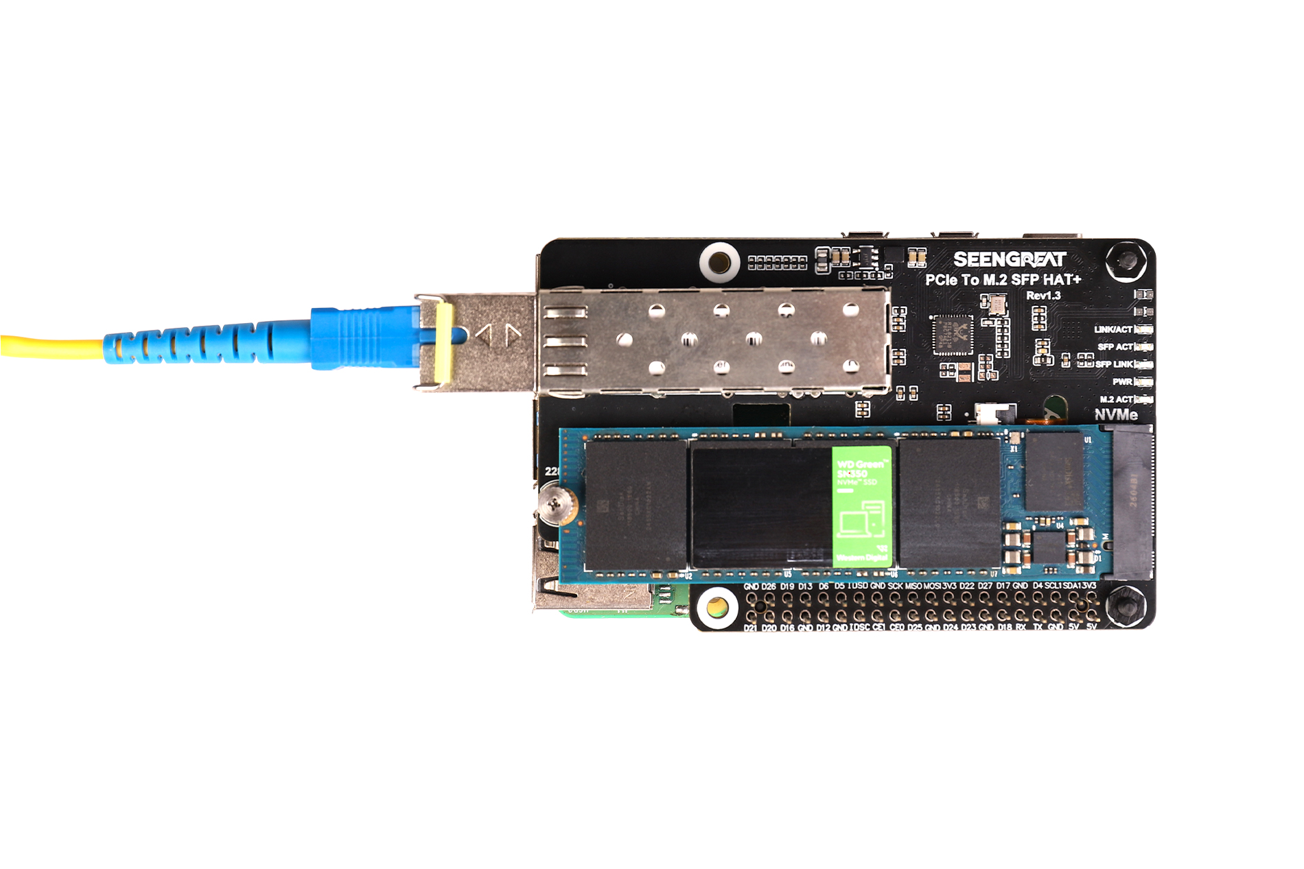
Figure 4-4
4.3. Usage Instructions
Note: This module only supports PCIe Gen 2.0 x1.The PCIe interface is enabled by default on Raspberry Pi 5. If the device fails to boot, add the line dtparam=pciex1 to /boot/firmware/config.txt, save the file, then reboot your Raspberry Pi.
4.3.1. Power-On Detection
After powering on, run the lspci command in the terminal. If the output shows entries containing "Non-Volatile memory controller ..." and "RTL8111/8168/8411 ...", it indicates that the SSD (if installed) and the RTL8111H network card have been successfully recognized. The ASM1182e is the detected PCIe bridge chip, as shown in Figure 4-5.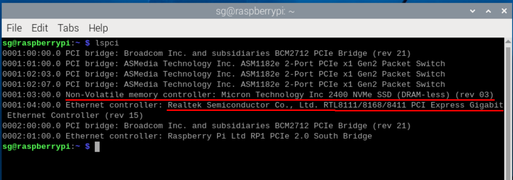
Figure 4-5
4.3.2. SFP Gigabit Network Test
Enter the ifconfig command in the terminal to check the IP address of the network interface, as shown in Figure 4-6 below, where "eth1" is displayed (the IP address may vary in different environments):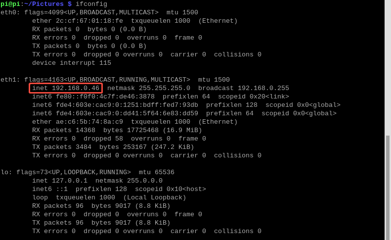
Figure 4-6
Users can use theping command to test network connectivity, and can also replace the domain name in the command with another one.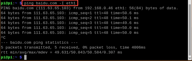
4.3.3. SSD Test
After the user has correctly installed the hard drive and successfully recognized it (refer to the previous lspci command), the following tests can be performed.
1. Partitioning
Thelsblk command can be used to view disk information, as shown in the following figure: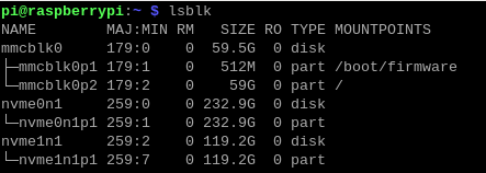
The fdisk command is a partitioning tool. For example, the command sudo fdisk /dev/nvme0n1 performs partitioning operations on the disk device nvme0n1. Do not add p1, p2, etc., as those represent partitions within the disk. The usage of the fdisk tool is as follows:
- p
– Print the partition table- d
– Delete a partition- n
– Create a new partition- q
– Quit without saving- m
– Print the menu- w
– Write changes and quit- t
– Modify the partition type ID
To add a partition, simply execute n. Finally, use w to save changes and exit.
2. Formatting
Enter the sudo mkfs. command, then press the Tab key. You will see many different suffixes — these suffixes represent the file system formats you can use for formatting.
For example, the following command formats the partition nvme0n1p1 as ext4:
sudo mkfs.ext4 /dev/nvme0n1p1After "done" appears, the formatting is complete.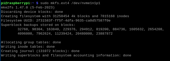
3. Mounting
Create a mount point in the current directory:
sudo mkdir sg2nvme0n1p1 device to the sg2 directory:
sudo mount /dev/nvme0n1p1 ./sg2df -h4. Read/Write Test
Use the cd sg2 command to enter the mounted disk directory, then run the following command to drop the memory cache:
sudo sh -c "sync && echo 3 > /proc/sys/vm/drop_caches"Command to write data to the SSD:
sudo dd if=/dev/zero of=./testfile count=2000 bs=1Msudo dd if=./testfile of=/dev/zero count=2000 bs=1M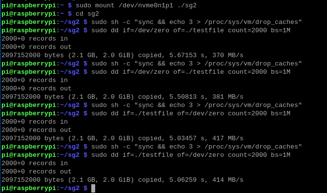
Note: Different SSDs and test environments may result in varying speeds.
5. System Boot
Method 1:
1. Ensure your Raspberry Pi system is the latest version (Bookworm or newer). Enter the following command to update the firmware of the Raspberry Pi 5:sudo apt update && sudo apt upgrade -y
sudo rpi-eeprom-update -a
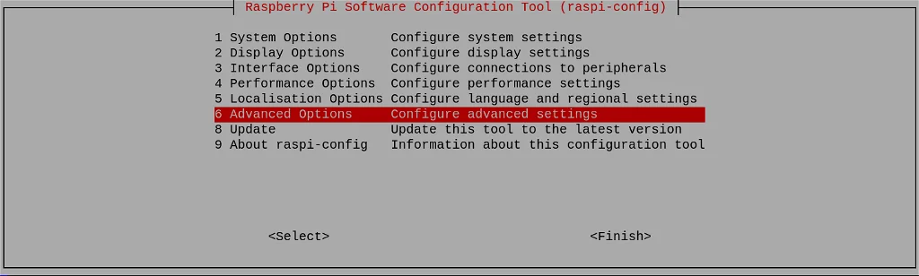
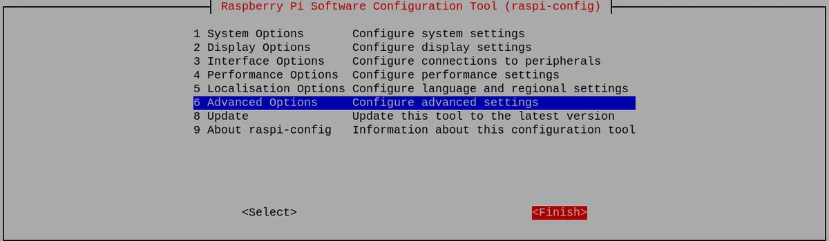
sudo raspi-configAdvanced Options->press Enter:
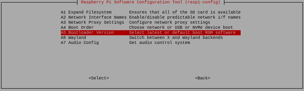
Bootloader Version->press Enter:
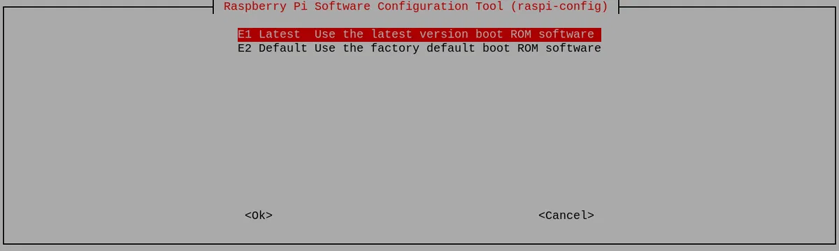
Latest->press Enter
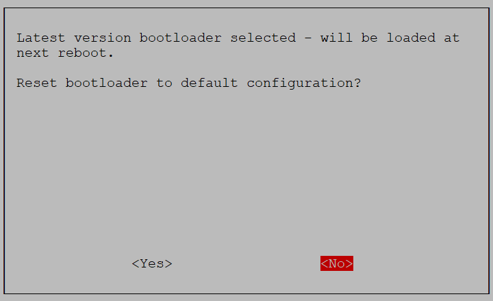
Select No here - you want the latest bootloader.
And exit from the tool by selecting Finish:
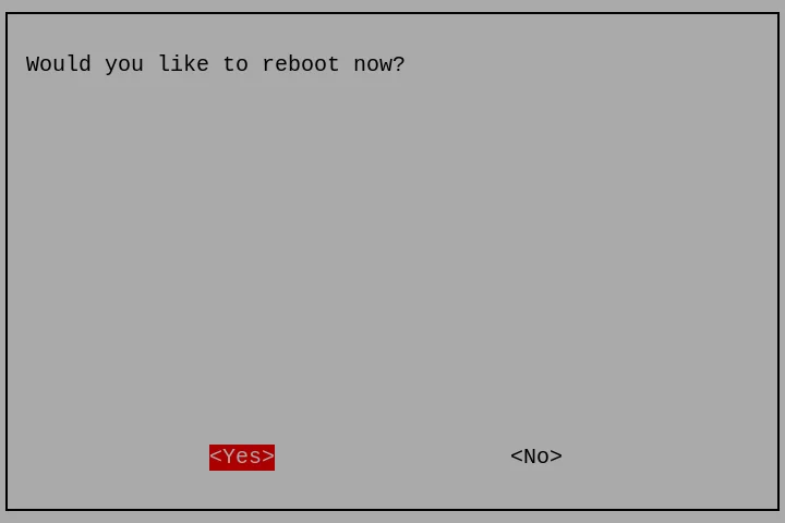
If asked to reboot, select Yes.
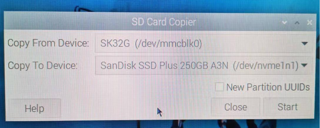
Step 2:Cick Applications =>Accessories =>SD Card Copier on the main screen, run the SD Card Copier program, and copy the OS to the NVME SSD as shown in the figure below.
Copy From Device: Select the source device to copy from.
Copy To Device: Select the destination device to copy to.
If you need to copy the system from the SD card to the NVMe SSD, generally select the SD card in the Copy From Device field and select the NVMe SSD in the Copy To Device field, as shown in the figure below:
If your SD card slot is easily accessible, you can shut down the Pi, remove the SD card. If everything is working properly, it should automatically boot from the NVMe drive the next time you power on. However, if you want to keep the SD card in place while still booting from the NVMe drive, you will need to change the boot order.
Enter the following command:
sudo raspi-configselect Advanced Options and press Enter:
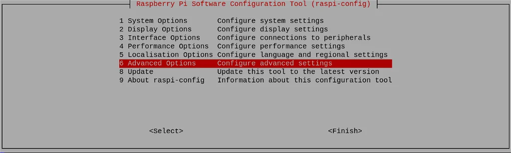
select Boot Order and press Enter:
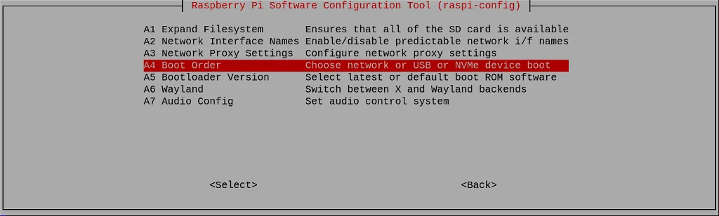
Choose NVMe/USB Boot and press Enter:
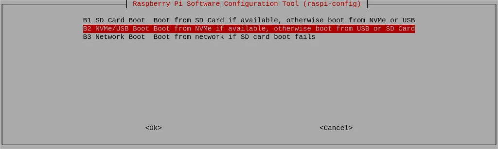
Configuration will be confirmed. Press Enter:
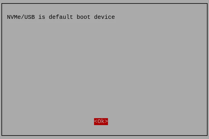
Return to the first screen by selecting Back or pressing the Esc key. Then navigate to Finish using the right cursor key.
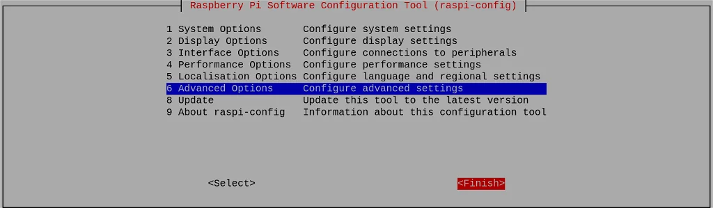
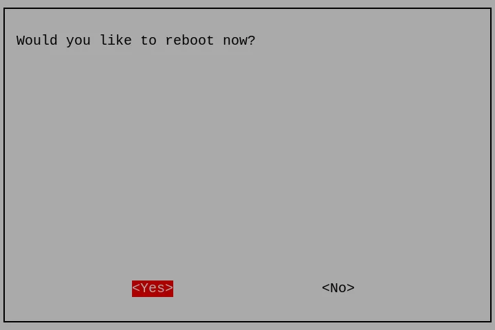
You will be asked whether you want to reboot now. Click Yes:
Method 2:
For system flashing, please refer to the SD Card Copier in Method 1 or use Raspberry Pi Imager.
After booting the Raspberry Pi from the SD card system, modify the bootloader configuration by changing the BOOT_ORDER. Enter the following command in the terminal:
sudo rpi-eeprom-config --editNVME_CONTROLLER=1BOOT_ORDER=0xf41BOOT_ORDER=0xf416For more details, please refer to the BOOT_ORDER documentation.
If you want to give priority to SD card booting, you can change it to:
BOOT_ORDER=0xf4614.4. Related Instructions
1. Status LEDs:
- LINK/ACT (Yellow LED): Indicates the network status of the RTL8111H chip. It flashes when connected and stays solid on when disconnected.
- SFP LINK (Green LED): Lights up when the SFP signal link is established. It stays solid on when connected and turns off when disconnected.
- SFP ACT (Yellow LED): Indicates the SFP data communication status. It flashes during data transmission and turns off when idle.
- PWR (Red LED): Board power indicator. It stays constantly on.
- M.2 ACT (Green LED): Indicates the activity status of the M.2 SSD. It flashes when data is being read from or written to the SSD.
Ⅴ Appendixes
5.1 Precautions and Maintenance of Products
5.1.1 Precautions
- Please do not remove or insert the modules while it is running!
- Please follow all warnings and guidance information marked on the product.
- Please keep this product dry.If it is splashed or soaked by any liquid accidentally, please power off immediately and dry thoroughly.
- Please pay attention to the ventilation and heat dissipation in the environment of running the product to avoid the damage of components by high temperature.
- Please do not use or store the product in dusty or dirty environment.
- Please do not use the product in alternating environment between hot and cold to avoid condensation damage to the components of the product.
- Please do not handle the product roughly. Falling, knocking or violent shaking may damage the circuit and components.
- Please do not clean this product with organic solvents or corrosive liquids.
- Please do not repair or disassemble our products by yourself. If the products break down, please contact us for maintenance in time.Unauthorized repair may damage the product,so the resulting damage will not be covered by warranty.