I. Introduction
1.1 Product Overview
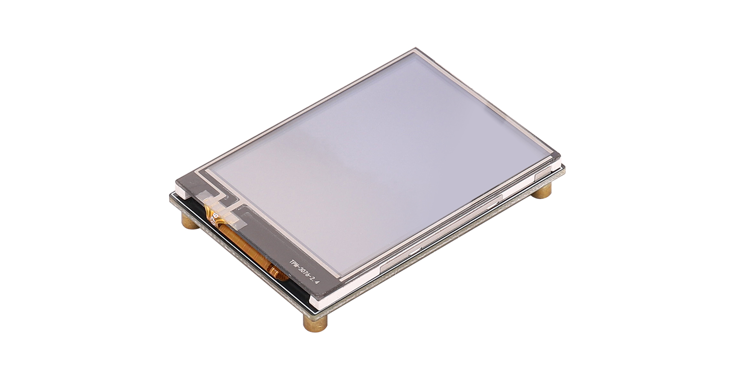
This 2.4-inch resistive touch screen integrates display and touch functions. It employs the ILI9431 display driver chip and the XPT2046 touch controller chip, ensuring stable and reliable touch input while maintaining excellent display quality. The board's form factor matches the screen's dimensions, resulting in a compact structure ideal for integration into small devices with space constraints. The control interface uses a 1.25mm pitch 12-pin connector, facilitating system cabling and modular assembly, balancing connection stability with manufacturing convenience, providing an intuitive display and operational experience for devices.
1.2 Product Features
- 2.4-inch LCD resistive touch screen, 320×240 resolution
- Resistive touch controller chip XPT2046 enables touch interaction, allowing users to input and control directly on the screen
- SPI communication interface
- Built-in ILI9341 controller
1.3 Product Specifications
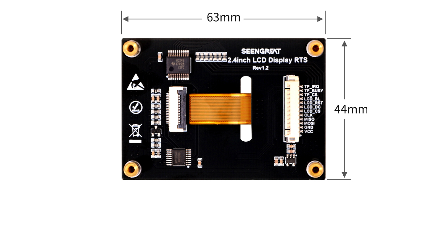
Dimensions | 63mm(Length) ×44mm(width) |
Resolution | 320 × 240 |
Communication Interface | SPI |
Active Area | 48.96mm × 36.72mm |
Display Color | RGB 262K |
Display Driver Chip | ILI9341 |
Touch Controller Chip | XPT2046 |
Supply Voltage | 3.3V / 5V |
1.4 Module Resources
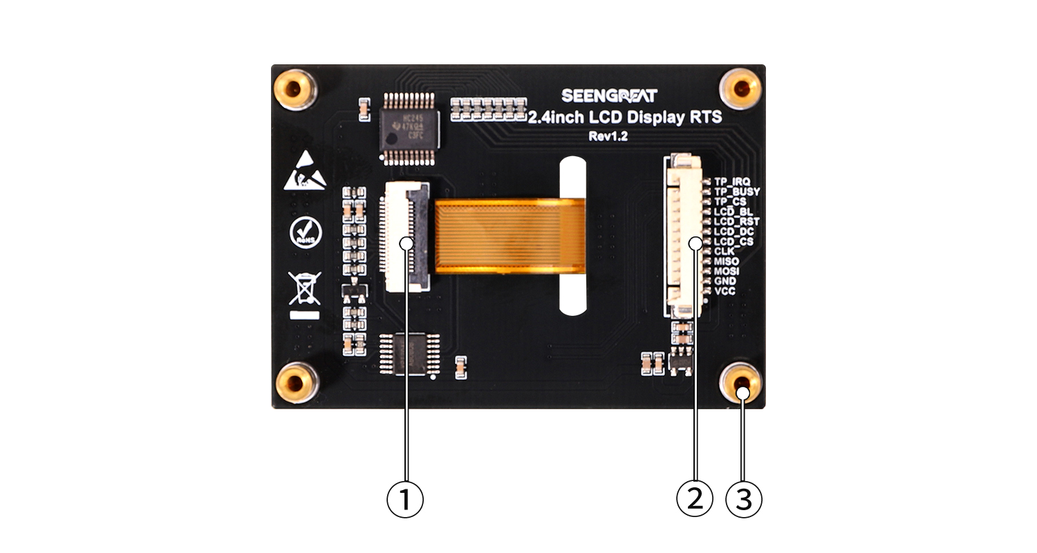
① LCD screen connector
②Control interface: 12-pin 1.25mm pitch connector
③M2.5 SMT brass standoff
I. Usage
2.1 Hardware Description
2.1.1 Interface Definition
Pin Name | Description |
VCC | Power positive |
GND | Power ground |
MOSI | SPI data input |
MISO | SPI data output |
CLK | SPI clock signal |
LCD_CS | LCD chip select |
LCD_DC | LCD data/command select |
LCD_RST | LCD reset signal |
LCD_BL | LCD backlight control |
TP_CS | Touch panel chip select |
TP_BUSY | Touch panel busy signal |
TP_IRQ | Touch panel interrupt |
2.2 Arduino Demo Code
2.2.1 Connecting to Arduino UNO
Connect the module to an Arduino UNO according to the table below.
Module Pin | Arduino UNO | Description |
5V | 5V | Power Positive |
GND | GND | Power Ground |
CLK | D13 | SPI Clock Signal |
MISO | D12 | SPI Data Output |
MOSI | D11 | SPI Data Input |
LCD_CS | D10 | LCD Chip Select |
LCD_BL | D9 | LCD Backlight Control |
LCD_DC | D8 | LCD Data/Command Select |
LCD_RST | D7 | LCD Reset Signal |
TP_CS | D5 | Touch Panel Chip Select |
TP_IRQ | D4 | Touch Panel Interrupt |
TP_BUSY | D3 | Touch Panel Busy Signal |
2.2.2 Program Download
Select the board model and port number as shown in the figures below:
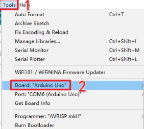
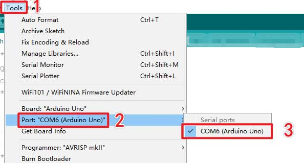 After selection, click Compile, then upload the code to the Arduino UNO.
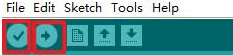 You will see the screen display lines, rectangles, filled blocks, circles, and characters, then enter the touch function display interface, as shown below.
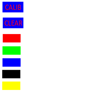
- The "CALIB" button is used for screen calibration. The screen calibration parameters are pre-filled in the
TP_Init()function. Users can update the values oftp_dev.xfacandtp_dev.yfacbased on their own calibration results. After successful calibration, the message "Touch screen calibration confirmed!" will appear on the screen. If calibration fails, the process will restart. If the user does not perform the calibration operation within 10 seconds, the calibration process will automatically exit. - The "Clear" button is used to clear the screen drawing board content, erasing all content drawn by the user on the drawing board.
- The red, green, blue, black, and yellow square buttons are used for the pen color. The default pen color is black. If the user wants to change the color, they can press the corresponding color square button and then draw.