I Product Overview
Supercapacitor UPS Module, 5V Output, 5V-24V Input.
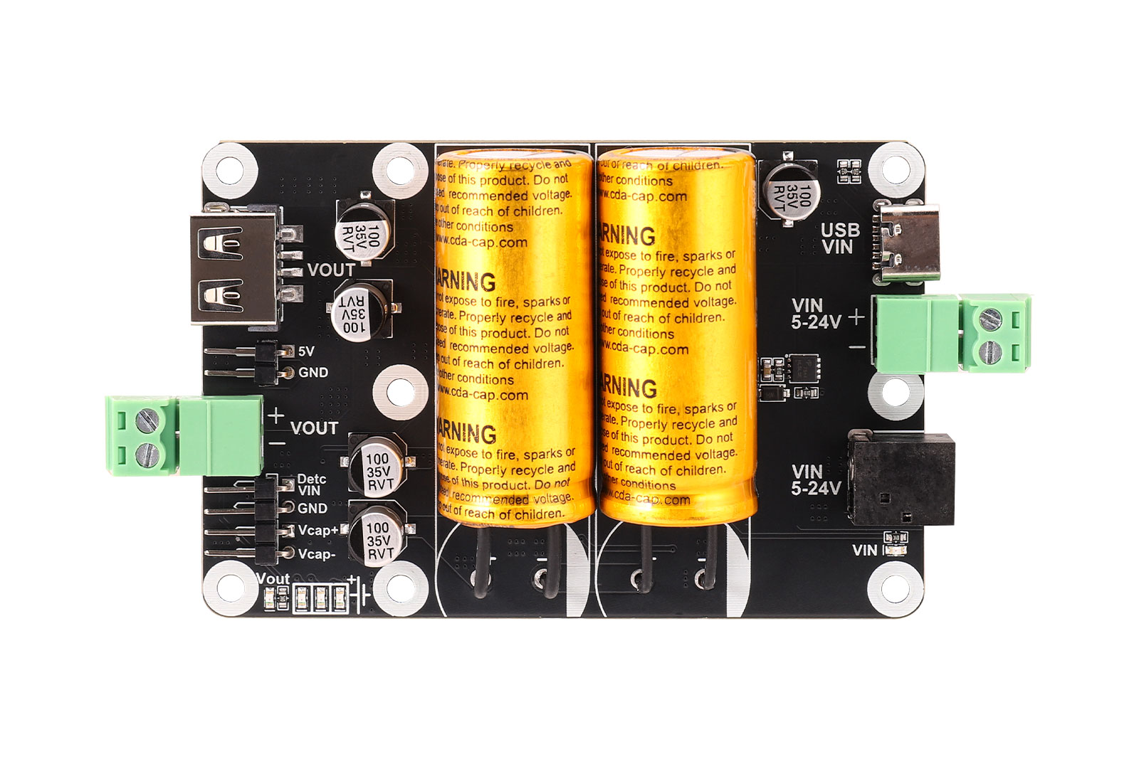
This supercapacitor-based uninterruptible power supply (UPS) module is equipped with two supercapacitors, offering long service life and strong discharge capability. The input supports a wide voltage range of 5V to 24V, with multiple input interfaces including a USB Type-C connector, DC barrel jack, and 2-pin screw terminal, making it suitable for various power supply environments.
The output is regulated at 5V, and multiple output interfaces are provided, including a USB Type-A port, 2-pin screw terminal, and 2-pin header, allowing simultaneous power supply for different peripherals. Several onboard status indicators are available, including an input power indicator, output indicator, and supercapacitor voltage indicators.
When an external power supply is connected and the supercapacitors are fully charged, the board can provide a peak output of 5V/5A. When the external power supply is disconnected, the fully charged supercapacitors can independently provide a stable 5V/3A output.
In the event of external power loss, the module can provide approximately 15 to 110 seconds of backup time, depending on the supercapacitor charge level and load current, giving the system enough buffer time for data saving and safe shutdown.
II Features
• Wide input voltage range: supports 5V-24V input.
• Long cycle life and strong discharge capability with two supercapacitors.
• Peak output up to 5V/5A when external power is connected and the capacitors are fully charged.
• Backup duration of approximately 15-110 seconds during power failure.
• Onboard protections including input reverse-polarity protection and output short-circuit protection.
• Rich status indication with input power LED, output LED, and supercapacitor voltage LEDs.
• Multiple input and output connection options for flexible system integration.
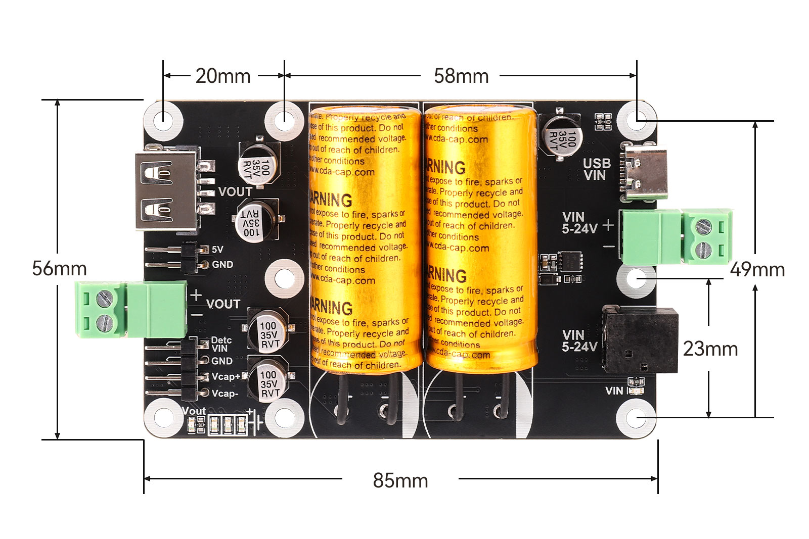
• Compact board size of 85 mm x 56 mm with six M2.5 mounting holes.
III Specifications
Parameter | Description |
Model | SCap UPS Board |
Input Voltage | 5V-24V |
Output Voltage | 5V |
Supercapacitor Bank | 25F (two 2.7V / 50F supercapacitors connected in series) |
Supercapacitor Charging Current | Up to 800mA |
External Power Detection Logic Level | 3.3V |
Discharge Current | 5V/5A output available when external power is connected and the supercapacitors are fully charged |
Standalone Supercapacitor Output | 5V/3A output available when the supercapacitors are fully charged |
Operating Temperature | -40°C to 65°C |
Mounting Hole Diameter | 2.5 mm |
Dimensions | 85 mm x 56 mm |
Module Resources
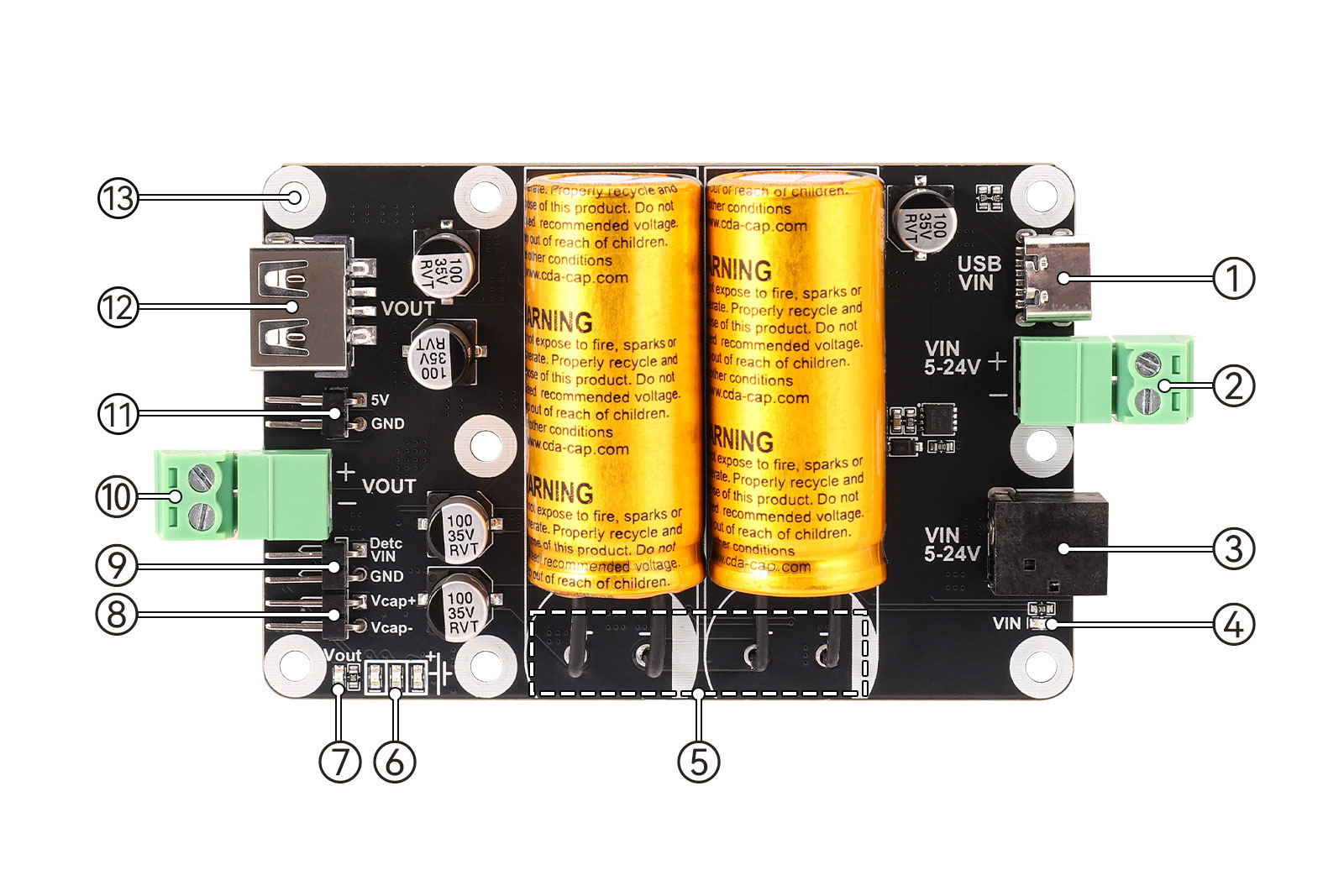
1. Type-C connector: used for connecting a power adapter as the input.
2. 3.81 mm 2-pin screw terminal: input terminal, supports 5V-24V input.
3. DC-044 connector: external power input through a DC plug, supports 5V-24V input.
4. Power input indicator LED: lights up when input power is present; turns off when power is disconnected.
5. Supercapacitors.
6. Supercapacitor voltage status LEDs: provide an approximate indication of the current supercapacitor voltage.
7. Output indicator LED.
8. 2-pin 2.54 mm pitch capacitor measurement header: used to measure the voltage of an individual supercapacitor.
9. 2-pin 2.54 mm pitch input detection header: outputs 3.3V when external power is present and 0V when power is lost.
10. 3.81 mm 2-pin screw terminal: 5V output.
11. 2-pin 2.54 mm pitch header: 5V output.
12. USB Type-A connector: 5V output.
13. M2.5 mounting holes.
IV Usage
4.1 Functional Description
4.1.1. Input Capability
The board supports 5V-24V input. You can connect a power adapter, DC power cable, or similar power source to the board. When power is connected correctly, the VIN indicator will remain on.
If the power is connected incorrectly, such as reversed polarity, poor contact, or similar issues, the VIN indicator will remain off.
4.1.2. Output Capability
The board can provide up to 5V / 5A output. If the output current exceeds 4A for an extended period, additional cooling is recommended to prevent overheating and abnormal operation.
When external power is connected and the supercapacitors are fully charged, the board can provide a peak output of 5V / 5A. After external power is disconnected, the fully charged supercapacitors can independently provide a stable 5V / 3A output.
4.1.3. Supercapacitor Voltage Indicators
The supercapacitor voltage indicators provide an approximate indication of the current capacitor voltage, as shown below:
Capacitor Voltage | LED1 | LED2 | LED3 |
3.074V | ON | OFF | OFF |
4.012V | ON | ON | OFF |
5.133V | ON | ON | ON |
Table 4-1 Supercapacitor Voltage Status LEDs
4.1.4. Output Efficiency Under Different Input Conditions
The output efficiency under different input conditions is shown below:
Input Voltage x Current | Input Power | Output Voltage x Current | Output Power | Conversion Efficiency |
5V x 4.952A | 24.76W | 5.287V x 4A | 21.148W | 85.41% |
9V x 3.166A | 28.494W | 5.281V x 5A | 26.405W | 92.67% |
12V x 2.387A | 28.644W | 5.278V x 5A | 26.39W | 92.13% |
24V x 1.221A | 29.304W | 5.275V x 5A | 26.375W | 90.00% |
Table 4-2 High-Current Output Efficiency Under Different Input Voltages
For all four test conditions above, the board was continuously loaded for 1 hour. The efficiency data is for reference only. Cable losses, device performance variations, and other factors were not excluded during testing. Actual efficiency depends on real application conditions, load level, and environment.
For the temperature rise reference at a 5A load under 12V input to 5V output and 9V input to 5V output conditions, please refer to the corresponding charts in the original wiki documentation.


4.1.5. Discharge Time with Fully Charged Supercapacitors
Reference discharge times with fully charged supercapacitors are shown below:
Load Current | Load Time | Output Voltage Under Load |
0.5A | 116s | 5.030V |
1A | 56s | 4.994V |
1.5A | 36s | 4.967V |
2A | 24s | 4.943V |
3A | 15s | 4.894V |
Table 4-3 Supercapacitor Discharge Time
4.1.6. External Power Loss Detection
Taking Raspberry Pi 4B as an example, use the board's 5V output to power the Raspberry Pi 4B, and connect the DetcVIN pin header to the GPIO18 pin of the Raspberry Pi. The DetcVIN header outputs a 3.3V logic level, and the board's GND should also be connected to the Raspberry Pi's GND pin.
The purpose of the reference wiring diagram in the original wiki is to illustrate the connection method between the board and Raspberry Pi when using the external power loss detection function.
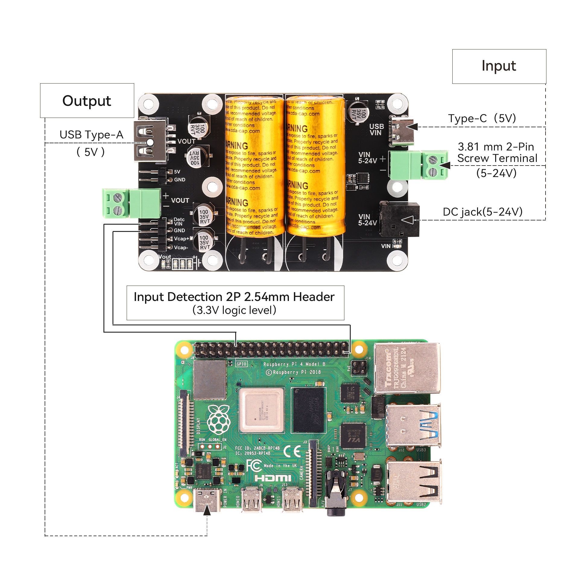
Figure 4-3 Reference Diagram for External Power Failure Detection Connection
First, make sure that the RPi.GPIO library is installed on the Raspberry Pi. It is required for GPIO control. Most Raspberry Pi systems have it installed by default. If not, install it using the following commands:
sudo apt update
sudo apt install python3-rpi.gpio
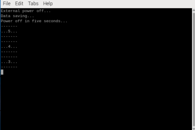
sudo python3 Detc.pyAfter running the code, when the external power is disconnected and the Raspberry Pi is powered only by the supercapacitors, the Raspberry Pi will execute the corresponding data-saving and shutdown commands.
4.1.7. Supercapacitor Charging Time
The maximum charging current of the supercapacitors is approximately 800mA, and it takes about 4 minutes to fully charge the supercapacitors.
4.2 Precautions for Use
• This supercapacitor UPS is designed to provide short-term backup power for devices such as Raspberry Pi during power failure, ensuring data can be saved and reducing damage caused by sudden power loss during storage read/write operations. However, this UPS does not include power path management, so it cannot automatically restart the system after external power is restored.
• Taking the Raspberry Pi platform as an example, after the user application detects external power loss and the system switches to supercapacitor-only power mode, it should complete data saving and execute a software shutdown.
• To wake up the Raspberry Pi again after software shutdown, there are two methods: perform a reset; or wait until the UPS is fully discharged and enters complete power-off mode, after which the Raspberry Pi will start automatically the next time power is applied.
• Please store the board in a dry environment at normal room temperature, and avoid moisture or high temperature.
• Do not use the supercapacitor module in high-temperature or extremely cold environments, otherwise the performance of the supercapacitors may be affected and backup time may be reduced. Also avoid severe impact or contact with sharp objects to prevent damage to the supercapacitors.
FAQ
- Q1: Does the SCap UPS Board support dual power inputs?
A1: No, the SCap UPS Board only supports a single power input.
V Resources
• Product