1. Product Overview
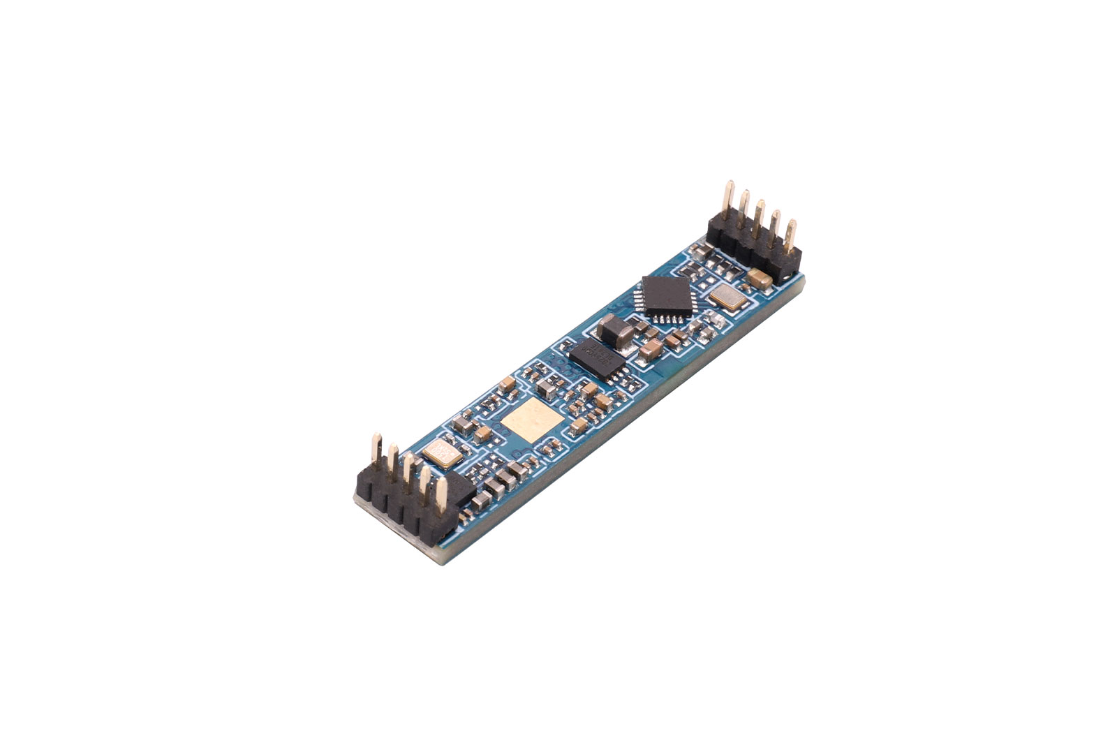
FMCW Microwave Radar Human Presence Sensor Module — LD6004
LD6004 is a radar sensing module developed based on the ADT6101P chip. It integrates a 57–64 GHz RF transceiver system on-chip, a 2T2R AiP packaged antenna, 1MB flash, a radar signal processing unit, and an ARM® Cortex®-M3 core.
Based on FMCW (Frequency-Modulated Continuous Wave) signal processing and radar signal processing algorithms, this module enables highly sensitive human status sensing. It can identify motion, micro-motion, and stationary human presence, and can also provide auxiliary information such as target distance and speed.
With a 2-transmit / 2-receive antenna configuration, the module features a wide beam angle and is suitable for ceiling-mounted installations. It supports GPIO and UART signal outputs, making it flexible for various smart applications and products.
2. Product Features
· Radar detection based on FMCW (frequency-modulated continuous wave) signals
· Supports tracking of up to 3 human targets; outputs target position coordinates x, y, z
· Detects indoor human movement and stationary presence with accurate identification within defined zones; supports sensing-zone partitioning and shielding to reduce interference inside/outside zones
· Supports side-mount mode switching; maximum sensing distance up to 6 m
· Wide detection angle: ±60° horizontal, ±60° pitch
· Standard UART interface; communication protocol provided; UART parameters adjustable to fit different scenarios
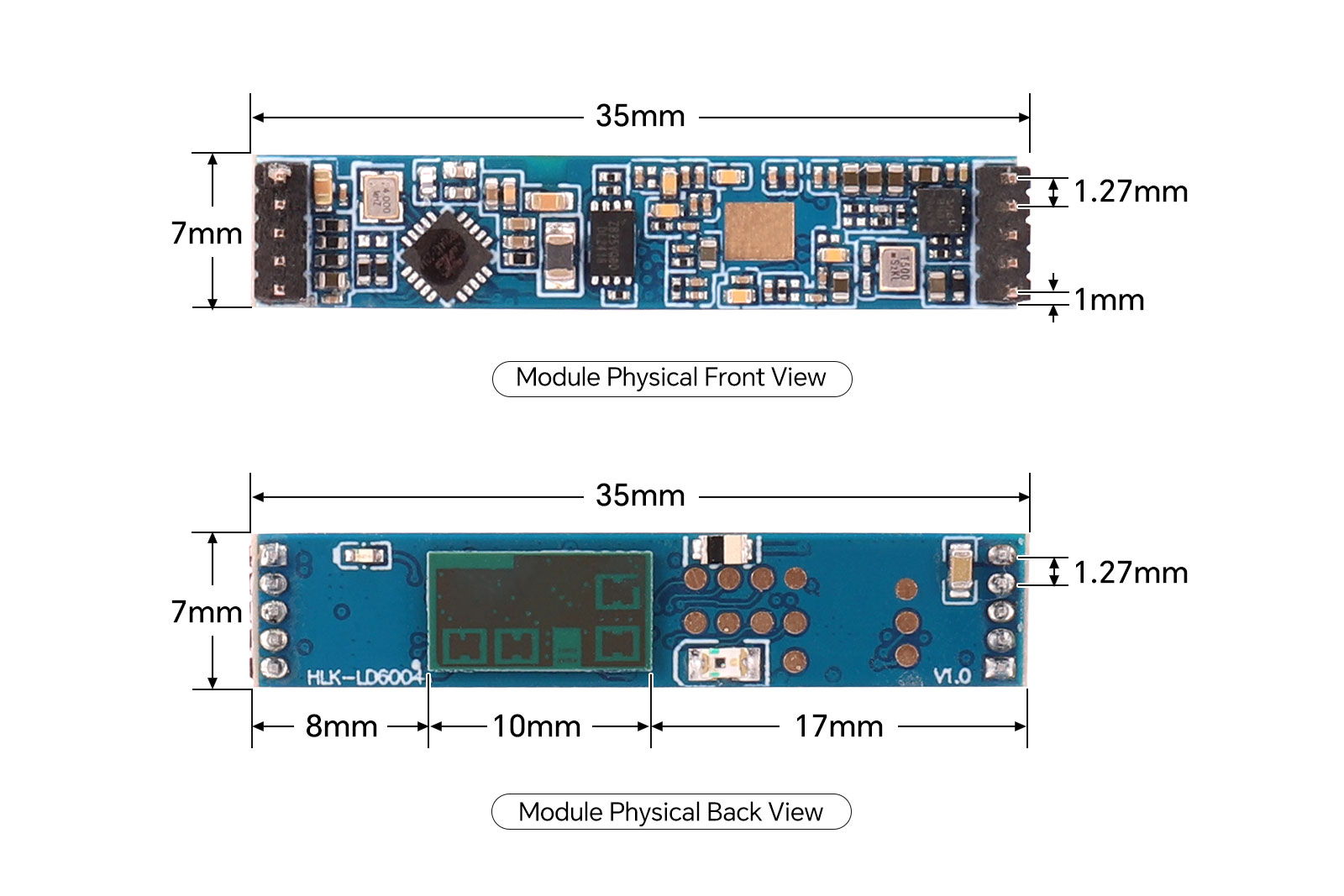
· Compact size: 35x7 mm; supports both pin-header connection and SMT connection
· Not affected by temperature, humidity, noise, airflow, dust, light, and other environmental factors
3. Application Scenarios
- Smart Home Appliance Applications
Based on the detection of the presence or absence of personnel in the room, real-time adjustment of the working mode of home appliances (working, standby, shutdown) to achieve home appliance intelligence.
- Human Body Sensing Light Applications
Perceive the presence of human bodies in the current space and automatically control the switching of lights, such as public scene lighting, office lighting, and various types of sensing lights.
- Smart Home Scene Applications
For places such as homes, hotels, offices, and toilets that require real-time detection of the entry or presence of personnel, so as to realize security, electrical control, personnel monitoring, etc. It can be combined with relevant IoT support platforms to achieve effective applications in relevant places.
4. Specifications
Parameter | Min | Typ | Max | Unit |
Detection targets | .. | .. | 3 | persons |
Distance accuracy | .. | 0.4 | .. | m |
Side-mount sensing distance | 0 | .. | 6 | m |
Recognition accuracy | .. | 95 | .. | % |
Operating voltage (VCC) | 3.1 | 3.3 | 3.5 | V |
Operating current (ICC) | .. | 135 | 600 | mA |
Operating temperature (TOP) | -20 | .. | 85 | °C |
Storage temperature (TST) | -40 | .. | 85 | °C |
Operating frequency | 58 | .. | 64 | GHz |
Transmit power (Pout) | .. | 12 | .. | dBm |
Antenna gain | .. | 4 | 60 | dBi |
Horizontal beam (-3 dB) | -60 | .. | 60 | ° |
Vertical beam (-3 dB) | -60 | .. | .. | ° |
Dimensions
5. Product Usage
5.1 Pin Description
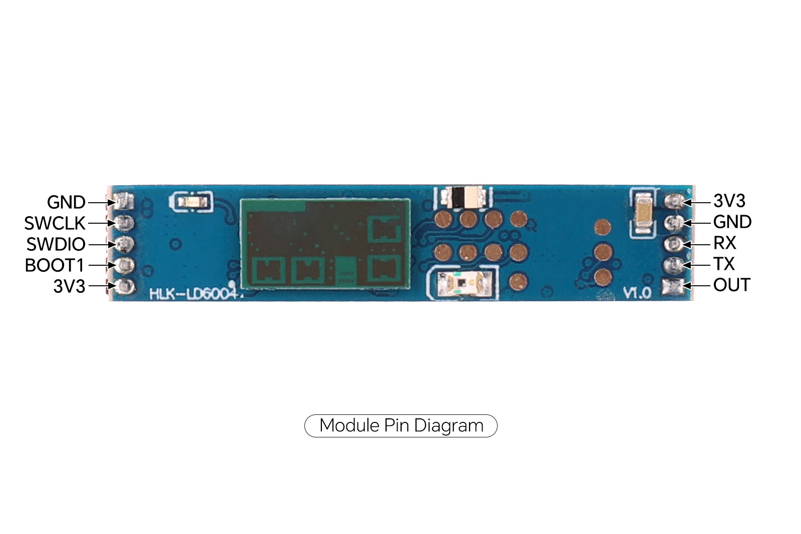
Name | Description | Notes |
3.3V | POWER INPUT 3.3V | .. |
OUT | GPIO_P20 / UART2 TXD | High level when presence detected in zone |
RX0 | GPIO_P01 / UART0_TXD | .. |
TX0 | GPIO_P00 / UART0_TXD | .. |
GND | GND | .. |
3.3V | POWER INPUT 3.3V | .. |
SWCLK | SWD Debug Clock | For debugging |
SWDIO | SWD Debug Signal | For debugging |
GND | GND | .. |
5.2 Module Description
The LD6004 module can directly output the detected target information via the TX2 pin (high level when a person is detected, low level when no one is detected). At the same time, UART0 outputs the detection results according to the specified protocol. The serial port data includes target position, speed and other information, which users can flexibly use according to their specific application scenarios.
The module is powered by 3.3V, and the input power supply must be able to provide more than 1A of current.
The module's IO output voltage is 3.3V.
The serial port communication baud rate is 115200, with no parity check.
Open the human_detection_3d.exe application.
Set the baud rate to 115200.
Select the corresponding serial port for connection.
Click the [Start] button to begin detection.
For more details, please refer to the module product manual in the resources section below.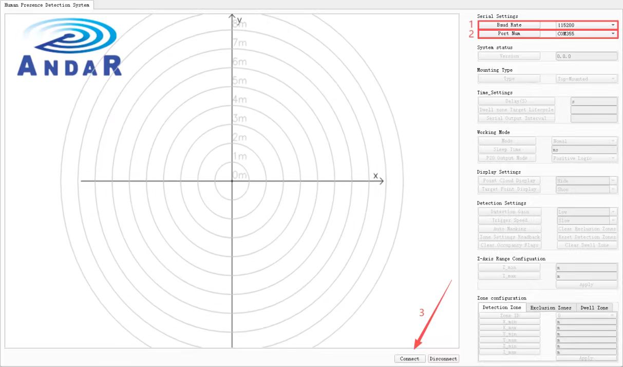
6. Precautions
1. The detection distance of the radar module is highly related to the target RCS and environmental factors. The effective detection distance may vary with the environment and target. Therefore, fluctuations within a certain range are normal.
2. The radar module has strict power supply requirements: input voltage 3.1–3.5 V, ripple ≤ 50 mV, and current capability ≥ 1 A. If using a DC-DC power supply, the switching frequency must be no lower than 2 MHz.