1. Overview
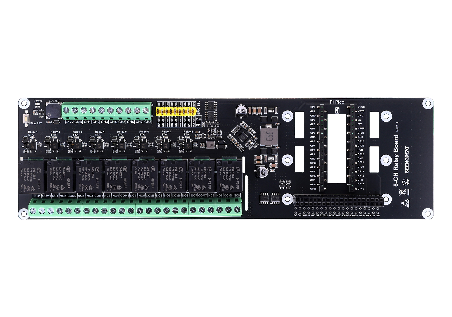
1.1 Product OverviewThis 8-channel relay expansion board is designed for the Raspberry Pi / Raspberry Pi Pico series. It includes a Raspberry Pi 40-pin GPIO header, making it compatible with Raspberry Pi mainboards and suitable for a wide range of Raspberry Pi platforms.
It features eight high-quality relays, each independently controllable, enabling precise ON/OFF switching of connected devices—ideal for home automation, robotics, and other IoT applications. The board includes onboard optocoupler isolation for high-voltage interference protection, helping safeguard your Raspberry Pi. It is flexible and easy to use, with jumper-selectable GPIO to fit different programming needs.
It supports a wide input voltage range (5–12 V) and provides short-circuit protection on the 5 V output, cutting off output promptly in accidental situations to protect your equipment. The board is open-source and includes demo code and technical support for faster issue resolution.
1.2 Product Features
· Wide voltage input: supports 5-12V input
· Isolation protection: optocoupler isolation helps protect the board from high-voltage circuit interference, ensuring stable and safe operation in harsh environments
· Relay load rating: AC 125V/12A, AC 250V/10A, AC 277V/10A, DC 28V/5A
· Clear working status: each relay includes an LED status indicator for real-time visual feedback
· Customizable control: relay control jumpers allow you to assign custom GPIO pins instead of fixed default settings
1.3 Product Specifications
Item | Specification |
Model | 8-CH Relay Board |
Optocoupler | LTV-357T-B-IN |
Input Supply Voltage | 5V-12V |
Relay Trigger Signal | 3.3V / 5V |
Trigger Mode | Active-Low (Low-level trigger) |
Status Indication | Independent LED indicator for each relay channel |
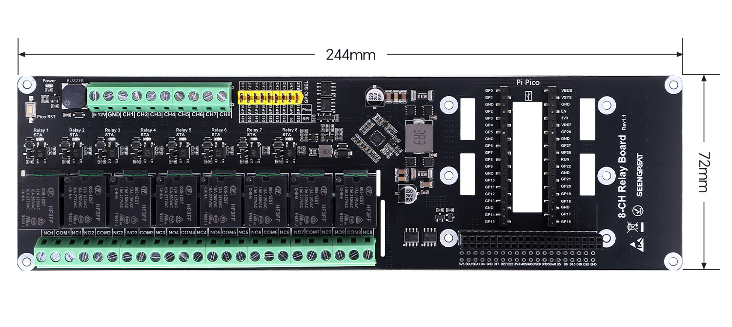
Dimensions | 244 mm (L) x 72 mm (W) |
1.4 Resource Overview
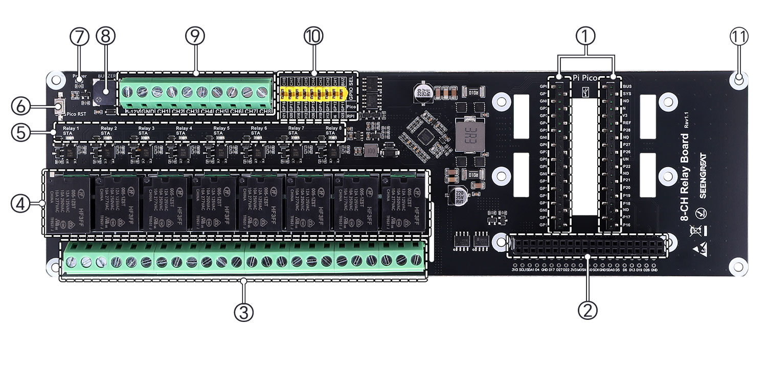
①Raspberry Pi Pico connector
②Raspberry Pi 40-pin connector
③Relay output terminals
④High-quality relays
⑤Relay status LEDs (LED lights when the relay is energized)
⑥Raspberry Pi Pico reset button
⑦Power indicator LED
⑧Buzzer
⑨Power input & relay control signal input terminal
⑩Relay control selection jumpers & buzzer selection jumper
⑪M2.5 mounting holes
2. Usage
2.1 Hardware Interface & Wiring
2.1.1 Raspberry Pi Hardware Connection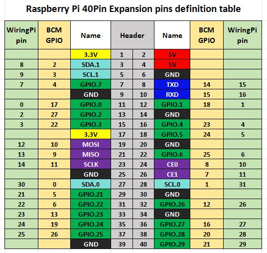
Board Signal | Function | Raspberry Pi (BCM) | wiringPi |
5V | 5V | 5V | 5V |
GND | Ground | GND | GND |
CH1 | Channel 1 | D6 | P22 |
CH2 | Channel 2 | D13 | P23 |
CH3 | Channel 3 | D19 | P24 |
CH4 | Channel 4 | D26 | P25 |
CH5 | Channel 5 | D12 | P26 |
CH6 | Channel 6 | D16 | P27 |
CH7 | Channel 7 | D20 | P28 |
CH8 | Channel 8 | D21 | P29 |
BUZ | Buzzer | D25 | P6 |
Custom control: The onboard relay control can be customized. You may use Dupont wires to connect other GPIO pins to control the relays. Please refer to the Raspberry Pi pinout diagram.
2.1.2 Raspberry Pi Pico Hardware Connection
Board Signal | Function | Raspberry Pi Pico Pin |
5V | 5V | VBUS |
GND | Ground | GND |
CH1 | Channel 1 | GP12 |
CH2 | Channel 2 | GP13 |
CH3 | Channel 3 | GP14 |
CH4 | Channel 4 | GP15 |
CH5 | Channel 5 | GP19 |
CH6 | Channel 6 | GP18 |
CH7 | Channel 7 | GP17 |
CH8 | Channel 8 | GP16 |
BUZ | Buzzer | GP11 |
2.1.3 Relay Wiring Diagram
· NO: Normally Open terminal
· COM: Common terminal
· NC: Normally Closed terminal
2.2 Demo Code on Raspberry Pi
There are two versions of demo code: one for the WiringPi library and one for the lgpio library.
• Bullseye uses WiringPi
• Bookworm uses lgpio
2.2.1 Install WiringPi Library
sudo raspi-config
sudo apt-get install wiringpi
wget https://project-downloads.drogon.net/wiringpi-latest.deb sudo dpkg -i wiringpi-latest.deb
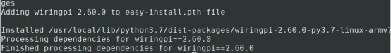
gpio -v # If version 2.52 appears, the installation is successfulFor Bullseye, you can also install/build WiringPi using:
git clone https://github.com/WiringPi/WiringPi cd WiringPi
./build
gpio -v
# You should see version 2.70; otherwise installation failed
If running the Python demo reports: ImportError: No module named 'wiringpi', install the Python module:
# Python 2.x
pip install wiringpi# Python 3.x
pip3 install wiringpiIf installation fails, you can try compiling/installing:
git clone --recursive http://github.com/WitingPi/WiringPi-Python.git# (--recursive pulls submodules automatically)
# Python 2.x
sudo python setup.py install# Python 3.x
sudo python3 setup.py installIf you encounter errors, install swig first:
sudo apt install swig
2.2.2 Install LGPIO Library (for Bookworm)
wget https://github.com/joan2937/lg/archive/master.zip unzip master.zip

cd lg-master

make

sudo make install
2.2.3 Python Demo
cd /home/pi/8-CH-relay/lgpio/python# or
cd /home/pi/8-CH-relay/wiringpi/pythonsudo python3 8-CH-relay.py2.2.4 C Demo
cd /home/pi/8-CH-relay/lgpio/c# or
cd /home/pi/8-CH-relay/wiringpi/csudo make clean
sudo make
sudo ./main2.3 Demo Code on Raspberry Pi Pico
2.3.1 Download and Install Thonny
1. Download Thonny from: https://thonny.org
2. After installing Thonny, connect your computer to the Raspberry Pi Pico using a Micro USB data cable.
3. Insert the Pico into the board in the correct orientation. When the board is powered off, press and hold the BOOTSEL button on the Pico, then connect the Micro USB cable to the computer and the board. Your PC will detect a new drive named RPI-RP2. Drag and drop the demo .uf2 file onto the RPI-RP2 drive to complete setup.
4. Open Thonny -> Run -> Configure Interpreter. Select CircuitPython (generic) and choose the connected serial port.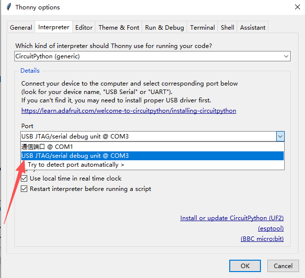
5. Open Shell and the Files window from the View menu to monitor output and debug your code.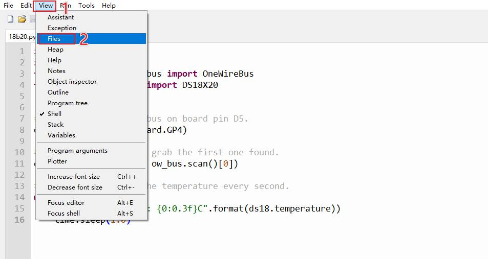
2.3.2 How to Run the Demo Code
1. Relay demo: Open the demo code folder and upload 8-ch.py to the Raspberry Pi Pico. You will see relays energize sequentially starting from channel 1.
2. Buzzer demo: Open the demo code folder and upload beeper.py to the Raspberry Pi Pico. You will hear the onboard buzzer play a short melody.
3. Resource Path
· Product
4. Related Links
(Section reserved)
5. FAQ
(Section reserved)