1. Introduction
1.1 Product Features
- Built on the ESP32-C6FH4, it integrates a high-performance core and rich peripherals, featuring comprehensive functions and easy operation.
- Equipped with the ETA9185 lithium battery charge-discharge chip, it enables efficient charge and discharge management of lithium batteries.
- Comes with a 24P FPC connector, which is compatible with multiple models of e-ink displays.
- Fitted with a ceramic antenna, BOOT & RST buttons and a USB connector, it allows for easy establishment of wireless application systems
- The onboard SD card slot fully meets the needs of data storage
- All GPIO pins are brought out to facilitate the expansion of various peripherals.
This board is suitable for low-power applications such as wearables, electronic shelf labels, portable instruments, and other E-Paper-based products.
1.2 Product Parameters
| Item | Specification |
|---|---|
| Controller | ESP32-C6FH4 |
| Power Supply | USB 5V / 3.7V Li-ion battery |
| E-Paper communication Interface | 3-wire SPI, 4-wire SPI (default) |
| Wireless | 2.4 GHz Wi-Fi 6, Bluetooth 5, Zigbee 3.0, Thread 1.3 |
| BMIC | ETA9185E10 |
| E-Paper Connector | 24P FPC connector(0.5mm pitch) |
| Storage | Micro SD card |
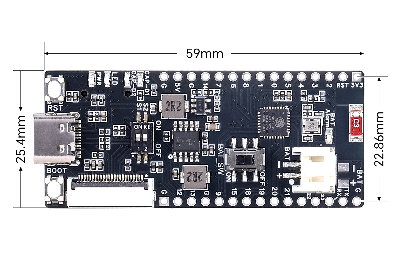
| Module Size | 59 mm (L) × 25.4 mm (W) |
2. Usage
All demos/examples provided for this product are based on 4-wire SPI mode. Therefore, the S1 switch on the front side is set to "ON" by default (4-Line SPI).
S2 is the E-Paper drive resistor selection switch; configure it according to the E-Paper model you use.
2.1 Resource Overview
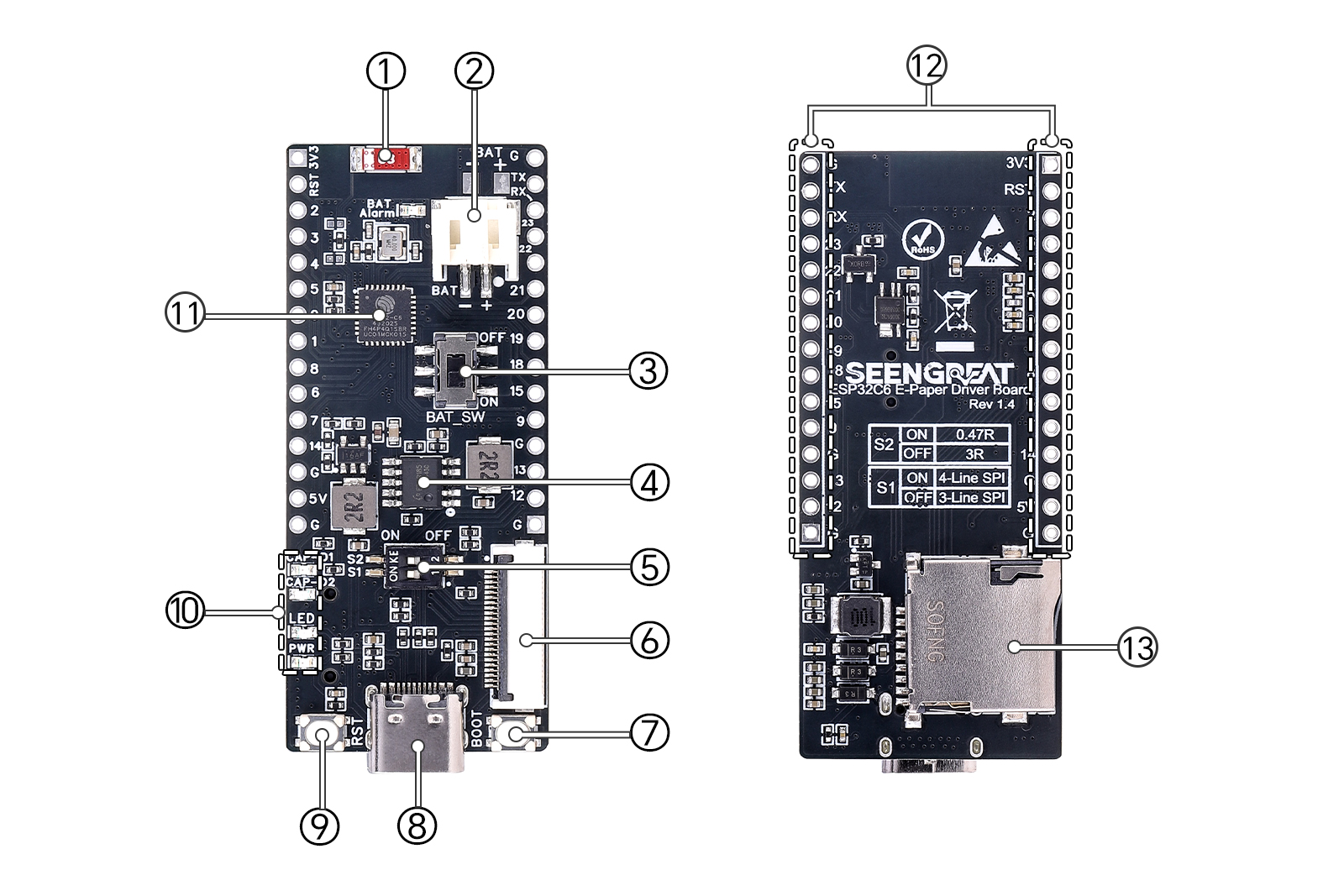
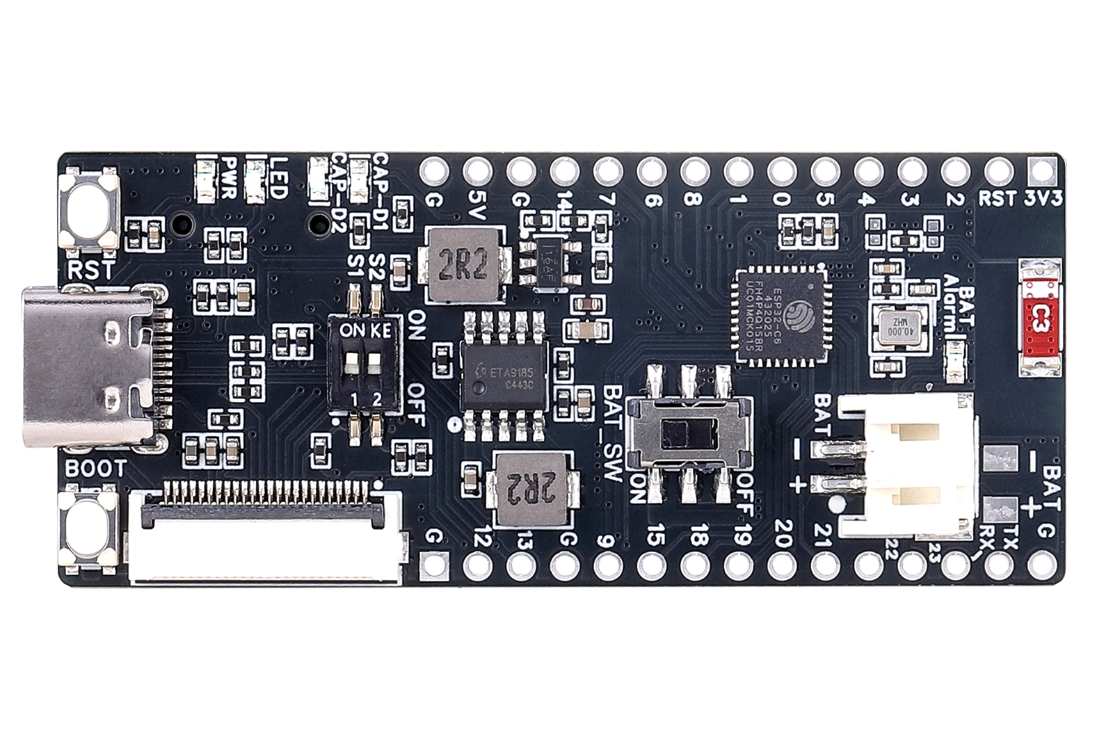
①ESP32 ceramic antenna
②3.7V Li-ion battery connector: PH2.0 2P
③Battery switch
④Battery charge/discharge IC: ETA9185
⑤E-Paper SPI line count & drive resistor configuration switches:
S1 (SPI line count): ON = 4-wire SPI, OFF = 3-wire SPI.
S2 (drive resistor): ON = 0.47 Ω, OFF = 3 Ω
⑥E-Paper connector: for E-Paper displays with 24P control interface
⑦ESP32 BOOT button
⑧USB-C connector: for power supply and firmware uploading
⑨ESP32 RESET button
⑩LEDs:
PWR: power indicator.
LED: user LED.
CAP-D2: High-level Indicator LED for Lithium Battery Capacity.
CAP-D1: Low-level Indicator LED for Lithium Battery Capacity.
⑪ESP32-C6FH4 module
⑫Exposed GPIO Pin Pads
⑬Micro SD card slot
2.2 Hardware Interface Description
2.2.1 Pin Definitions
The wiring definitions between the ESP32-C6FH4 and onboard peripherals are as follows: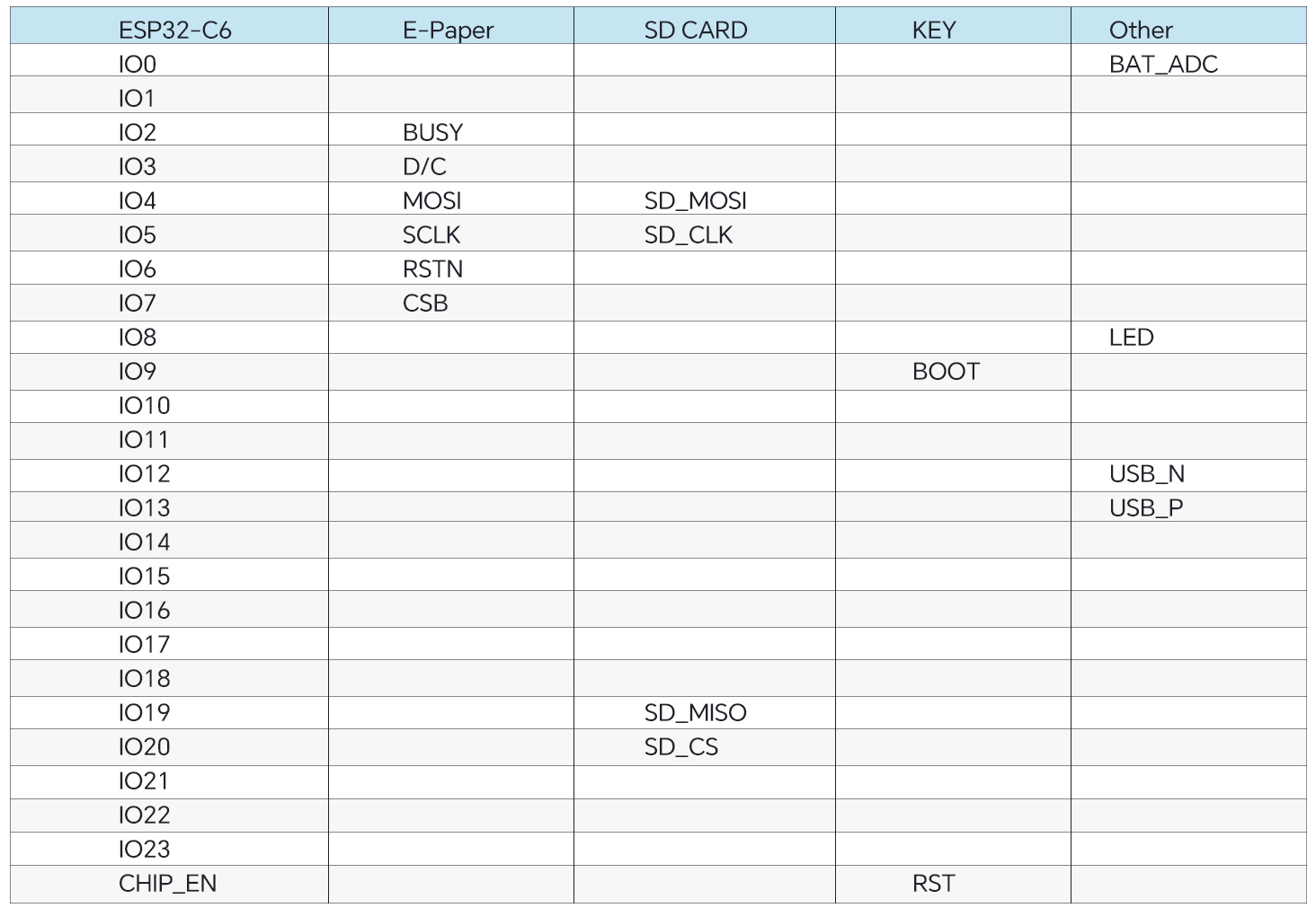
Note: Some IOs are left blank in the original table, indicating no onboard peripheral connection for that pin.
2.2.2 Indicator LEDs
- LED: connected to IO8, user controllable
- PWR: 3.3V power indicator
- CAP_D1 / CAP_D2: battery level indicators
Battery indication states:
State | Battery Voltage Level(C) | CAP_D1(Red) | CAP_D2(Green) |
Charging | C≤25% | 1Hz flash | off |
25%<C≤75% | on | off | |
75%<C | on | 1Hz flash | |
Charging Done | on | on | |
Discharging | 75%<C≤100% | on | on |
3%<C≤75% | on | off | |
C≤3% | 1Hz flash | off |
2.3 Development Environment Setup
Download and install Arduino IDE from the official website, then add the ESP32 board manager URL.
Links (as in the original manual):
https://www.arduino.cc/en/Main/Software
https://dl.espressif.com/dl/package_esp32_index.json
2.4 Demo / Example Usage
Note:
If you do not insert an SD card into the board during use, please comment out the SD card-related content in the demo code. For example, when using the 7.5-inch black-and-white e-paper display, you need to comment out lines 81 and 82 (sd_card_init(); and sd_card_deinit();) in the epd_7inch5_bw.ino file; otherwise, the display may not work properly.
- Open the corresponding demo project in Arduino IDE according to your E-Paper model.
- In Tools → Board, select ESP32C6 Dev Module.
- In Tools → Port, select COMxx (ESP32 family Device) (the port number may differ on different PCs).
- Click Verify, and then Upload after verification passes.
- Observe the E-Paper display output.
The example code includes a Wi-Fi connection test. You may modify ssid and password in the code to match your Wi-Fi credentials.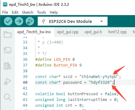
Supported E-Paper Models (continuously updated)
Model | Description | S2 Resistor Switch |
2.9inch E-paper | 296 x 128, Black and white | ON |
7.5inch E-paper Display | 800x480, Black and White | ON |
7.5inch E-Paper RBW | 800x480, Red, Black and White | ON |
2.5 Image Preparation & Bitmap Conversion
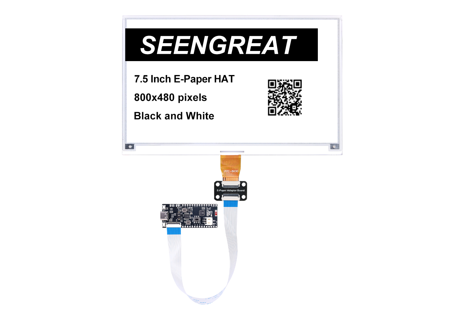
The following uses a 7.5" B/W E-Paper (800×480) as an example. For other models, refer to the corresponding E-Paper Wiki.
2.5.1 Image Preparation
Convert the image you want to display into a pure black-and-white image with 800×480 resolution (grayscale not supported). Save as BMP or JPG (BMP recommended).
2.5.2 Bitmap Conversion (Image to C Array)
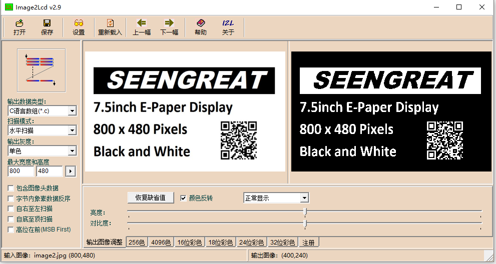
You can use image2lcd to generate the bitmap array (the software is included in the provided package).
Recommended settings:
- Open the image to be converted
- Output data type: C language array (*.c)
- Scan mode: Horizontal scan
- Output grayscale: Monochrome
- Max width/height: set to 800 and 480 (confirm with the arrow button)
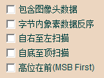
- The 5 options indicated in the figure should all be unchecked
- Color invert: select based on your needs
- Click Save to export a ".c" file. For a pure B/W 800×480 image, the generated array size is 48,000 bytes
- Replace the corresponding image array in the demo code with the array from the ".c" file
3. Resource Paths
3.1 Schematic
3.2 Demo Code
3.3 Datasheets
3.4 ESP32 Reference Material Links
Espressif Official Website Document Download:
https://www.espressif.com/en/support/documents/technical-documents
Espressif Support Download Center (SDK, Tools, etc.):
https://espressif.com/en/support/download/sdks-demos