ⅠProduct Overview
Raspberry Pi CM5 Motor Driver Board ESP32 Module Robot Driver BoardBus Servo Motor DC Motor Digital Servo CM5 Expansion Board
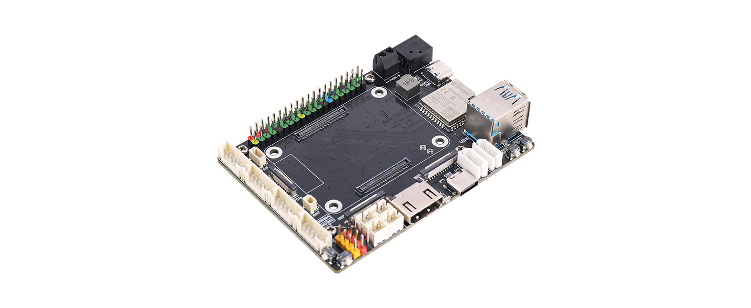
This product adopts a design combining the CM5 core board and ESP32 module, integrating a wealth of peripheral interfaces and functional modules. For video output, it supports 4K high-definition HDMI. For data transmission, it is equipped with dual USB 3.2 and PCIe interfaces, as well as dual MIPI camera and display interfaces. In terms of expandability, it provides the Raspberry Pi standard 40P GPIO and a complete motor drive ecosystem, including interfaces for motors with encoders, DC motors, digital servos and serial bus servos. The onboard QMI8658 IMU delivers high-precision attitude sensing, while the onboard ESP32 module enables wireless communication and drives various types of motors. Power supply supports direct input from a 12V battery or a 5V/5A Raspberry Pi adapter. It also comes with a fan connector, RTC battery connector and dual-function buttons, making it suitable for high-performance mobile computing scenarios such as robotics and embedded vision.
Ⅱ Product Features
- Onboard interfaces include a standard CM5 HDMI connector, dual MIPI connectors, dual USB-A connectors, a PCIe connector, a fan connector, a Micro SD card slot, and an RTC battery connector.
- The board features a Raspberry Pi 40-pin GPIO interface and a standard CM5 connector, supporting integration with Compute Module 5 Lite/eMMC series core boards.
- Equipped with an ESP32-WROOM-32 module, it supports wireless communication via Wi-Fi, Bluetooth, and ESP-NOW.
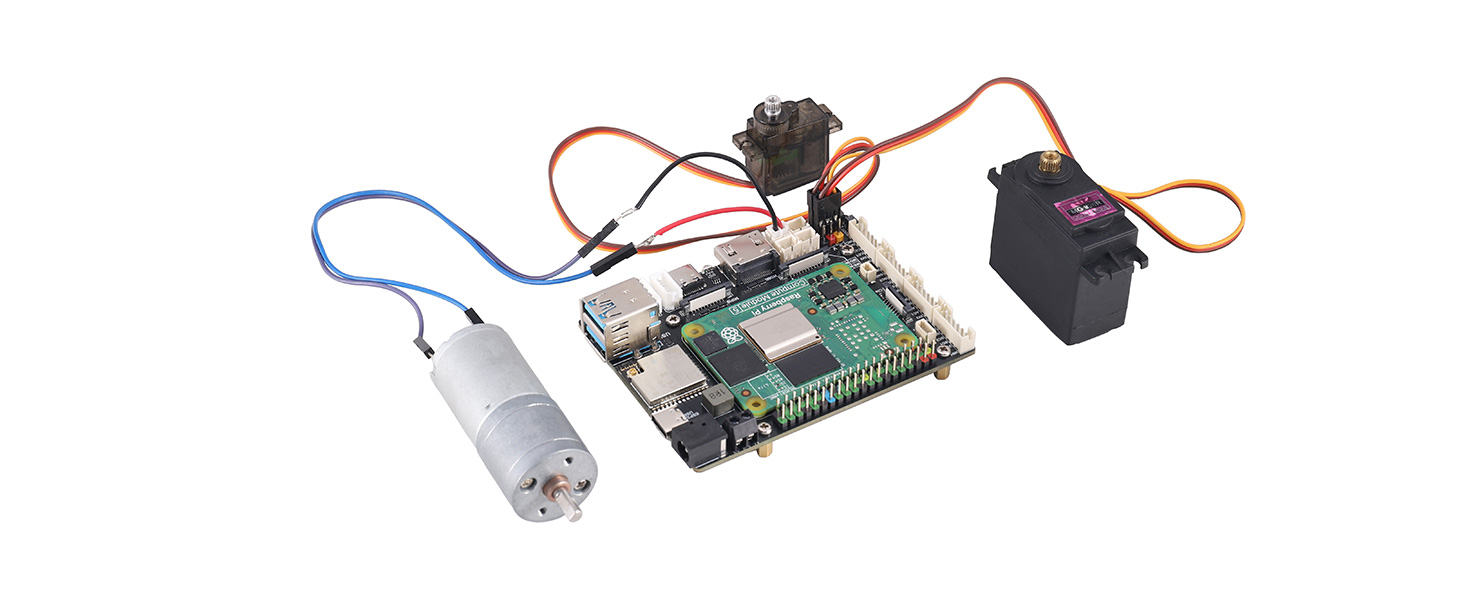
- Onboard one set of digital servo control interfaces, capable of simultaneously controlling up to 4 PWM servos, such as models 996R, 92R, 90S, etc.
- The board also provides motor control interfaces, enabling control of up to four DC motors with encoders or four DC motors without encoders.
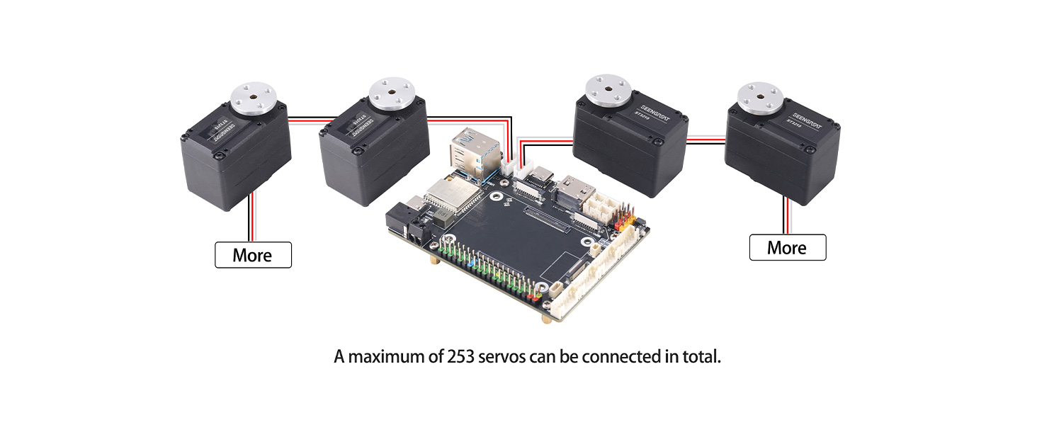
- Onboard two Serial bus servo control connectors, capable of controlling up to 253 bus servos and obtaining servo feedback.
- Features a six-axis IMU, the QMI8658, for real-time acquisition of attitude and heading information.
- Supports power input from a 9–13V DC power source or a 5V/5A Raspberry Pi adapter.
Ⅲ Product Parameters
Main Controller | CM5、ESP32(ESP32-WROOM-32UE) |
Power Supply Voltage | 5V/5A adapter or 9~13V DC power supply |
Connectors | Raspberry Pi 40PIN GPIO Interface |
16PIN PCIe (PCIe Gen2/3 x1) | |
Wireless Communication | WIFI,BLE,ESP-NOW |
USB | USB 3.2 Gen1 × 2(Type A) |
Storage | On-board Micro SD card slot (for versions without eMMC) |
MIPI | 2 × 4-lane MIPI Interfaces (22PIN 0.5mm FFC connector) |
Video | HDMI0 Interface, supports 4K output |
Motion Sensor | 6-axis IMU QMI8658A |
Fan | 5V,4P JST-SH PWM fan connector |
DC Motor with Encoder | PH2.0 6P (supports 12V motors, motor voltage matches DC power input voltage) |
Bus Servo | P=2.5mm 1x3P (supports 12V serial bus servos, e.g., STxxxx series) |
Digital Servo | 4 groups of 2.54mm 1x3P (servo supply voltage: 5V) |
RTC BAT | JST 2P connector |
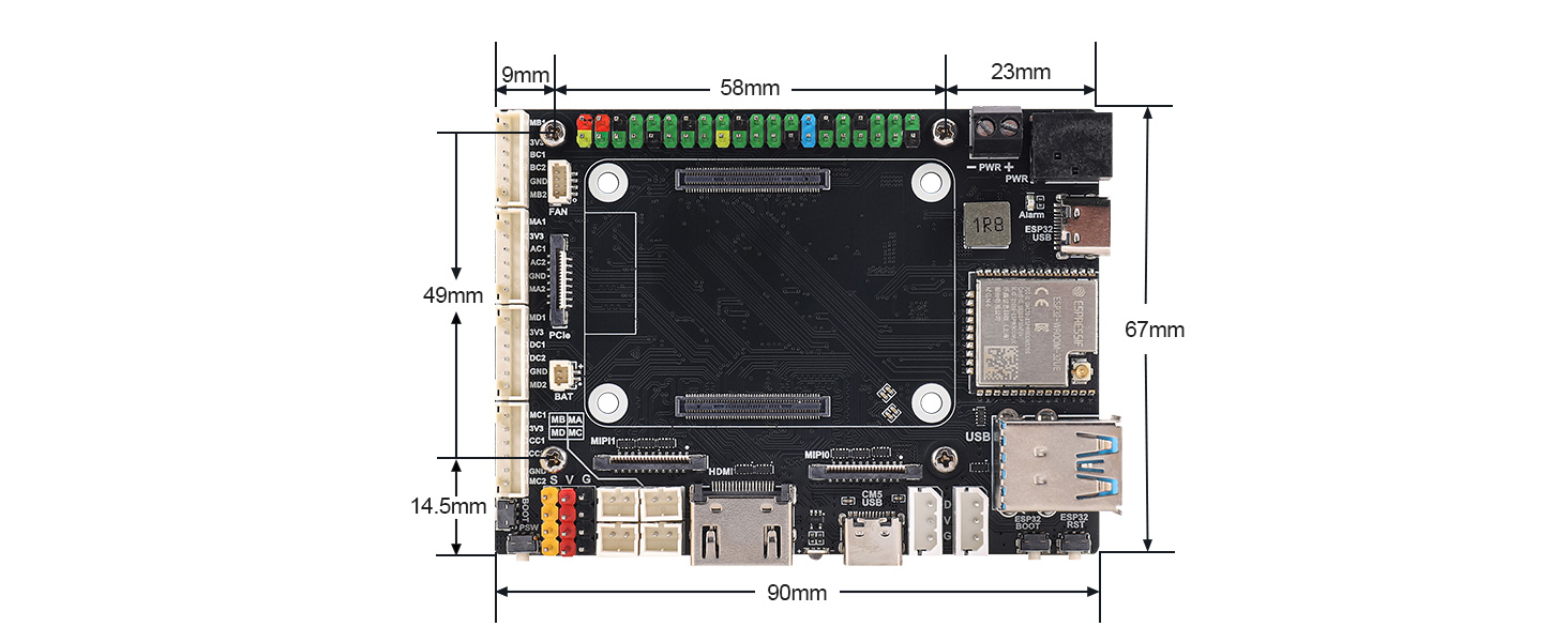
Dimensions | 90mm x 67mm |
Ⅳ Usage
4.1 Resource Introduction
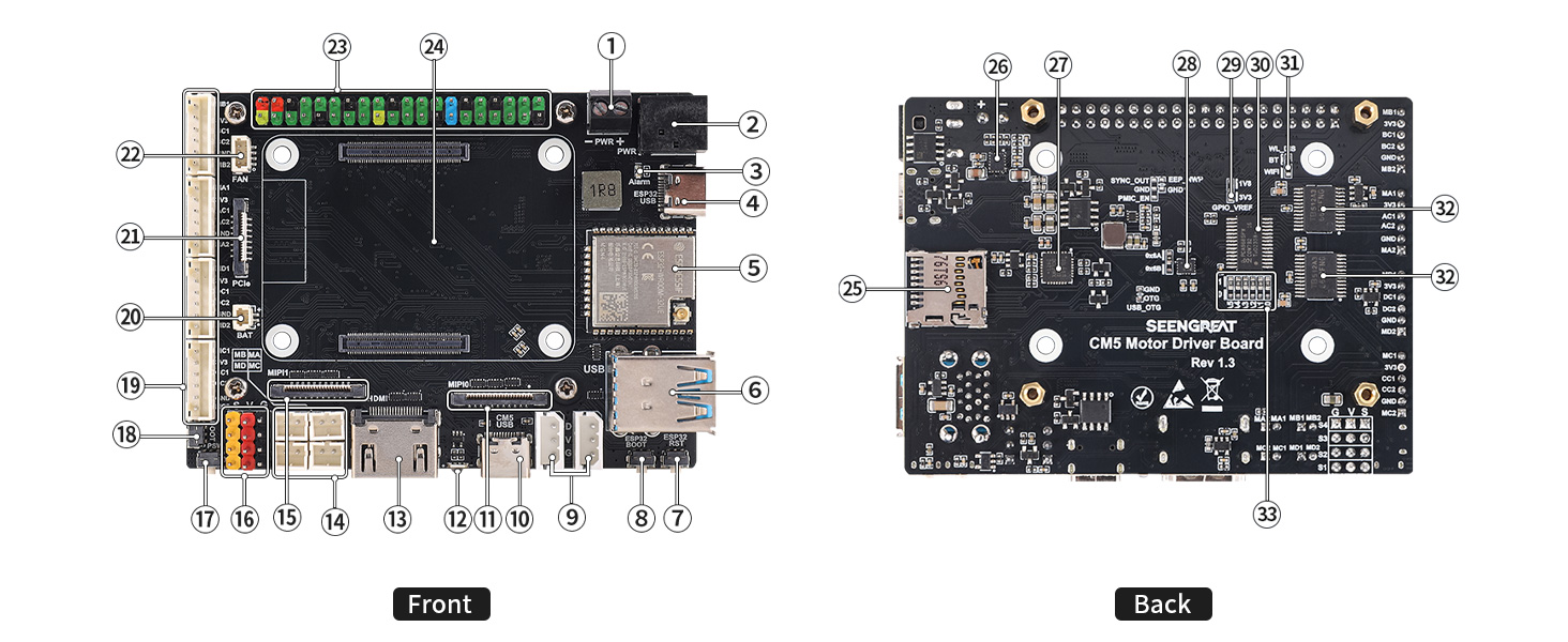
Figure 4-1 Introduction to RPi Connector Adapter Resources
① DC Power Input 3.5mm Terminal Block: Input voltage range is 9~13V, compatible with 12V lithium battery packs or DC power;
② DC Power Input DC-044 Jack: Input voltage range is 9~13V, compatible with 12V lithium battery packs or DC power;
③ DC Power Reverse Polarity Indicator: Illuminates when the DC power input polarity is reversed;
④ ESP32 USB Connector: Used for powering the ESP32, uploading programs, and outputting debugging information;
⑤ ESP32 Module: Model is ESP32-WROOM-32UE;
⑥ USB3.2 Dual-Layer Type-A Female Connector: Supports connection of devices such as mice, keyboards, and USB flash drives;
⑦ ESP32 Reset Button: Resets the ESP32;
⑧ ESP32 BOOT Button;
⑨ Serial Bus Servo Interface: Pin pitch is 2.5mm. The power supply Pin "V" adopts the voltage from the DC power input (see ① and ② in Figure 4-1). It is recommended to use 12V serial bus servos, such as the ST3xx series;
⑩ CM5 USB-C Connector: Provides power for the CM5 and some circuits, and supports system image flashing;
⑪ CM5 4-lane MIPI0 (DSI/CSI) Connector: Compatible with DSI displays or CSI cameras;
⑫ CM5 Power Status Indicator: A dual-color (red and green) indicator with the same function as the red and green LEDs on Raspberry Pi 5;
⑬ Full-size HDMI 2.0 Connector: Connects to HDMI displays and supports 4K output;
⑭ 4-Channel DC Motor Connector: Pin pitch is 2.0mm. The motor voltage is supplied by the DC power input (see ① and ② in Figure 4-1). Users should ensure the motor voltage matches the input power voltage when using DC motors;
⑮ CM5 4-lane MIPI1 (DSI/CSI) Connector: Compatible with DSI displays or CSI cameras;
⑯ 4-Channel Digital Servo Interface: Supports up to 4 units of 5V digital servos, such as MG90S and MG996R;
⑰ CM5 Power Button: Functions the same as the button on Raspberry Pi 5. A short press brings up the shutdown menu, and a long press again turns off the system. A long press forces shutdown, while a short press restarts a powered-off device;
⑱ CM5 BOOT Button: Press before power-on to force boot via USB for system image flashing (useful if the eMMC is damaged);
⑲ 4-Channel DC Motor Connector with Encoder: PH2.0 1x6P, compatible with DC motors equipped with Hall encoders or GMR encoders. The motor drive signals are shared, and the motor voltage is supplied by the DC power input (see ① and ② in Figure 4-1). Users should pay attention to the power voltage when using DC motors;
⑳ RTC Battery Connector: Functions the same as the RTC battery connector on Raspberry Pi 5, allowing connection of an RTC battery to the CM5;
㉑ CM5 PCIe Connector: Functions the same as the PCIe connector on Raspberry Pi 5, supporting expansion boards such as SSDs;
㉒ CM5 Fan Connector: Complies with the pin definition of the Raspberry Pi 5 fan connector. Thus, any fan suitable for Raspberry Pi 5 can be used;
㉓ Raspberry Pi 40-Pin HAT Connector: Has the same GPIO pin functions as the 40-pin header on Raspberry Pi 5;
㉔ CM5 Module Connector: Used for installing the CM5 module;
㉕ microSD Card Slot: A push-type slot, only applicable to the CM5 Lite module;
㉖ DC-DC Chip TPS543820: Converts 12V input to 5V output;
㉗ USB-to-TTL (UART) Chip CP2102: Used for ESP32 program uploading and debugging information output;
㉘ QMI8658A: A 6-axis motion sensor that provides 6-axis motion data of the board;
㉙ CM5 GPIO_VREF Voltage Selection Jumper: Supports 3.3V and 1.8V, with 3.3V as the default;
㉚ PCA9685: A 16-channel PWM output chip. The generated PWM signals are used to drive 4 digital servos and 4 DC motors;
㉛ WIFI and BLE Disable Resistor: Soldering a 0Ω resistor disables these functions;
㉜ TB6612: A motor driver chip that drives 4 DC motors in total;
㉝ PCA9685 Chip I2C Address Setting Resistor;
4.2 Usage Instructions
Do not hot-swap any devices other than USB and HDMI when the system is powered on.
1. System Power Supply
The board is equipped with 4 connectors serving as power input interfaces, namely the DC Power Input 3.5mm Terminal Block (see ① in Figure 4-1), DC Power Input DC-044 Jack (see ② in Figure 4-1), CM5 USB-C Connector (see ⑩in Figure 4-1), and ESP32 USB Connector (see ④ in Figure 4-1).
DC power can be input via either the 3.5mm terminal block or the DC-044 jack (only one connector needs to be connected). The voltage range is 9~13V, and this interface can withstand high power. The power supply directly powers serial bus servos and DC motors. It is recommended to select 12V-rated serial bus servos and DC motors to match the power supply specifications.
If serial bus servos and DC motors are not in use, the board can be powered via the CM5 USB-C connector, which also supports system image flashing for the CM5 (please refer to Section 4.2.1).
The ESP32 USB Connector is only suitable for ESP32 program uploading and debugging, and is not recommended as the power input interface for the entire board.
When the board is under heavy load, it is advisable to use a fully charged 12V lithium battery pack for power supply to prevent system shutdown or other issues caused by insufficient power during operation.
2. Interface Description
The UART0 (TXD0, RXD0) of the ESP32 is interconnected with the UART (RXD-GPIO15, TXD-GPIO14) of the CM5, UART communication between ESP32 and CM5 can be achieved.
The I2C buses of the motion sensor QMI8658A and the PWM chip PCA9685 are connected to both the ESP32 and the CM5. Both devices can control these two I2C slaves, but only one can control as the master at a time. For example, if the CM5 serves as the I2C master to control the QMI8658A and PCA9685, the ESP32 should release control of the I2C bus.
The encoder signal feedback pins of DC motors with encoders(See ⑲ in Figure 4-1.) are only connected to the ESP32, so such DC motors can only be controlled by the ESP32.
Serial bus servos are only connected to IO19 (TXD) and IO18 (RXD) of the ESP32, so serial bus servos can only be controlled by the ESP32.
3. I2C Addresses
After powering on the Raspberry Pi CM5 system, enable the I2C bus (via Applications Menu -> Preferences -> Raspberry Pi Configuration -> Interfaces -> I2C -> ON). Detect the addresses in the terminal using the command i2cdetect -y -a 1. The results will show "6a" and "7f", where "6a" is the address of the 6-axis motion sensor QMI8658A, and "7f" is the address of the PCA9685 chip.
4.2.1 Raspberry Pi System Imaging
For the Lite version Compute Module (without eMMC), it is recommended to flash the image using a microSD card reader. After inserting the microSD card into the computer, format it first. The flashing procedure can be performed by referring to the Raspberry Pi Imager image flashing process described in this section.
The following are the image flashing steps for Compute Modules with eMMC:
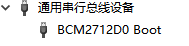
After installing the Compute Module with eMMC, press and hold the BOOT button, then use a Type-C cable to connect the computer (USB 3.0 is recommended) to the onboard CM5 USB-C connector (see ③ in Figure 4-1). At this time, do not connect any other devices to the board, such as HDMI, USB keyboard, or USB mouse. The computer's device manager will then display a device named "BCM2712D0 Boot".
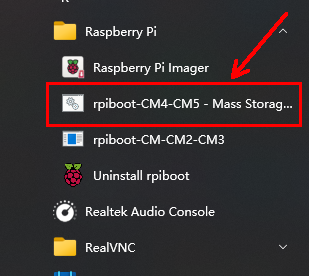
Next, run the rpiboot software (users may install it themselves; download link: https://raw.githubusercontent.com/raspberrypi/usbboot/master/win32/rpiboot_setup.exe), and launch rpiboot-CM4-CM5 – Mass Storage Gadget.
At this point, the following window will pop up:
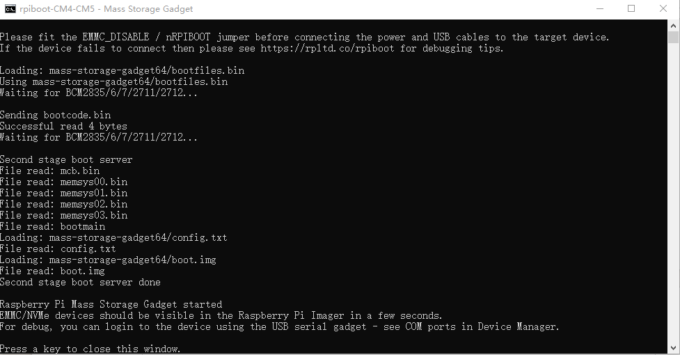
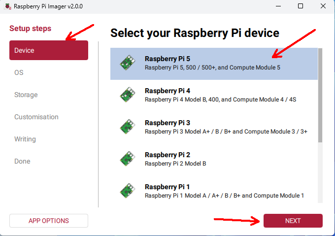
After the above information appears, run the Raspberry Pi Imager software (it is recommended to install a newer version; download link: https://www.raspberrypi.com/software/). In the "Device" field, select "Raspberry Pi 5", then click "Next".
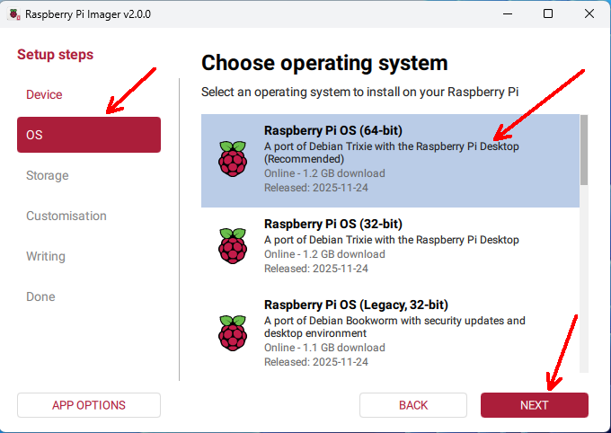
In the "OS" field, select an appropriate operating system, such as "Raspberry Pi OS (64-bit)", then click "Next".
In the "Storage" field, select your image storage device, such as the SD card or the Compute Module eMMC, then click "Next".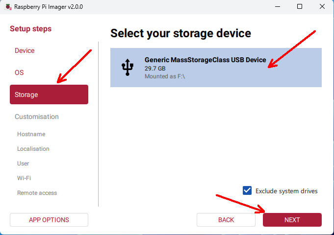
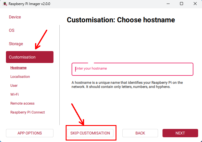
In the "Customization" step, you can select "SKIP CUSTOMIZATION" to proceed without configuring the system, or you may configure the system according to the on-screen prompts.
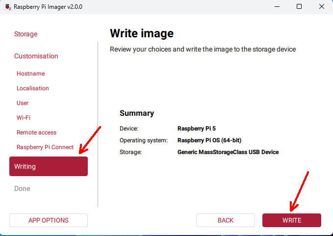
In the "Writing" step, select "WRITE".
Click "I UNDERSTAND, ERASE AND WRITE".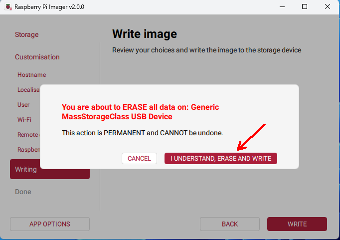
Wait patiently for the writing and verification process to complete, then click "FINISH".
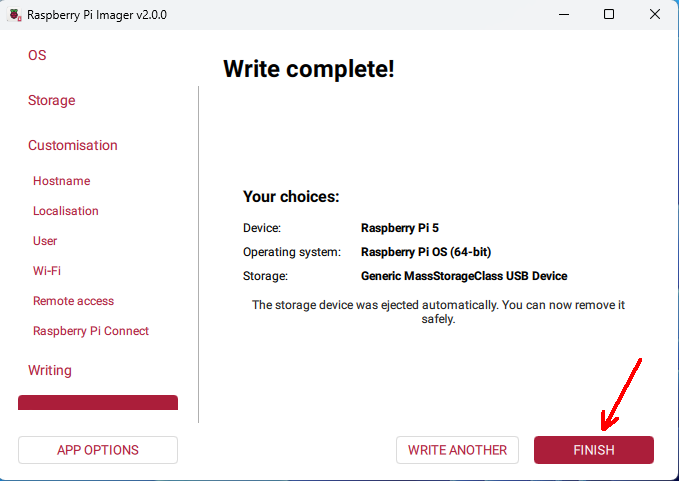
Disconnect the USB cable, connect the mouse, keyboard, and HDMI display, and then power on the board again.
4.2.2 PCIe
When inserting or removing the flexible flat cable (FFC), do not apply excessive force, as this may damage the PCIe connector.
1.PCIe operates in Gen2 mode by default. If PCIe Gen3 needs to be enabled, add the following line to /boot/firmware/config.txt:
dtparam=pciex1_gen=3The configuration will take effect after rebooting.
2. For PCIe module drivers, please refer to the corresponding product Wiki.
4.2.3 MIPI
For the following test procedures, connect the camera or LCD display to the MIPI interface (MIPI0 or MIPI1) while the board is powered off. The camera model used is OV5647, and the LCD display model is Touch Display
When inserting or removing the flexible flat cable, do not apply excessive force to avoid damaging the MIPI connector.
Camera:
Configure /boot/firmware/config.txt as follows:
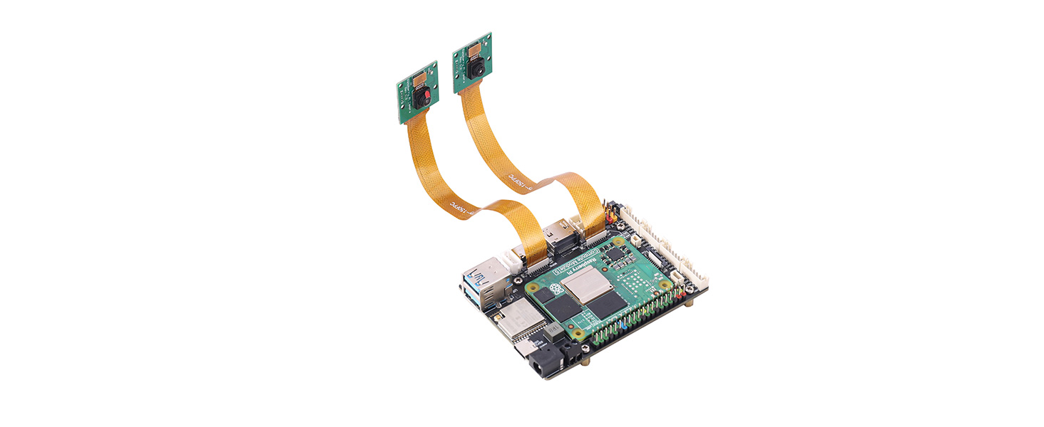
dtoverlay=ov5647,cam0dtoverlay=ov5647,cam1Save the configuration and then power off the board.
Connect two cameras to the board as shown in the figure below
(note the orientation of the ribbon cables):
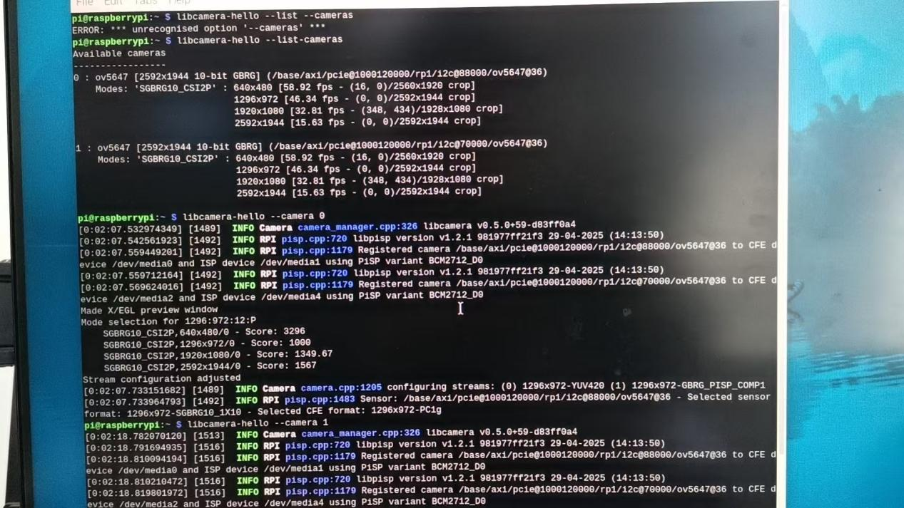
After powering on and booting the system, enter the following commands in the terminal:
libcamera-hello  --list --cameras

libcamera-hello  --camera 1

libcamera-hello  --camera 0
Under normal conditions, both cameras will be detected and can be previewed correctly.
Display and Camera:
Configure /boot/firmware/config.txt as follows:
dtoverlay=ov5647,cam1

dtoverlay=vc4-kms-dsi-ili9881-7inch,dsi0
Shut down the system, then connect the camera to MIPI1 and the display to MIPI0 (the display also requires a 5 V power supply), as shown in the figure: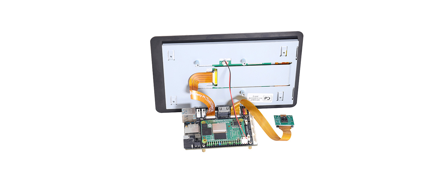
After completing the connections, power on the board. After booting, both the Touch Display 2 and the HDMI display will show output. Use the commands
libcamera-hello --list-camerasAnd
libcamera-helloin the terminal to detect and preview the camera "0: ov5647...".
4.2.4 Fan
Connect the fan to the fan connector (insert it into ㉒ in Figure 4-1).
By default, the Raspberry Pi 5 fan starts rotating only when the temperature reaches 50 °C. If you want the fan to start at other temperatures, add the following entries to /boot/firmware/config.txt and then reboot the system, for example:
dtparam=fan_temp0=36000,fan_temp0_hyst=2000,fan_temp0_speed=90

dtparam=fan_temp1=40000,fan_temp1_hyst=3000,fan_temp1_speed=150

dtparam=fan_temp2=52000,fan_temp2_hyst=4000,fan_temp2_speed=200

dtparam=fan_temp3=58000,fan_temp3_hyst=5000,fan_temp3_speed=255
With this configuration, in principle, the higher the CPU temperature, the higher the fan speed. You can use the command vcgencmd measure_temp in one terminal to check the CPU temperature, and use the command stress -c 4 in another terminal to increase the CPU load. As the load increases, the CPU temperature rises, and the fan speed increases accordingly.
Press Ctrl + C in the terminal running the stress -c 4 command to stop it. After that, you will observe that the CPU temperature decreases and the fan speed gradually slows down.
4.2.5 RTC
Insert the RTC coin cell battery into the battery connector (see ⑳ in Figure 4-1). After powering on the system, set the RTC time in the terminal:
sudo hwclock --set --date="2026-1-1 12:12:00"Synchronize the hardware clock (RTC) to the system clock:
sudo hwclock -s # At this time, the network must be disabled, or network time synchronization must be turned off; otherwise, the time will be reset.
At this point, the output of the date command and the time displayed in the upper-right corner of the screen are synchronized with the time set above. Then disconnect the Raspberry Pi power, wait for a while, and power it on again. You will find that the system clock shown in the upper-right corner is not the previously set time, while the RTC time remains the value that was set above (which can be checked using the sudo hwclock -r command).
The reason for the above time mismatch is that the system does not automatically synchronize the hardware clock time to the system time. A service can be created manually to achieve this:
sudo nano /etc/systemd/system/rtc-sync.serviceAdd the following content:
[Unit]
Description=Sync hardware clock to system time
After=sysinit.target
Before=network.target
[Service]
Type=oneshot
ExecStart=/sbin/hwclock --hctosys --utc[Install]
WantedBy=multi-user.targetThen enable and start the service:
sudo systemctl enable --now rtc-sync.servicePower off the board and power it on again. Run the command sudo hwclock -r, and you will see that the displayed time is consistent with the time shown in the upper-right corner of the screen or the output of the date command.
4.2.6 Arduino IDE Configuration
Open the Arduino official website and download the latest version of the Arduino IDE installation package.
You can select the appropriate installation package according to your operating system. The following steps take Windows as an example for configuration.
After launching the software, add the following URL in "File → Preferences → Additional Boards Manager URLs":https://dl.espressif.com/dl/package_esp32_index.jsonThen click the "OK" button.
4.2.7 IMU
Open /demo-codes/sg/qmi8658_imu/qmi8658_imu.ino using Arduino IDE. Use a USB-C cable to connect the computer to the ESP32 USB connector (see ④ in Figure 4-1). Then select ESP32 Dev Module under Tools → Board → esp32, and select the detected ESP32 port under Tools → Port, as shown in the figure below:
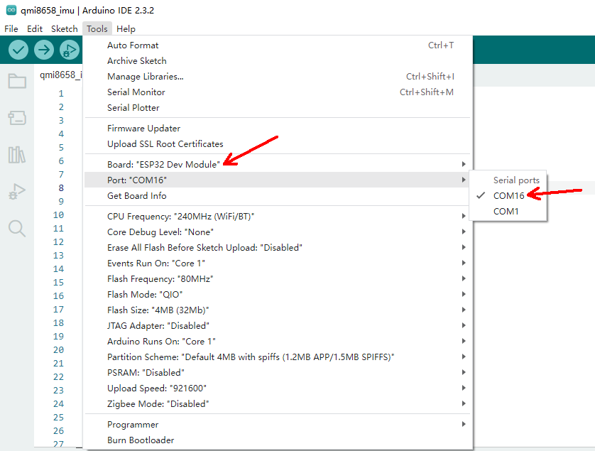
Click the "Upload" button in the upper-left corner to upload the code to the ESP32. Then click Tools → Serial Monitor to open the window and view the sensor data output, as shown in Figure 4-15.
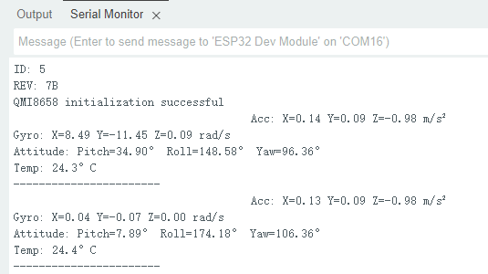
Figure 4-15
4.2.8 Serial Bus Servo
It is recommended to use 12 V serial bus servos for testing. The bus servos must be powered through the DC power input connector (see ① or ② in Figure 4-1).
After downloading the example code at the bottom of this page, open the
/demo-codes/sg/bus-servo/directory and copy the SCServo folder into the libraries directory under the Arduino IDE installation path, for example:
C:\Users\username\AppData\Local\Arduino15\libraries or

C:\Users\username\AppData\Local\Arduino15\packages\esp32\hardware\esp32\3.2.1\libraries.
Different software versions or installation configurations may result in different paths. Users should operate according to their actual system environment. The "username" refers to the computer's user name.
Double-click to open the project file
/demo-codes/sg/bus-servo/Bus-Servo/Bus-Servo.ino.Select ESP32 Dev Module under Tools → Board → esp32, then select the detected ESP32 port under Tools → Port. Click the "Upload" button in the upper-left corner to upload the code to the ESP32. After the upload is complete, the serial bus servo will rotate back and forth.
4.2.9 Digital Servos and DC Motors
The test file for these two types of motors is cm5-pca9685.py, which can be tested under the Raspberry Pi system. The functions of this file include DC motor driving (see ⑭ in Figure 4-1) and PWM servo driving. After installing the motors and servos to be tested, power the board using a DC power supply. After the system boots, enable the I2C bus, then use i2cdetect -y -a 1 to detect the PCA9685 address. If "7f" appears in the results, it indicates that the address has been detected successfully. Then enter the command sudo python3 cm5-pca9685.py to observe the rotation of the servos and motors.
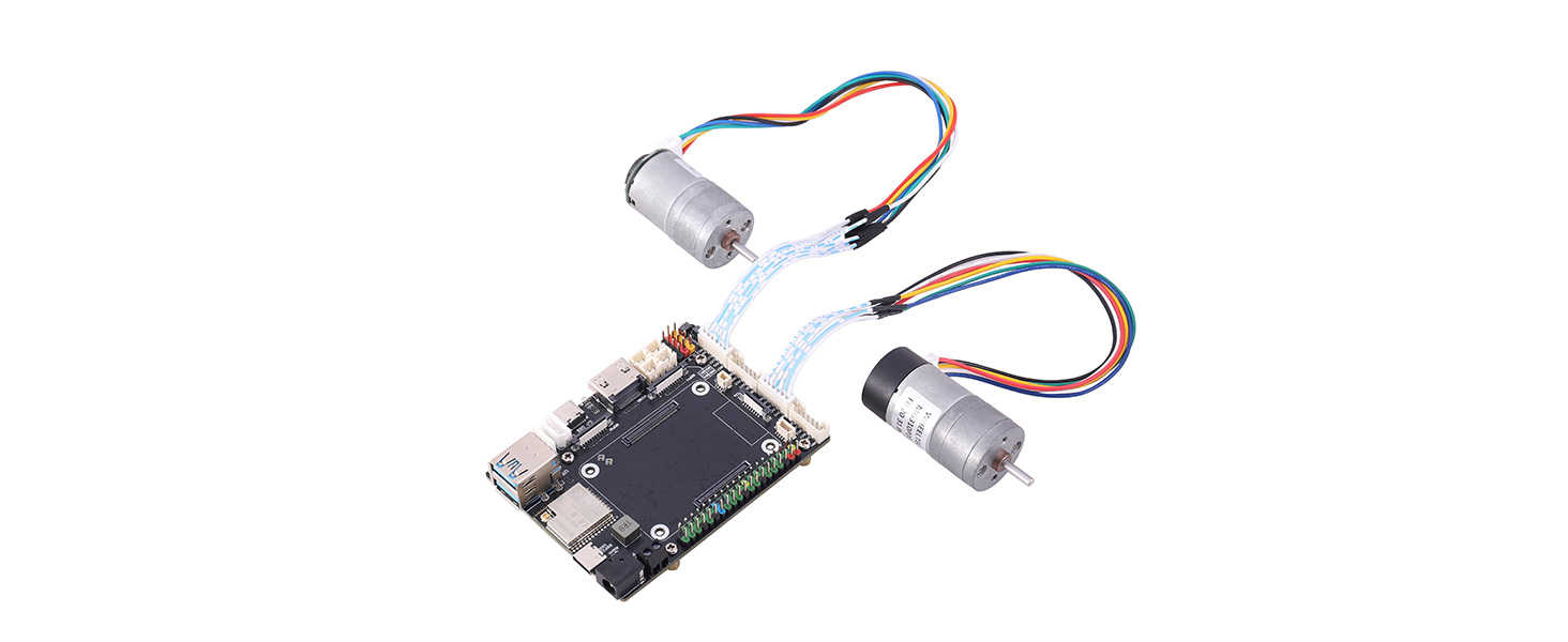
4.2.10 Encoder DC Motor
Before connecting the motor to the board, please carefully verify the pin definitions between the motor leads and the connector to avoid damage to the circuit board and the motor.
The pin definitions of the encoder DC motor interface are shown in Table 2-1:
Pin | Description |
MX1 | Motor output + |
3V3 | Encoder power supply (3.3 V) |
XC1 | Encoder output channel A |
XC2 | Encoder output channel B |
GND | Encoder ground |
MX2 | Motor output − |
In the table, "X" represents "A", "B", "C", or "D". For example, the pin definitions of group A are MA1, 3V3, AC1, AC2, GND, and MA2 in sequence; the pin definitions of group B are MB1, 3V3, BC1, BC2, GND, and MB2 in sequence. The pin definitions of the other two connectors follow the same rule.
Open the project file /demo-codes/sg/enc_4motor/enc_4motor.ino. Then go to Tools → Manage Libraries..., enter Adafruit PWM Servo Driver in the search box, and click "INSTALL" to install it, as shown in Figure 4-18.
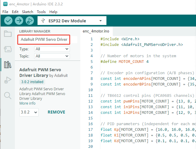 Figure 4-18
By default, this code connects motors with GMR encoders to the MAx (2.0 mm 1×6P) and MBx (2.0 mm 1×6P) connectors, but only MAx is actually enabled. Motors with Hall encoders are connected to the MCx (2.0 mm 1×6P) and MDx (2.0 mm 1×6P) connectors, but only MCx is actually enabled. As shown in the code in Figure 4-19, users can modify the code according to their actual requirements.
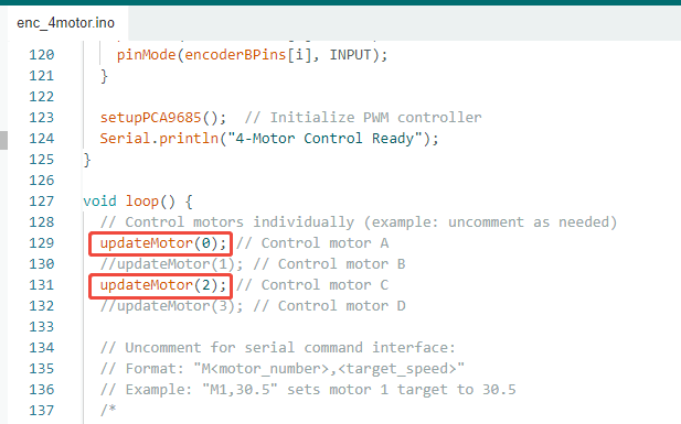 Figure 4-19
The example code implements closed-loop speed control of the motors. The array float enc_ppr[MOTOR_COUNT] represents the number of encoder pulses per revolution for the motors connected to the four connectors. The array float targetSpeeds[MOTOR_COUNT] defines the target speeds. The arrays float Kp[MOTOR_COUNT], float Ki[MOTOR_COUNT], and float Kd[MOTOR_COUNT] are the PID parameters for the speed control loop. Users can modify these parameters according to their actual application requirements.
5. Resources
SERVO_DRIVER_WITH_ESP32_ST_FACTORY
Compute Module 5 Documentation