Image Digitization
Ⅰ Image Creation
The screen supports 4 kinds of color display.They are black,white,red and yellow.The above 4 colors are standard colors.You can actually refer to the color table of the drawing software.When making pictures,you need to make a picture with 384x168 resolution into a bitmap that only contains black,white,red and yellow 4 colors.And save the picture in BMP or JPG format.
Ⅱ Mode Extraction
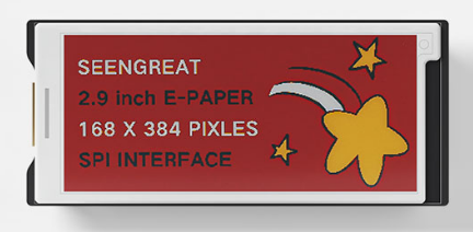
Figure 6-2
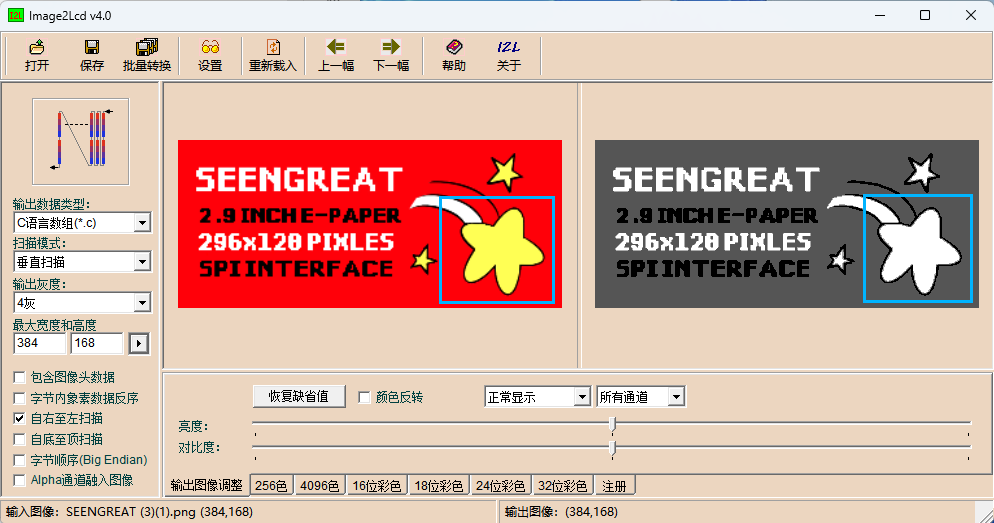
You can use the Image2Lcd software for mode extraction. This software is provided in the compressed package. To achieve the effect shown in Figure 6-2, follow the mode extraction parameter settings as shown in Figure 6-3:
1. Open the image that needs to be extracted;
2. Output data type: Select "C language array (*.c)".
3. Scanning method: Select "Vertical Scanning";
4. Output grayscale: select "4 gray";
5. Maximum width and height: Select "384" and "168", and click the arrow behind to confirm;
6. As shown in the figure below, only the third item is checked;
 7. "Color Inversion" does not need to be checked;
8. Click "Save" to save the converted array to a file with the extension ".c", and the 384x168 resolution image will generate a 16128 byte image array;
9. Finally, replace the corresponding array in the example program code with the array from the ".c" file.
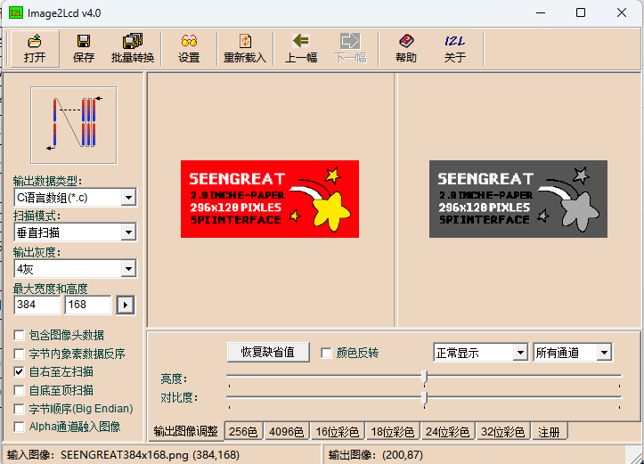
Figure 6-3
Picture Impression Explanation:
In the Image2Lcd software, when the grayscale output is set to "4 Grayscale", the corresponding relationship is as follows:
The original color of the picture | Converted color |
Red | Dark gray |
Yellow | Light gray |
Black | Black |
White | White |
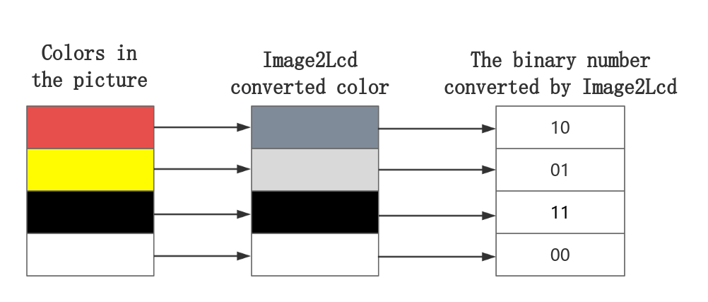
As mentioned in point 8 above, a picture with a resolution of 384x168 will generate an image array with a size of 16128 bytes, that is, 16128x8=129024 bit, and the actual ink screen has 384x168=64512 pixels.It can be known that one pixel is represented by 2 bits (129024/64512=2).In the Image2Lcd software, the corresponding relationship between the converted colors and the 2-bit binary code is as shown in the following table:
The original color of the picture | Converted color | Binary representation of the converted color in the Image2Lcd software |
Red | Dark gray | 10 |
Yellow | Light gray | 01 |
Black | Black | 11 |
White | White | 00 |
In the ink screen, the representation of the four colors of black, white, red and yellow is different from the representation in the Image2Lcd software.The color representation in the ink screen and its corresponding relationship with 2-bit binary is as shown in the following table:
The colors displayed on the ink screen | 2 binary numbers that should be written to the ink screen |
White | 01 |
Yellow | 10 |
Red | 11 |
Black | 00 |
From the above table, it can be seen that the 16128-byte array obtained from the converted image in the Image2Lcd software cannot be directly written to the ink screen.It needs to be converted. The following figure is the conversion relationship between the array generated by Image2Lcd and the data written to the ink screen:
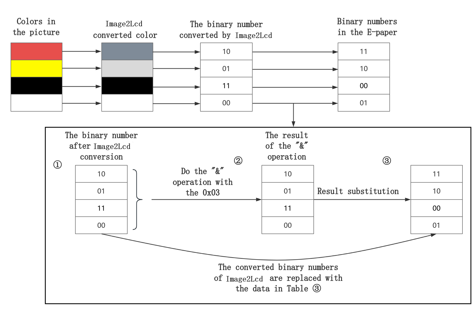
After the above conversion, the binary number of the original image converted in the Image2Lcd software is replaced by the binary number corresponding to the color of the original image in the ink screen.
When a byte is passed in, take 0xF5 as an example:
0xF5 -> 11 11 01 01
Every two digits of it do the "&" operation with 0x03 (0000 0011). According to the operation result to determine the color, the following table is the corresponding relationship between the operation result and the color:
The original color of the picture | Converted binary numbers in Image2Lcd software | "&" operation result | Result substitution | The color of the result of the substitution is the corresponding in the ink screen |
Black | 11 | 11 | 00 | Black |
Black | 11 | 11 | 00 | Black |
Yellow | 01 | 01 | 10 | Yellow |
Yellow | 01 | 01 | 10 | Yellow |
11 & 11 -> 11, i.e. hexadecimal 0x3, at this time 11 is replaced with 00, and 00 is represented as black in the ink screen;
11 & 11 -> 11, i.e. hexadecimal 0x3, at this time 11 is replaced with 00, and 00 is represented as black in the ink screen;
01 & 11 -> 01, i.e. hexadecimal 0x1, at this time 01 is replaced by 10, and 10 is represented as yellow in the ink screen;
01 & 11 -> 01, i.e. hexadecimal 0x1, at this time 01 is replaced by 10, and 10 is represented as yellow in the ink screen;
It can be seen that 0xF5 is in the area where black and yellow meet.0xF5 was replaced with 0x0A and written to the e-ink screen.
Note that the colors in the picture must be the standard 4 colors of black, white, red and yellow. If the color has color difference, it may be recognized as different colors.As follows, the light yellow in the picture is recognized as white:
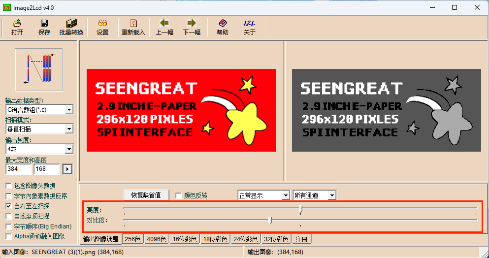
Or you can achieve the desired effect by adjusting the "brightness" and "contrast".
Ⅲ Usage of the Digitized Data
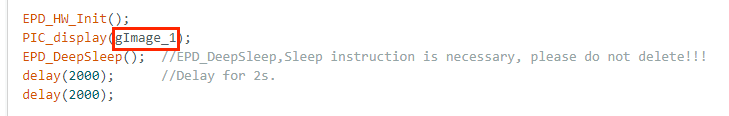
Take the Arduino sample code as an example: The Ap_29demo.h file stores the image digitized data (hex array). You can add the converted data to the Ap_29demo.h file following the specified format.
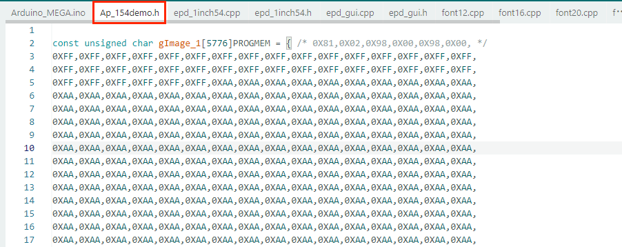
Replace the variable 'gImage_1' in the code below with your own data.