IV Usage
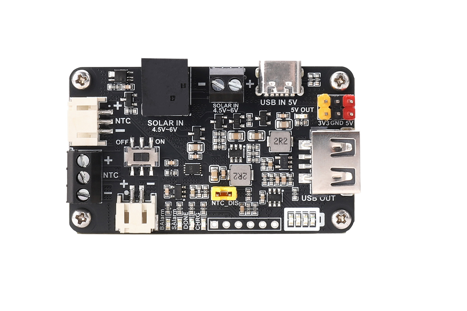
4.1、Resource Overview
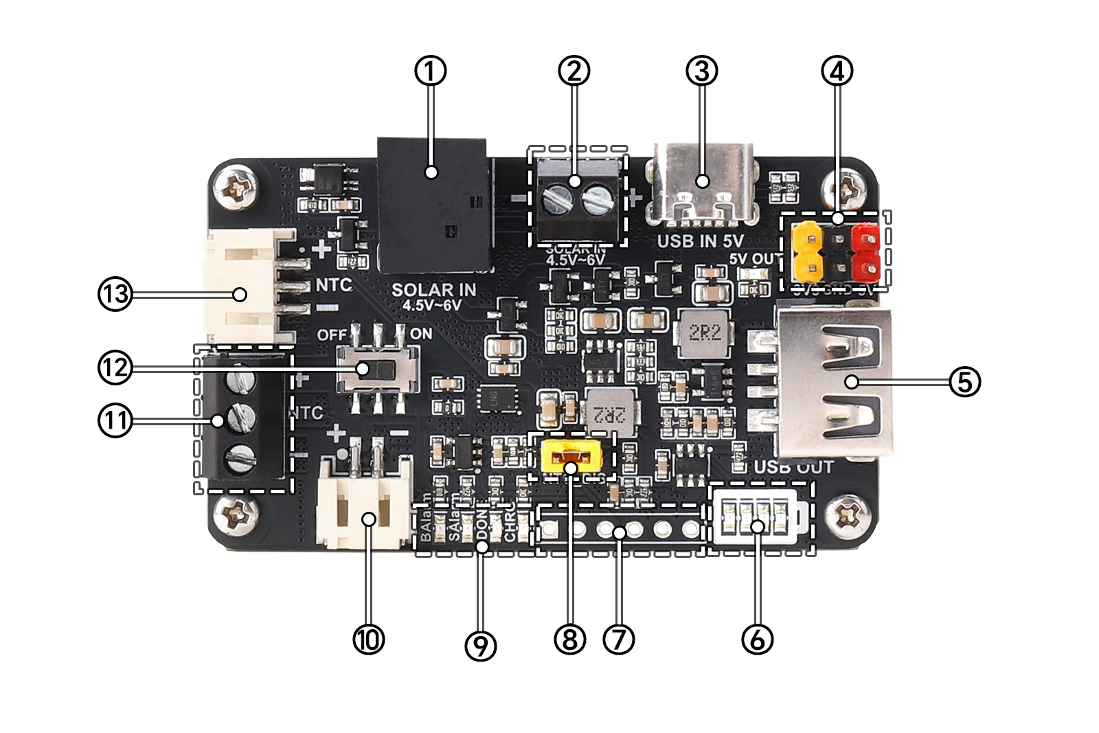
① DC-044 solar charging jack: A 5V solar panel or adapter can be connected through this power jack;
② 3.5mm solar charging terminal: A 5V solar panel or adapter can be connected through this terminal;
③ USB C charging port: The battery is charged through this USB connector (if a solar panel is connected at the same time, the charging from the solar panel will be disconnected);
④ Power output pin header (2.54mm pitch): It can provide 5V and 3.3V outputs externally, and together with the USB A connector, they can provide a maximum power of 5W externally.
⑤ USB A output port: It can output a maximum power of 5V/1A through this port (together with the power output pin header);
⑥ Battery voltage indicator;
⑦ Pins for battery charge-discharge status, battery level, and power output control are led out (pin headers are un-soldered), including GND, charging status pins CHRG and DONE, battery voltage (already through resistor voltage division), 5V output enable, 3.3V output enable;
⑧ NTC function setting jumper cap: Short circuit indicates disabling the NTC detection function, and open circuit indicates enabling the NTC detection function, in which case the connected battery is required to have an NTC resistor.Battery Charge/Discharge Status and Voltage Pins (header not soldered).
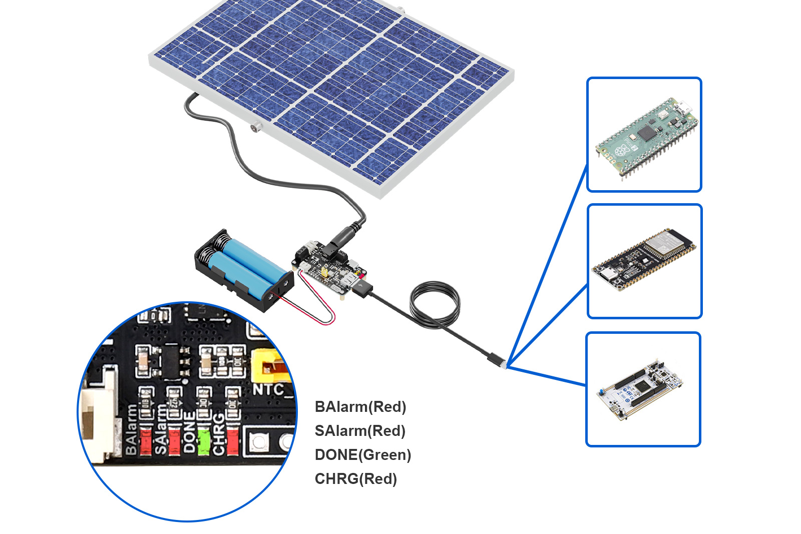
⑨ Status indicators: CHRG->Battery is charging, DONE->Battery is fully charged, SAlarm->Solar panel input reversed, BAlarm->Battery connection polarity reversed;
⑩ PH2.0 battery connector without NTC: When connecting the battery here, please short-circuit NTC_DIS (⑧ in Figure 4-1);
⑪ 3.5mm battery terminal: When it is necessary to connect a battery with an NTC resistor, please connect the NTC pin to the middle NTC pin and open the NTC_DIS pin header. If the battery does not have the NTC function, just connect the battery with correct polarity and short-circuit NTC_DIS;
⑫ Power switch;
⑬ PH2.0 battery input connector with NTC;
4.2、Interface Description
1. Two solar panel input interfaces (see ① and ② in Figure 4-1): one DC-044 power jack and one KF128L-3.5-2P terminal. Users can select one of them to connect to the Solar Energy Manager C module according to the output interface of the 5V solar panel, with an input voltage of 4.5-6V.
2. One USB Type-C input port (see ③ in Figure 4-1): When USB Type-C is selected to charge the battery, the board will actively disconnect the solar panel charging.
3. Three 18650 battery connectors (see10、11、13 in Figure 4-1): Users can select any one of them to connect a 3.7V lithium battery according to the battery type. Please pay attention to the positive and negative poles of the battery when connecting, and do not reverse the positive and negative poles of the battery. The module is equipped with battery reverse connection protection and reverse connection alarm. If the BAlarm indicator is always on after installing the battery, it means that the positive and negative poles of the battery are reversed, and the battery should be reinstalled correctly immediately.
4. Battery Charge/Discharge Status and Battery Level Pins:(2.54mm pitch header pads, silkscreen shown on the back of the board)The pin definitions are listed in the table below (Table 4-1):
Pin Name | Direction | Description |
GND | Power ground | |
DONE | Output | Full charge indication for solar charging mode, connected to the cathode of the DONE indicator, with a 10K resistor pulled up to 3.3V. Low level indicates that the battery is fully charged in Solar charging mode, and high level indicates that it is not fully charged. |
CHRG | Output | Charging indication for solar charging mode, connected to the cathode of the CHRG indicator, with a 10K resistor pulled up to 3.3V. Low level indicates that the battery is being charged in Solar charging mode, and high level indicates that it is not being charged. |
V_BAT | Output | The battery voltage has been divided by two resistors (the upper resistor is 4.7KΩ and the lower resistor is 10KΩ). The voltage at this pin is calculated by the formula: V_BAT = VBAT × (10/(10+4.7)) V, where VBAT represents the actual voltage of the battery. |
5V_EN | Input | This pin is default high level to enable 5V output. When the user connects this pin to GND low level, the 5V output will be disabled, and the 3.3V output will also be disabled at this time (because the 3.3V power supply is modulated and output by the 5V power supply). |
3V3_EN | Input | On the premise that 5V output is enabled, this pin is default high level to enable 3.3V output. If the user connects it to GND, the 3.3V output will be disabled. |
4.3、Note
- When installing the battery and connecting the solar panel, please ensure the correct polarity and avoid reversing the connections.
- Do not directly touch the core components with your hands during operation; ensure proper static protection.
- When supplying power to the load via the header pins, ensure the correct polarity and avoid reversing the connections.
- When charging with a solar panel, it is recommended to use a solar charging panel of the 5V specification.
4.4、Related Instructions
1. Regarding battery charging power: The lower the battery level, the higher the charging power; the higher the output power of the solar panel, the higher the charging power. When the solar panel has sufficient output power and the battery level is low, the maximum charging current is approximately 950mA.
2. The board supports simultaneous charging and discharging, meaning it can discharge while being charged via solar power or via USB.
3. The board is equipped with 3 battery connectors. If the user connects a lithium battery with NTC (10KΩ recommended) (see (11)or (13) in Figure 4-1), the NTC_DIS 2P pin header should be set to an open circuit. If the user connects a lithium battery without NTC (see (10)or (11)and in Figure 4-1), the NTC_DIS 2P pin header should be set to a short circuit.
4. When the Solar interface and USB interface are used for charging simultaneously, the charging current of the Solar interface will be actively disconnected, meaning the board prioritizes USB charging.
5. Onboard LED Indicators:The definitions of the onboard LED indicators are shown in Table 4-2 below:
BAlarm (Red) | The LED will turn on when the battery polarity is reversed. |
SAlarm (Red) | The LED willturn on when the polarity of the Solar panel's charging power supply is reversed. |
CHRG (Red) | This LED will turn on when the Solar panel is charging. |
DONE (Green) | This LED will turn on when the Solar panel is fully charged. |
Battery Voltage (see ⑥ in Figure 4-1: 4 red LEDs) | Indicates battery voltage; more LEDs lit from left to right mean higher battery voltage, and fewer mean lower voltage |
V Resources
datasheet:
VI Appendixes
5.1 Precautions
- Please do not remove or insert the modules while it is running!
- Please follow all warnings and guidance information marked on the product.
- Please keep this product dry.If it is splashed or soaked by any liquid accidentally, please power off immediately and dry thoroughly.
- Please pay attention to the ventilation and heat dissipation in the environment of running the product to avoid the damage of components by high temperature.
- Please do not use or store the product in dusty or dirty environment.
- Please do not use the product in alternating environment between hot and cold to avoid condensation damage to the components of the product.
- Please do not handle the product roughly. Falling, knocking or violent shaking may damage the circuit and components.
- Please do not clean this product with organic solvents or corrosive liquids.
- Please do not repair or disassemble our products by yourself. If the products break down, please contact us for maintenance in time.Unauthorized repair may damage the product,so the resulting damage will not be covered by warranty.