Ⅵ Usage

All the demo codes provided by this product are based on the 4-wire SPI mode, so the BS selection switch on the back of the board is set to "0" by default.
6.1 Interface Configuration
E-paper Interface | SPI |
VCC | 3.3V/5V |
GND | Power ground |
RST | External reset pin (low level reset) |
BUSY | Busy status output pin |
D/C | Data/Command control pin (high level for data, low level for command) |
MOSI | SPI communication MOSI pin |
CS | SPI chip select pin (active low) |
CLK | SPI communication SCK pin |
Advantages of EINK
E-paper display utilizes microcapsule electrophoretic technology for displaying, the principle is: charged particles suspended in clear fluid will move to sides of microcapsule when electric field is applied, making the microcapsule become visible by reflecting ambient light, just as traditional printed paper.E-paper display will clearly display images/texts under lamplight or natural light, requires no backlight, and features nearly up to 180° viewing angle. It is usually used as e-reader due to its paper-like effect.
Raspberry Pi Platform
In order to be compatible with the bullseye and bookworm systems, this sample code is divided into wiringpi library version and lgpio library version, where the bullseye system uses the wiringpi library version, and the bookworm system uses the lgpio library version.
6.2.1 Interface Configuration
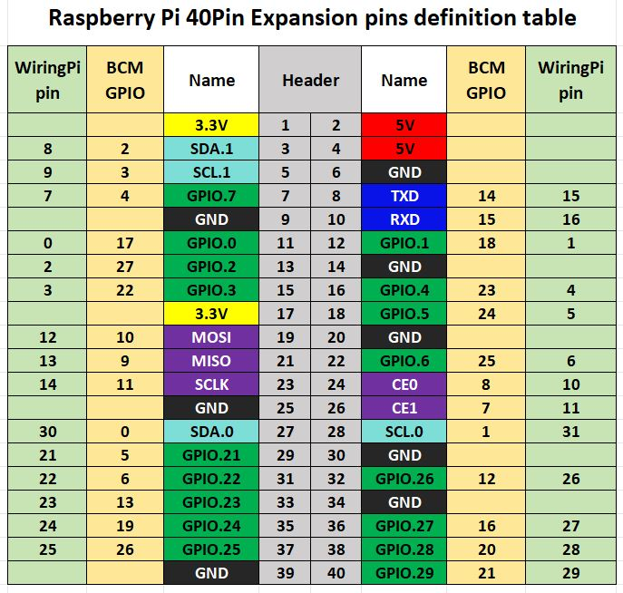
Figure 6-1 Raspberry Pi interface diagram
The following figure shows the wiring diagram between the Raspberry Pi and the ink screen: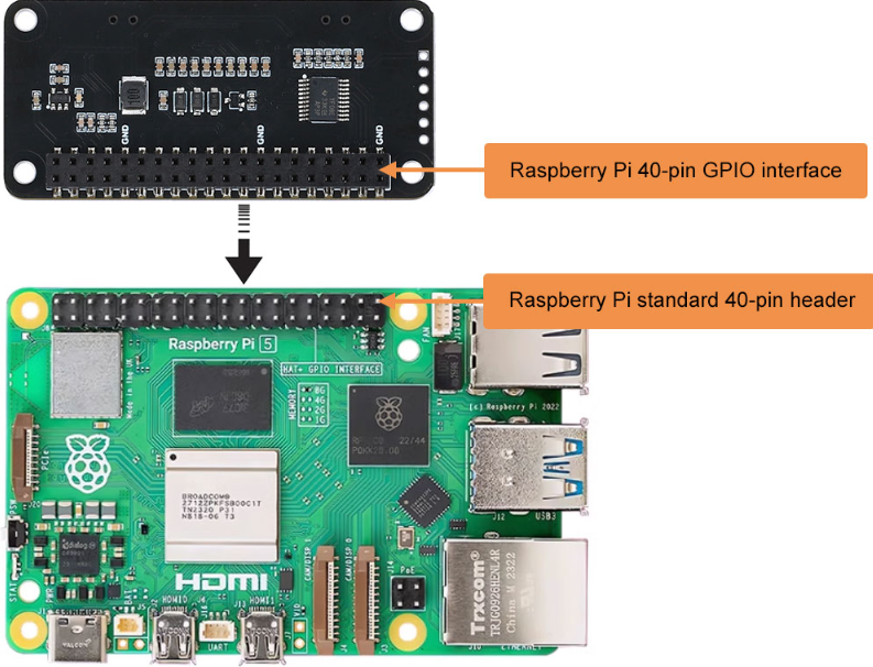
The example programs for the Raspberry Pi board use the BCM numbering for pin definitions with the lgpio library and the wiringpi numbering with the wiringpi library. The pin wiring definitions for the Raspberry Pi board are as shown in the table below:
E-paper Interface (E-paper Connector) | Pin Function | BCM Numbering | Wiringpi Numbering |
VCC | 3.3V | ||
GND | GND | ||
BUSY | Busy Signal Pin | 24 | 5 |
RSTN | Reset | 17 | 0 |
D/C | Command/Data Select | 25 | 6 |
SDA | SPI Data Out/Slave In | 10 | 12 |
SCL | SPI Clock | 11 | 14 |
CSB | SPI Chip Select | 8 | 10 |
LED1 | 4 | 7 | |
LED2 | 18 | 1 | |
K1 | 27 | 2 | |
K2 | 22 | 3 |
6.2.2Library Installation
1. Wiringpi Library Installation
sudo apt-get install wiringpi
wget https://project-downloads.drogon.net/wiringpi-latest.deb
Upgrade Raspberry Pi 4B Version:
sudo dpkg -i wiringpi-latest.deb
gpio -v
If version 2.52 appears, it indicates that the installation has been successful.
- For the Bullseye branch system, use the following command:
git clone https://github.com/WiringPi/WiringPi
cd WiringPi
. /build
gpio -v
Running "gpio -v" will show version 2.70. If it doesn't appear, it means there is an installation error.
If an error message "ImportError: No module named 'wiringpi'" appears when running a sample program in Python version, run the following command:
- For Python 2.x version
pip install wiringpi- For Python 3.x version
pip3 install wiringpiNote: If the installation fails, you can try the following compiled installation.
git clone --recursive
https://github.com/WiringPi/WiringPi-Python.git
Note: The --recursive option can automatically pull submodules. Otherwise, you need to download them manually.
Enter the newly downloaded WiringPi-Python folder and use the following commands to compile and install:
- For Python 2.x version
sudo python setup.py install- For Python 3.x version
sudo python3 setup.py installIf the following error occurs:
In this case, enter the command sudo apt install swig to install SWIG. After completing the installation, run sudo python3 setup.py install to compile and install. If you see similar information, it indicates that the installation was successful.
2. lgpio Library Installation
For the Bookworm system, the example programs use the lgpio library. The installation command for this library is:
wget https://github.com/joan2937/lg/archive/master.zip
unzip master.zip
cd lg-master
Make
sudo make install
3. Python Library Installation
The example program uses the Python3 environment. To run the Python example program, you need to install the PIL, numpy, and spidev libraries.
Enter the following commands to install them:
sudo apt-get install python3-pil
sudo apt-get install python3-numpy
sudo apt-get install python3-pip
sudo pip3 install spidev6.2.3Enable the Communication Interface
sudo raspi-configEnable the SPI Interface:
Interfacing Options->SPI->YesCheck the enabled SPI devices:
ls /dev/spi*This will print: "/dev/spidev0.0" and "/dev/spidev0.1"
6.2.4 ExampleCode
1. Python Version Example
Using the lgpio library as an example, navigate to the /demo codes/raspberry_pi/lgpio/python directory.
sudo python3 gui_demo.pyAfter entering the above commands, you can observe the e-paper display.
2. C Version Example
Using the lgpio library as an example, navigate to the /demo codes/raspberry_pi/lgpio/c directory:
sudo make clean
sudo make
sudo ./main
After entering the above commands, you can observe the e-paper display.
6.3 Arduino Platform
6.3.1 Interface Configuration
Table 6-2 shows the wiring definitions between the Arduino Mega and the e-paper display:
E-paper Interface | Arduino Mega |
VCC | 5V |
GND | GND |
CS | D53 |
CLK | D52 |
MOSI | D51 |
DC | D8 |
RST | D9 |
BUSY | D10 |
Table 6-2 E-paper Display and Arduino Mega Pin Definitions
The following diagram shows the wiring diagram between the Arduino Mega and the ink screen:
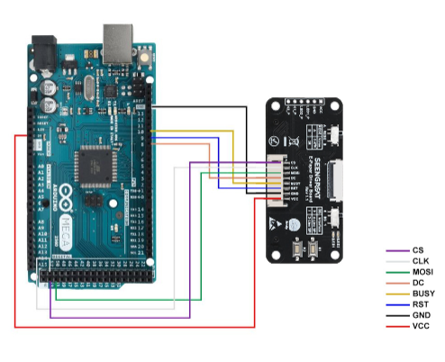
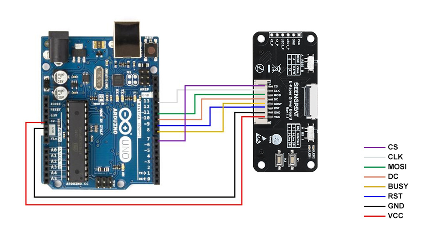
Table 6-3 E-paper Display and Arduino UNO Pin Definitions:
E-paper Interface | Arduino UNO |
VCC | 5V |
GND | GND |
CS | D7 |
CLK | D13 |
MOSI | D11 |
DC | D10 |
RST | D9 |
BUSY | D8 |
Table 6-3 E-paper Display and Arduino UNO Pin Definitions
The following diagram shows the wiring diagram between the Arduino UNO and the ink screen:
6.3.2 Arduino IDE Installation
1. Download the Arduino IDE installation package from the Arduino official website(Software | Arduino).
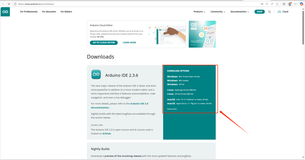
Select "JUST DOWNLOAD".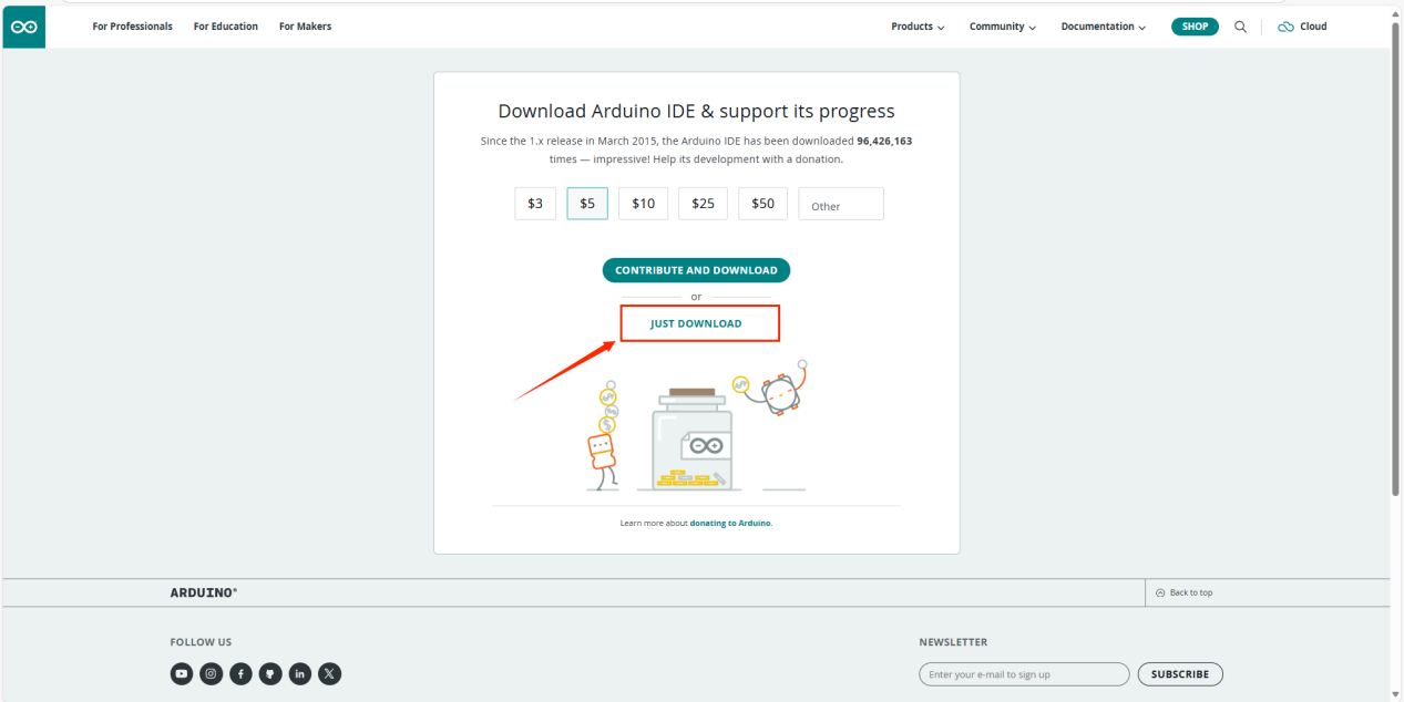
2. After the download is complete, click "Install".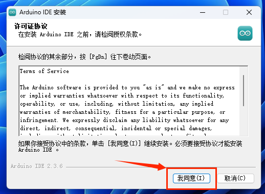
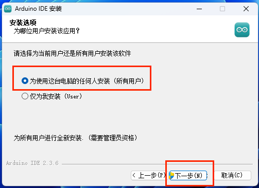
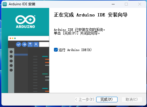
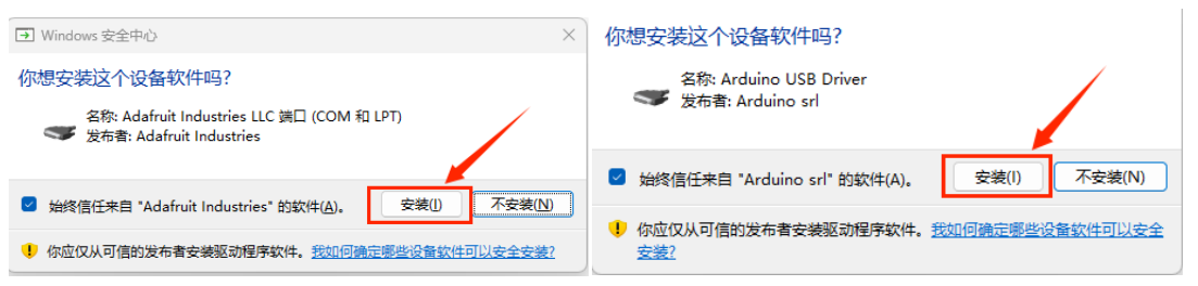
During the installation process, you will be prompted to install the driver. Just click "Install" to proceed.
3. Connect the Arduino development board.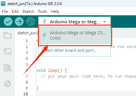
6.3.3Run Program
Open the project file /demo codes/Arduino_MEGA/Arduino_MEGA.ino or /demo codes/Arduino_UNO/Arduino_UNO.ino in the Arduino IDE. Select the correct Board and Port based on your setup. Click Verify, and once the verification is successful, upload it to the module. Observe the e-paper display.
Note: Due to the small memory resources of Arduino, when using Arduino related routines, it is not possible to refresh and display multiple pictures at the same time.Please refresh as few images as possible, otherwise you will get a message that the memory is out.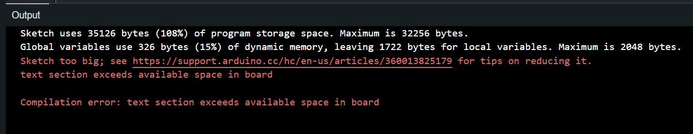
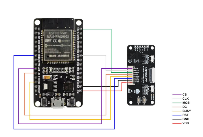
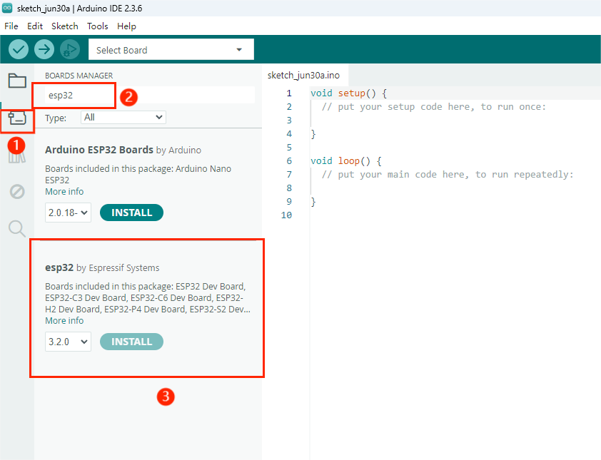
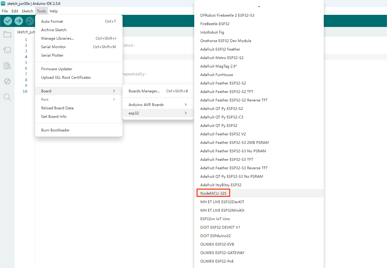
6.4 ESP32 Platform
The example program uses the ESP32 module ESP32-WROOM-32E.(Model of the board in the IDE:NodeMCU-32S)
6.4.1 Interface Configuration
E-paper Interface | ESP32 Interface |
VCC | 3.3V |
GND | GND |
CS | IO27 |
CLK | IO18 |
MOSI | IO23 |
DC | IO14 |
RST | IO33 |
BUSY | IO13 |
Table 6-4 E-paper Display and ESP32 Pin Definitions
The following figure shows the wiring diagram between ESP32 and the ink screen:
6.4.2 Environment Configuration
1. Install the Arduino IDE.
2. Configure the address of the ESP board manager.
Paste the URL below into the "Additional boards manager URLs".
https://dl.espressif.com/dl/package_esp32_index.json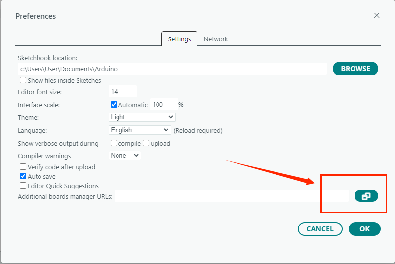
3. Download the board in the development board manager and wait for the installation to complete.
4. Download the driver.
Click on the following website link to download.
CP210x USB to UART Bridge VCP Drivers - Silicon Labs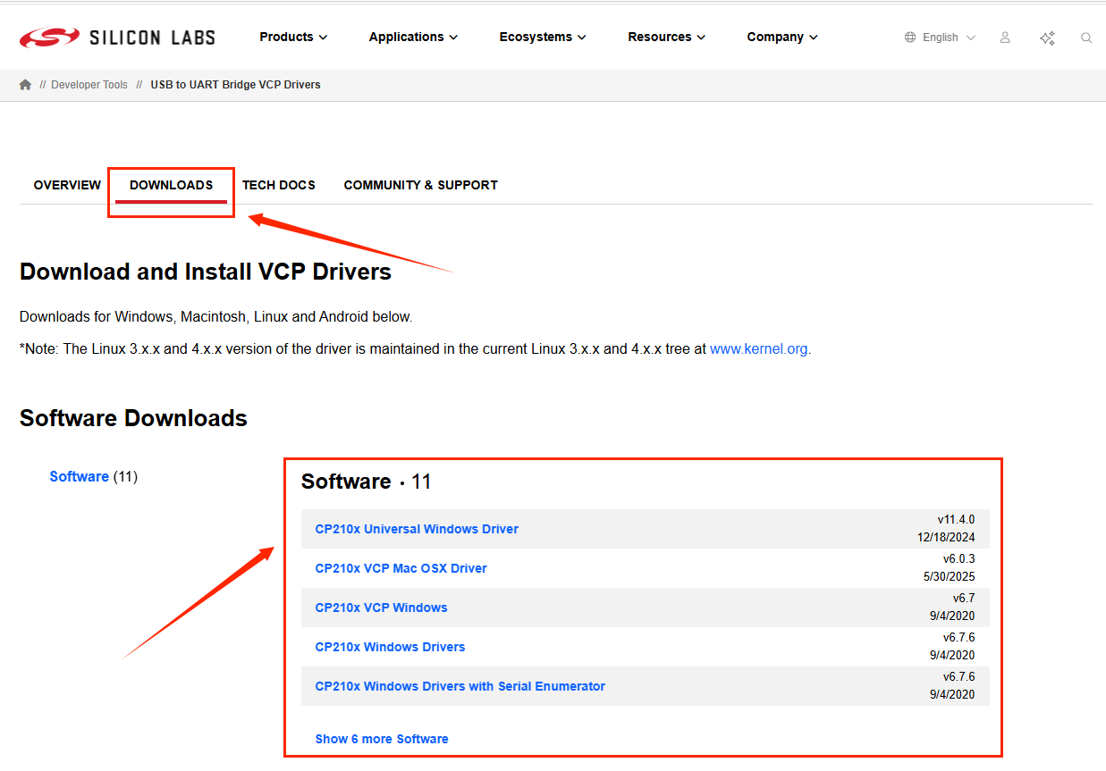
Double-click to install.
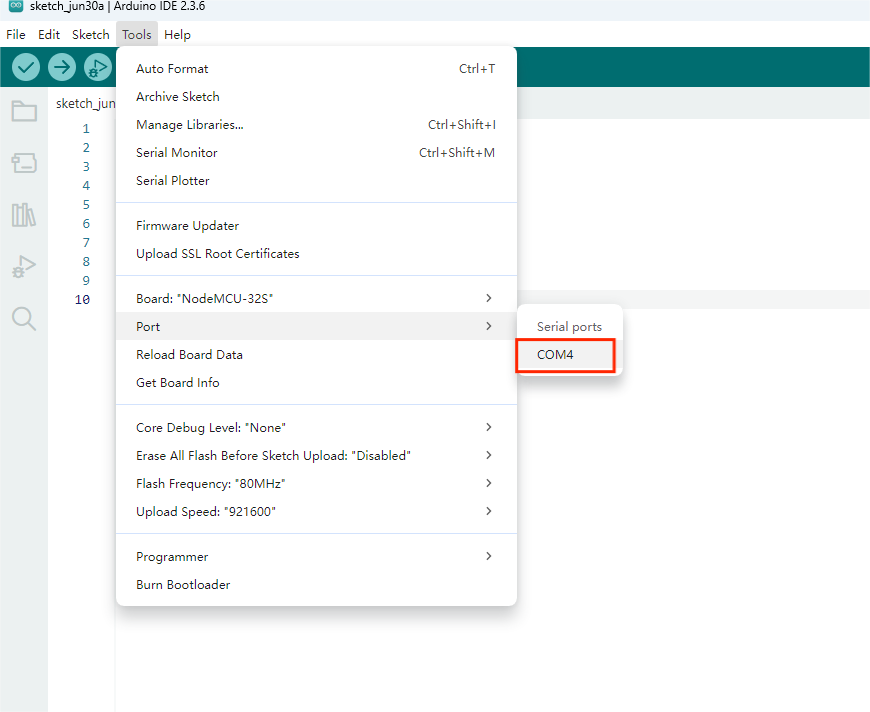
5. Select the board and port.
6.4.3Run Program
Open the project file /demo codes/Arduino_ESP32 using the Arduino IDE. Select the correct Board and Port based on your setup. Click Verify, and once the verification is successful, upload it to the module and observe the e-paper display.
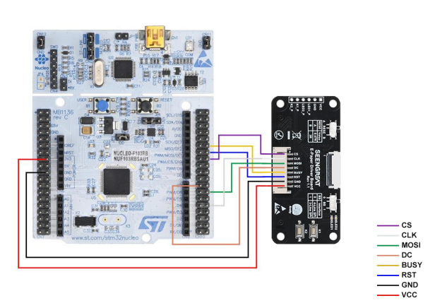
6.5 STM32 Platform
The example code is based on STM32F103RBT6 and the development board model is NUCLEO-F103RB.
6.5.1 Interface Configuration
E-paper Interface | STM32 Interface |
VCC | 3.3V |
GND | GND |
CS | PB12 |
CLK | PB13 |
MOSI | PB15 |
DC | PA8 |
RST | PA11 |
BUSY | PA12 |
Table 6-5 E-paper Display and STM32 Pin Definitions
The following diagram shows the wiring diagram between STM32 and the ink screen:
6.5.2 Run Program
Open the example in the directory /demo codes/STM32 using Keil uVision5 software. After compiling without errors, download it to the module and observe the e-paper display.
6.6 Image Digitization
6.6.1Image Creation
The screen supports 3 kinds of color display.They are black,white and red.The above 3 colors are standard colors.You can actually refer to the color table of the drawing software.When making pictures,you need to make a picture with 800x480 resolution into a bitmap that only contains black,white and red 3 colors.And save the picture in BMP or JPG format.
6.6.2 Mode Extraction
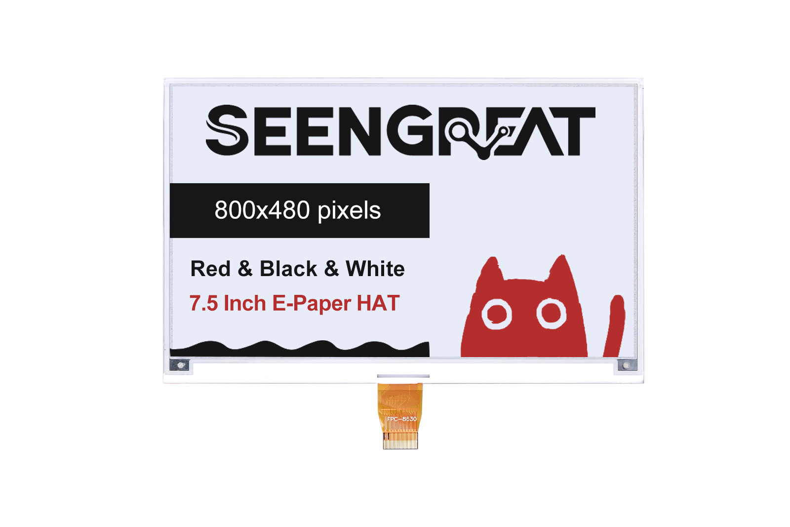
Figure 6-2
The provided software package includes Image2LCD for generating data arrays. Follow the steps below to achieve the effect shown in Figure 6-2 (refer to Figure 6-3 for parameter settings):
1、Split the Image
Separate the original black-white-red image into two:
Black & White image
Red & White image
Perform the same conversion process for both.
2、Load the Image
Open the desired image in Image2LCD.
3、Output Data Type
Select: "C Array (*.c)"
4、Scan Mode
Choose: "Horizontal Scan"
5、Output Grayscale
Select: "Monochrome"
6、Set Resolution
Max Width: 800
Max Height: 480
Click the arrow button to confirm.
7、Additional Options
Leave the checkboxes unchecked (as shown in the example).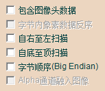
8、Click "Save" to store the converted array into a file with the ".c" extension. For an 800×480 resolution image, this will generate an image array with a size of 48,000 bytes.
9、Click "Finish Setup" , then click "Save"
  to export the converted array as a .c file.
10、Finally, two arrays will be obtained, one is the array for the black-and-white image, and the other is the array for the red-and-white image. Replace the corresponding arrays in the sample program code with the arrays in the file ".c".
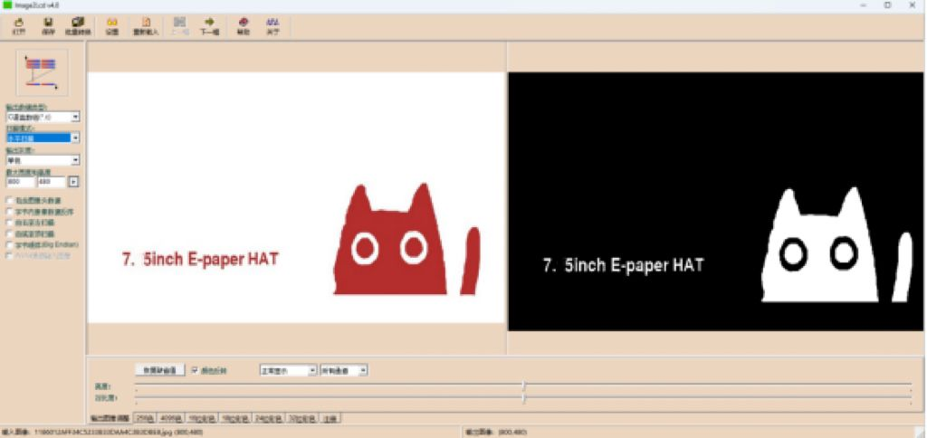
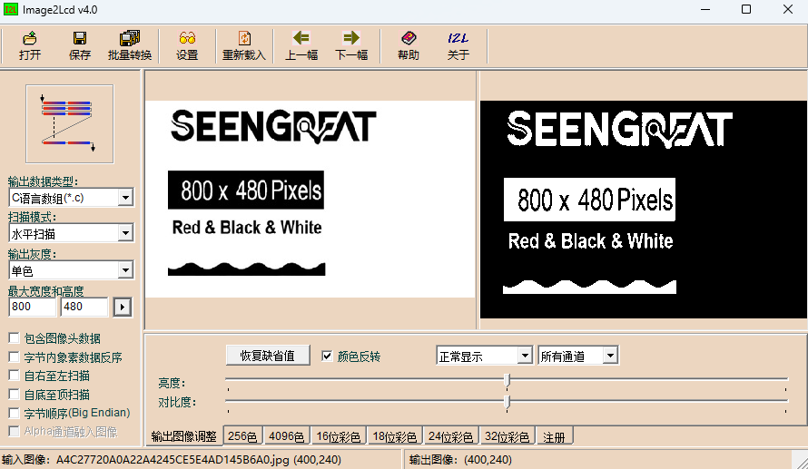
Figure 6-3 Parameter Setting Diagram
Ⅶ Information
1、 Schematic
2、 demo codes
3、 Data Sheet
4、 Image2Lcd
5、 Python Image Library
For additional features, users can visit the official website to learn more: