ⅠDescription

Figure 1-1 Main Image 1

Figure 1-2 Main Image 2
This product is a 2.9-inch 4-color ink screen, supporting black, white, yellow and red 4 color display.Its resolution is 384x168, using SPI communication mode, and supporting full refresh mode.Suitable for e-book readers, electronic price tags, industrial and logistics labels, digital signage, billboards, conference nameplates, electronic memos, etc.We provide example programs in C and Python for Raspberry Pi. A reserved SPI control interface allows easy integration with main control boards such as Arduino, STM32, and ESP32. We also offer example code for Arduino, STM32, and ESP32, which supports displaying images, English and numerical characters, and drawing points, lines, rectangles, and circles.
Ⅱ Features
- 2.9inch ink screen
- Support black, white, yellow, red 4 colors display, resolution: 384x168
- SPI interface, requiring fewer pins
- Onboard level-shifting chip, compatible with 3.3V and 5V microcontroller interfaces
- Reserved SPI communication interface for easy integration with main control boards such as Arduino, STM32, and ESP32
- Provides open-source example programs for Raspberry Pi, Arduino, STM32, and ESP32 development boards
Ⅲ Parameters
Size | 2.9 inch |
Pixels | 384 x 168 |
Display Colors | 4 colors: black, white, yellow, red |
Level-Shifting Chip | TXS0108EPWR |
Signal Interface | SPI |
Power Supply Voltage | 3.3V/5V |
Pixel Spacing | 0.176mm x 0.176mm |
Full Refresh | 20s |
Display Direction | Horizontal and Vertical |
Operating Temperature | 0℃-40℃ |
FPC Interface | 0.5mm pitch 24 Pin |
Refresh Power Consumption | 9.9mW |
Standby Power Consumption | 0.003mW |
Exterior Dimensions | 83mm x 36.9mm |
Display Area | 67.58mm x29.57mm |
Explanation of the refresh process (refresh time: the entire process from the beginning of the screen action to the stabilization of the screen):
Full Refresh: During the refresh process, the screen will flash many times.
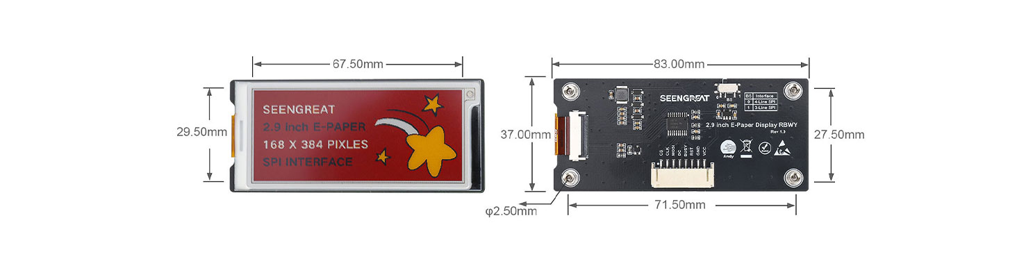
Figure 3-1 Dimensions
Ⅳ Resource Overview
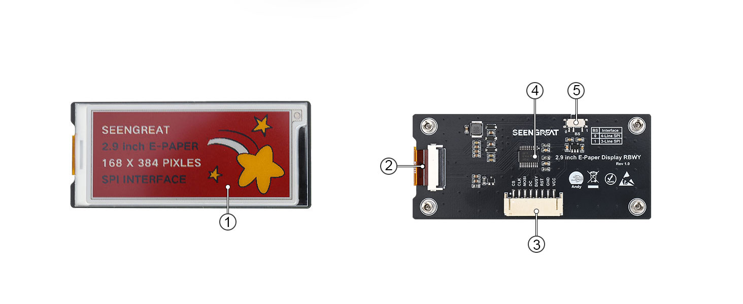
Figure 4-1 Driver Board Resource Overview
① 2.9-inch black-white-yellow-red 4-color ink screen
② E-paper screen connector
③ SPI control interface connector
④ Level-shifting chip TXS0108EPWR
⑤ SPI lines count selection switch(default is "0" position)
Ⅵ Usage
All the demo codes provided by this product are based on the 4-wire SPI mode, so the BS selection switch on the back of the board is set to "0" by default.
6.1 Interface Configuration
E-paper Interface SPI VCC 3.3V/5V GND Power ground RST External reset pin (low level reset) BUSY Busy status output pin D/C Data/Command control pin (high level for data, low level for command) MOSI SPI communication MOSI pin CS SPI chip select pin (active low) CLK SPI communication SCK pin
6.2 Raspberry Pi Platform
In order to be compatible with the bullseye and bookworm systems, this sample code is divided into wiringpi library version and lgpio library version, where the bullseye system uses the wiringpi library version, and the bookworm system uses the lgpio library version.
6.2.1 Interface Configuration
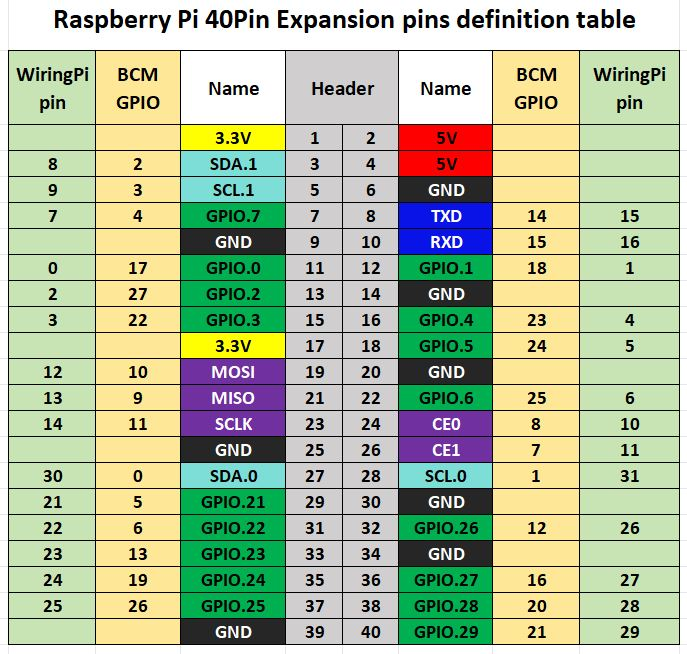
Figure 6-1 Raspberry Pi interface diagram
The following figure shows the wiring diagram between the Raspberry Pi and the ink screen:

The example programs for the Raspberry Pi board use the BCM numbering for pin definitions with the lgpio library and the wiringpi numbering with the wiringpi library. The pin wiring definitions for the Raspberry Pi board are as shown in the table below:
| E-paper Interface (E-paper Connector) | Pin Function | BCM Numbering | wiringpi Numbering |
| VCC | 3.3V | ||
| GND | GND | ||
| BUSY | Busy Signal Pin | 24 | 5 |
| RSTN | Reset | 17 | 0 |
| D/C | Command/Data Select | 25 | 6 |
| SDA | SPI Data Out/Slave In | 10 | 12 |
| SCL | SPI Clock | 11 | 14 |
| CSB | SPI Chip Select | 8 | 10 |
| LED1 | 4 | 7 | |
| LED2 | 18 | 1 | |
| K1 | 27 | 2 | |
| K2 | 22 | 3 |
Table 6-1 Driver Board and Raspberry Pi Pin Definitions
6.2.2 Library Installation
1. Wiringpi Library Installation
sudo apt-get install wiringpi
wget https://project-downloads.drogon.net/wiringpi-latest.deb
Upgrade Raspberry Pi 4B Version:
sudo dpkg -i wiringpi-latest.deb
gpio -v
If version 2.52 appears, it indicates that the installation has been successful.
- For the Bullseye branch system, use the following command:
git clone https://github.com/WiringPi/WiringPi
cd WiringPi
. /build
gpio -v
Running "gpio -v" will show version 2.70. If it doesn't appear, it means there is an installation error.
If an error message "ImportError: No module named 'wiringpi'" appears when running a sample program in Python version, run the following command:
- For Python 2.x version
pip install wiringpi - For Python 3.x version
pip3 install wiringpi
Note: If the installation fails, you can try the following compiled installation.
git clone --recursive
https://github.com/WiringPi/WiringPi-Python.git
Note: The --recursive option can automatically pull submodules. Otherwise, you need to download them manually.
Enter the newly downloaded WiringPi-Python folder and use the following commands to compile and install:
- For Python 2.x version
sudo python setup.py install- For Python 3.x version
sudo python3 setup.py installIf the following error occurs:

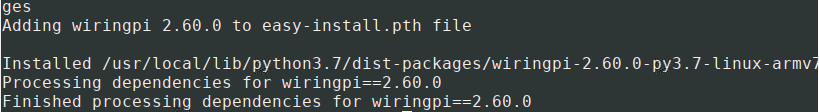
In this case, enter the command sudo apt install swig to install SWIG. After completing the installation, run sudo python3 setup.py install to compile and install. If you see similar information, it indicates that the installation was successful.
2. lgpio Library Installation
For the Bookworm system, the example programs use the lgpio library. The installation command for this library is:
wget https://github.com/joan2937/lg/archive/master.zip
unzip master.zip
cd lg-master
Make
sudo make install
3. Python Library Installation
The example program uses the Python3 environment. To run the Python example program, you need to install the PIL, numpy, and spidev libraries. Enter the following commands to install them:
Enter the following commands to install them:
sudo apt-get install python3-pil
sudo apt-get install python3-numpy
sudo apt-get install python3-pip
sudo pip3 install spidev
6.2.3 Enable the Communication Interface
sudo raspi-configEnable the SPI Interface:
Interfacing Options->SPI->YesCheck the enabled SPI devices:
ls /dev/spi*This will print: "/dev/spidev0.0" and "/dev/spidev0.1"
6.2.4 ExampleCode
1. Python Version Example
Using the lgpio library as an example, navigate to the /demo codes/raspberry_pi/lgpio/python directory.
sudo python3 gui_demo.pyAfter entering the above commands, you can observe the e-paper display.
2. C Version Example
Using the lgpio library as an example, navigate to the /demo codes/raspberry_pi/lgpio/c directory:
sudo make clean
sudo make
sudo ./main
After entering the above commands, you can observe the e-paper display.
6.3 Arduino Platform
6.3.1 Interface Configuration
Table 6-2 shows the wiring definitions between the Arduino Mega and the e-paper display:
E-paper Interface | Arduino Mega |
VCC | 5V |
GND | GND |
CS | D53 |
CLK | D52 |
MOSI | D51 |
DC | D8 |
RST | D9 |
BUSY | D10 |
Table 6-2 E-paper Display and Arduino Mega Pin Definitions
The following diagram shows the wiring diagram between the Arduino Mega and the ink screen:
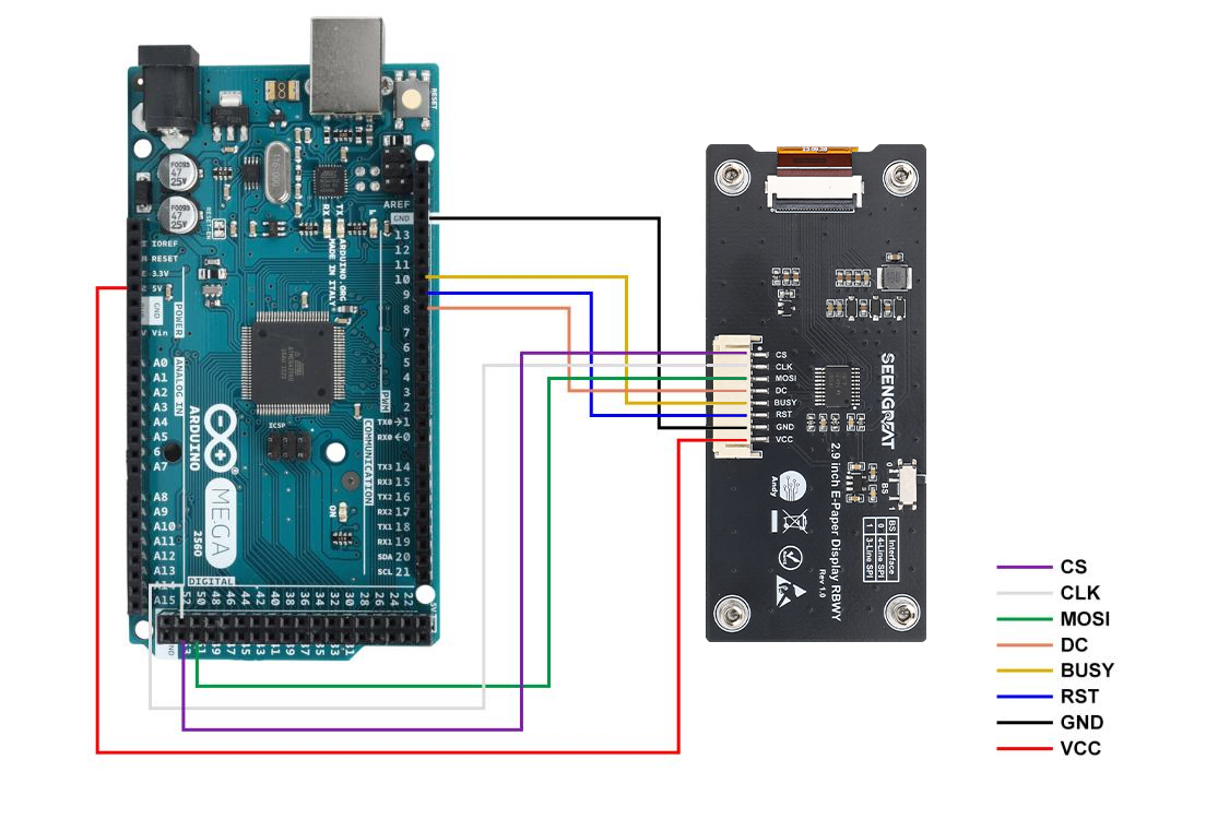
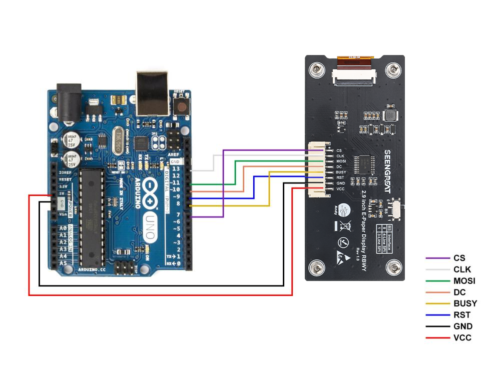
Table 6-3 E-paper Display and Arduino UNO Pin Definitions:
E-paper Interface | Arduino UNO |
VCC | 5V |
GND | GND |
CS | D7 |
CLK | D13 |
MOSI | D11 |
DC | D10 |
RST | D9 |
BUSY | D8 |
Table 6-3 E-paper Display and Arduino UNO Pin Definitions
The following diagram shows the wiring diagram between the Arduino UNO and the ink screen:
6.3.2 Arduino IDE Installation
1. Download the Arduino IDE installation package from the Arduino official website(Software | Arduino).
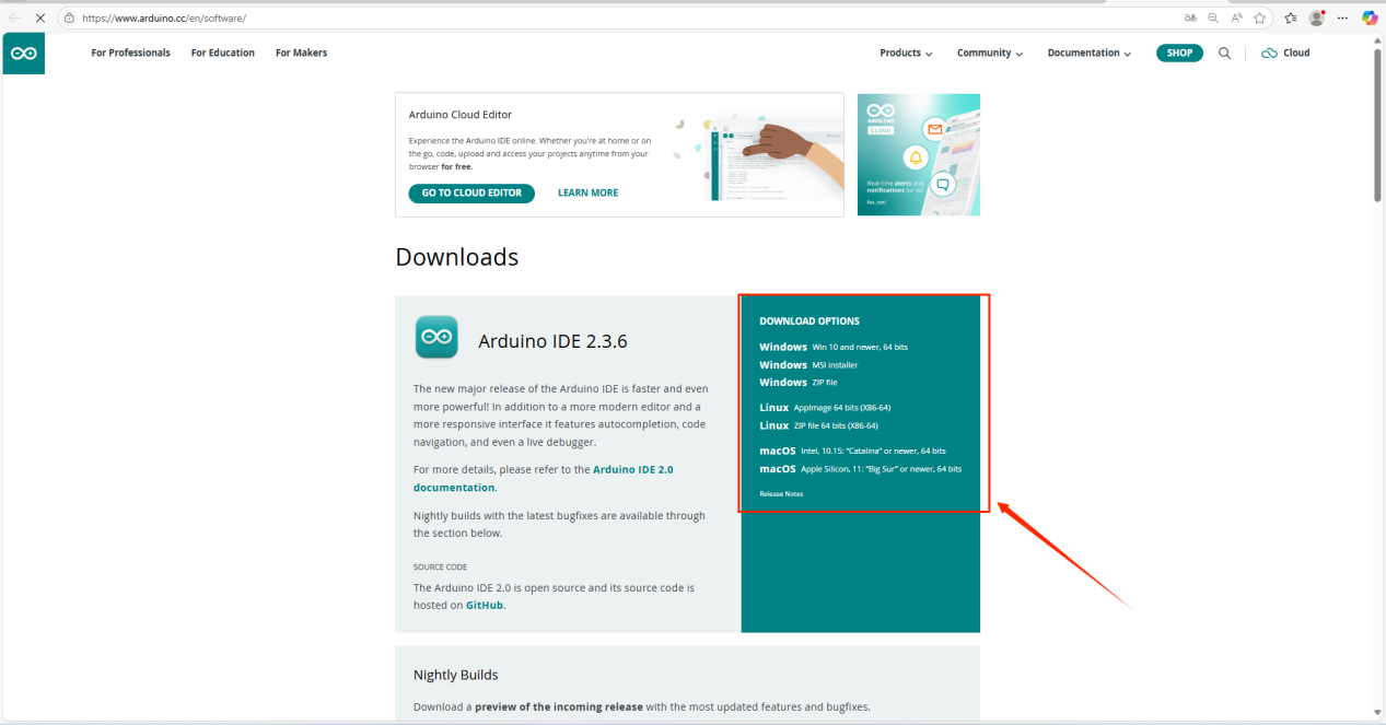
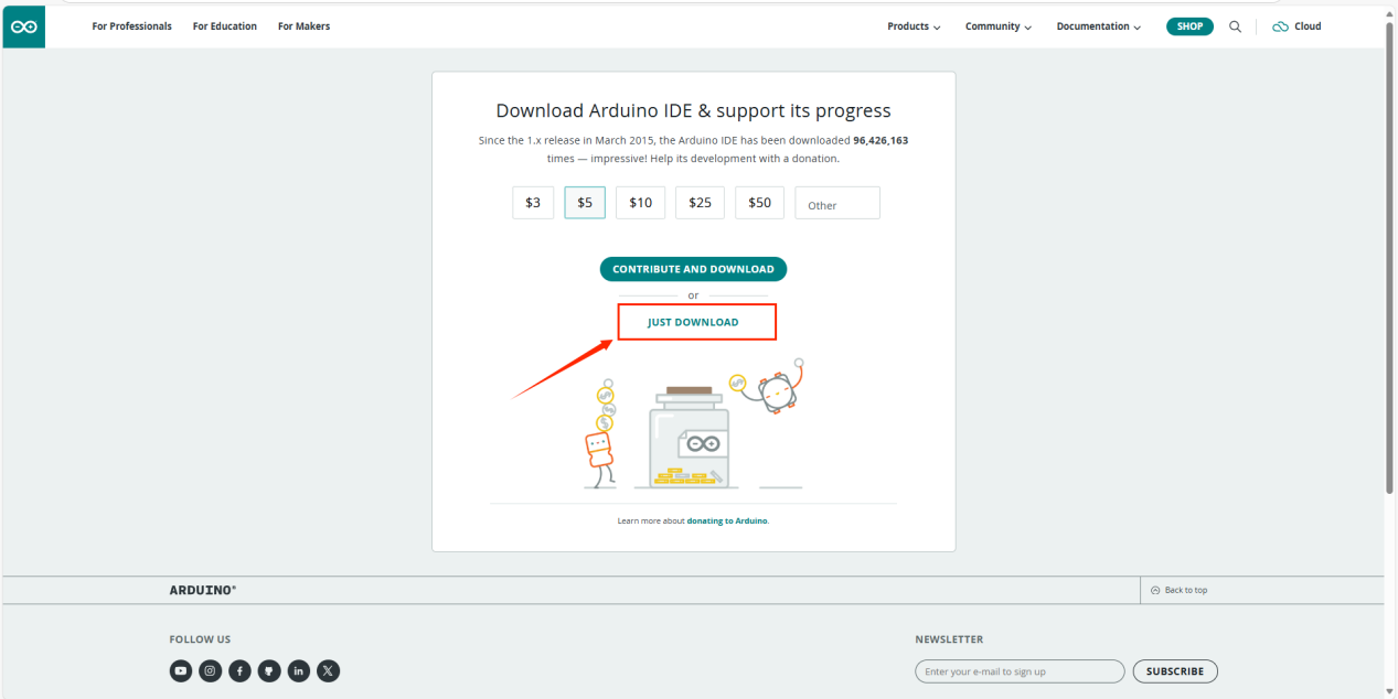
Select "JUST DOWNLOAD".
2. After the download is complete, click "Install".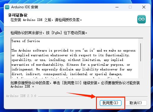
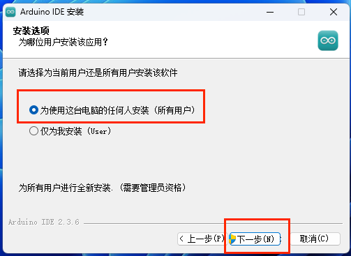
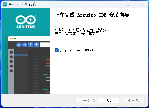
During the installation process, you will be prompted to install the driver. Just click "Install" to proceed.
3. Connect the Arduino development board.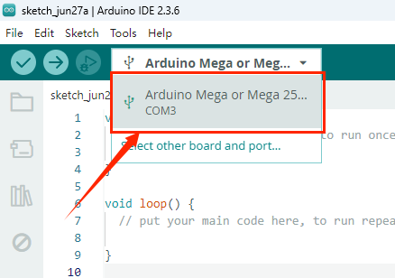
6.3.3 Run Program
Open the project file /demo codes/Arduino_MEGA/Arduino_MEGA.ino or /demo codes/Arduino_UNO/Arduino_UNO.ino in the Arduino IDE. Select the correct Board and Port based on your setup. Click Verify, and once the verification is successful, upload it to the module. Observe the e-paper display.
Note: Due to the small memory resources of Arduino, when using Arduino related routines, it is not possible to refresh and display multiple pictures at the same time.Please refresh as few images as possible, otherwise you will get a message that the memory is out.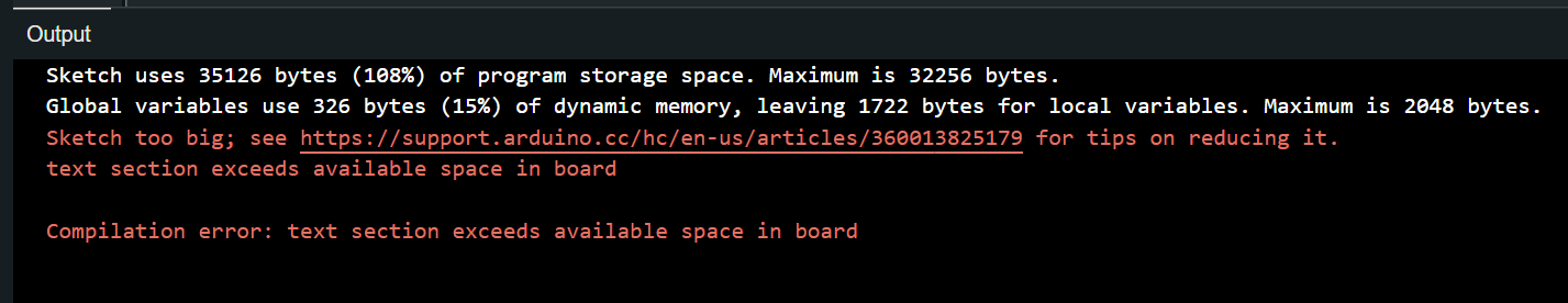
6.4 ESP32 Platform
The example program uses the ESP32 module ESP32-WROOM-32E.(Model of the board in the IDE:NodeMCU-32S)
6.4.1 Interface ConfigurationE-paper Interface | ESP32 Interface |
VCC | 3.3V |
GND | GND |
CS | IO27 |
CLK | IO18 |
MOSI | IO23 |
DC | IO14 |
RST | IO33 |
BUSY | IO13 |
Table 6-4 E-paper Display and ESP32 Pin Definitions
The following figure shows the wiring diagram between ESP32 and the ink screen: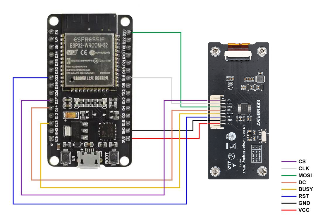
2. Configure the address of the ESP board manager.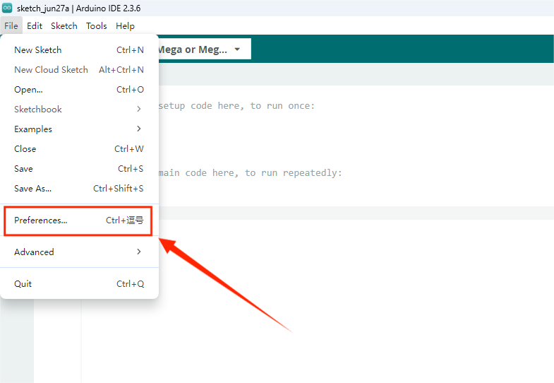
Paste the URL below into the "Additional boards manager URLs".
https://dl.espressif.com/dl/package_esp32_index.json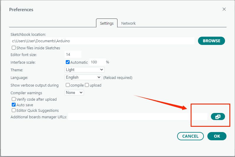
3. Download the board in the development board manager and wait for the installation to complete.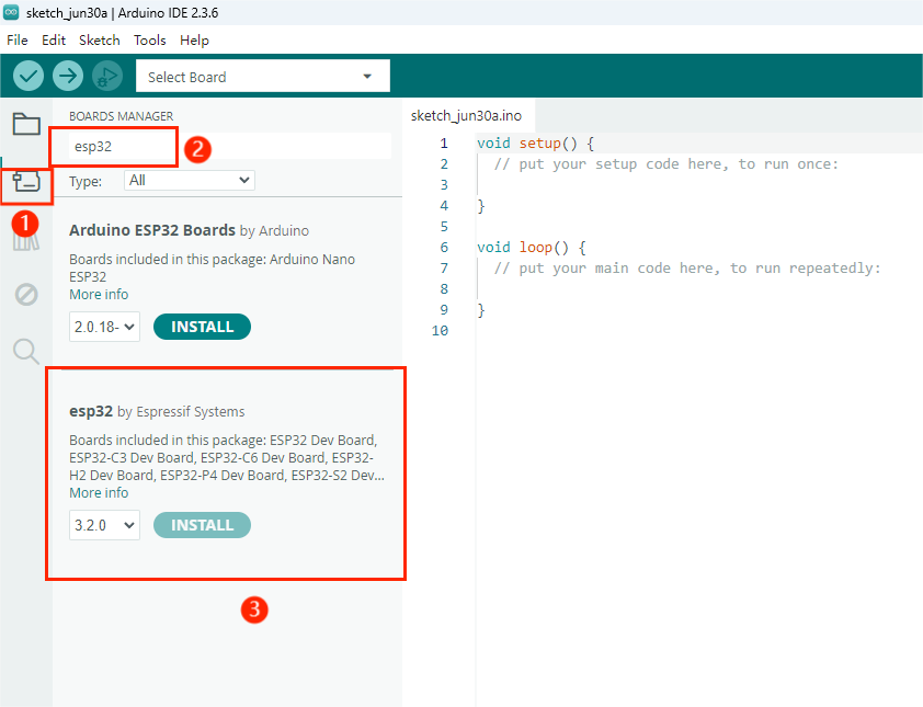
4. Download the driver.
Click on the following website link to download.
CP210x USB to UART Bridge VCP Drivers - Silicon Labs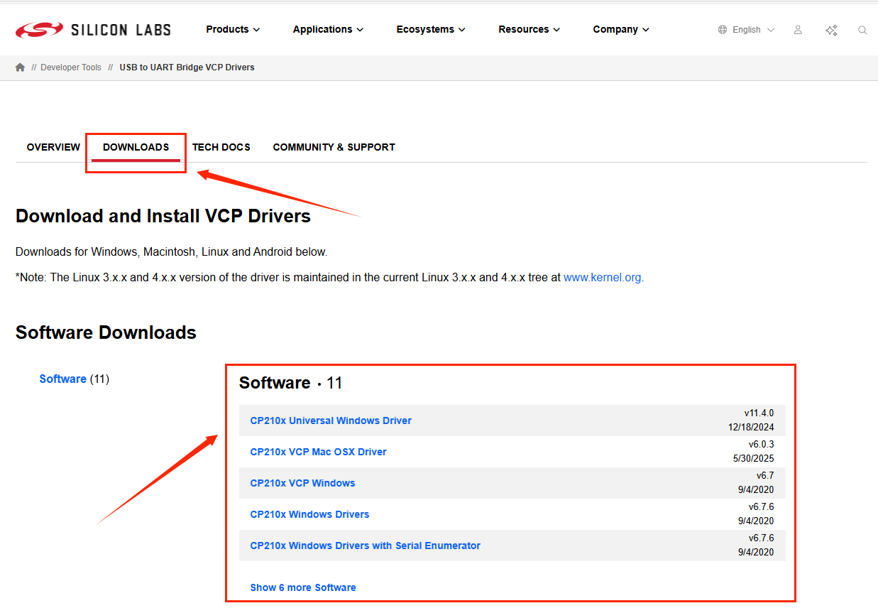
Double-click to install.
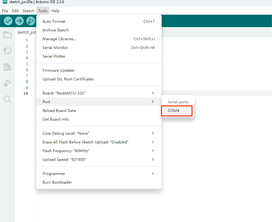
5. Select the board and port.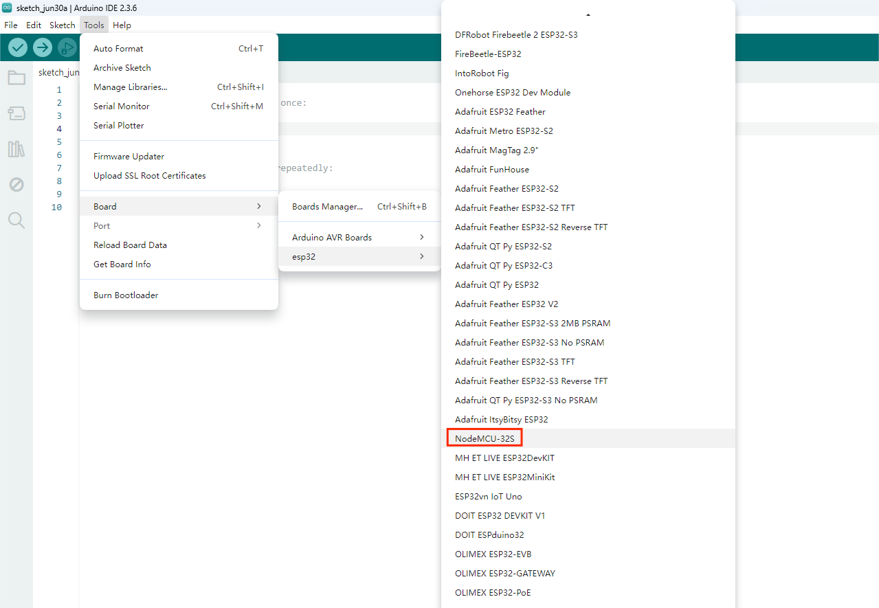
6.4.3 Run Program
Open the project file /demo codes/Arduino_ESP32 using the Arduino IDE. Select the correct Board and Port based on your setup. Click Verify, and once the verification is successful, upload it to the module and observe the e-paper display.
6.5 STM32 Platform
The example code is based on STM32F103RBT6 and the development board model is NUCLEO-F103RB.
6.5.1 Interface Configuration
E-paper Interface | STM32 Interface |
VCC | 3.3V |
GND | GND |
CS | PB12 |
CLK | PB13 |
MOSI | PB15 |
DC | PA8 |
RST | PA11 |
BUSY | PA12 |
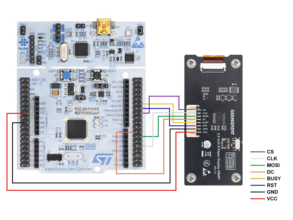
Table 6-5 E-paper Display and STM32 Pin Definitions
The following diagram shows the wiring diagram between STM32 and the ink screen:
6.5.2 Run Program
Open the project file /demo codes/Arduino_ESP32 using the Arduino IDE. Select the correct Board and Port based on your setup. Click Verify, and once the verification is successful, upload it to the module and observe the e-paper display.
6.6 Image Digitization
Please refer to the link:Image Digization