I Product Overview
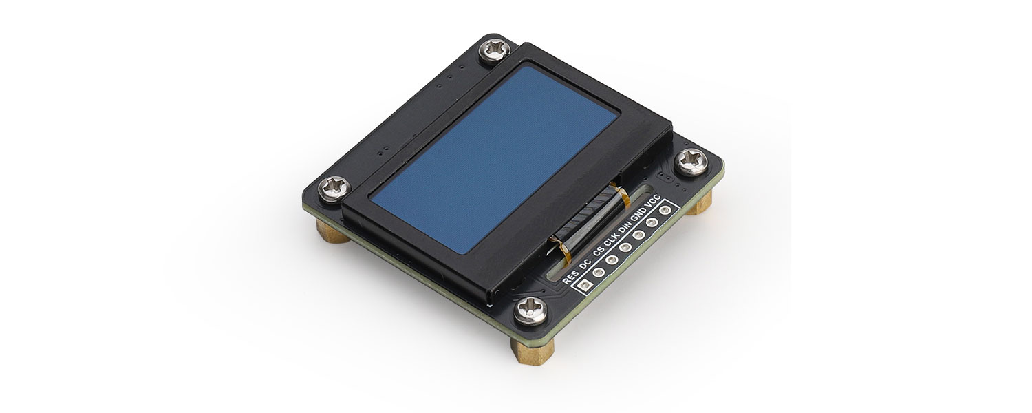
1.3inch OLED display128 x 64 pixelsBlack and whiteSupports SPI/ I2C communication
This product is a versatile 1.3-inch OLED display expansion module powered by the SH1106 controller, featuring 128x64 resolution. Designed for ultimate flexibility, it incorporates a unique slide switch enabling seamless transitions between SPI and I²C communication modes, along with I²C address configuration via a single resistor. Compatible with various popular development boards including Raspberry Pi series, Arduino, STM32, and ESP32, it integrates effortlessly into your projects.
We provide comprehensive sample code for Raspberry Pi (C/Python), Arduino, and STM32 platforms. These libraries empower you to draw points, lines, rectangles, and circles, with full support for displaying alphanumeric characters and images. Experience the convenience of a truly adaptive display solution that simplifies prototyping and development.
II Product Features
- 1.3-inch OLED display with 128×64 pixel resolution
- Supports SPI/I²C protocols with selector switch for seamless mode switching
- Onboard level shifter compatible with both 3.3V/5V MCU
- Open-source sample code
IIIProduct Parameters
Size | 38mm(Length) x 37mm(width) |
Pixels | 128 x 64 |
Display Color | black and white |
Voltage Translator | TXS0108EPWR |
Signal interface | SPI / I2C |
Supply voltage | 3.3V/5V |
OLED display area | 29.42×14.70 |
Driver chip | SH1106 |
IV Product Usage
All sample code for this product is written for SPI mode, so the switch on the back of the development board is preset to the "SPI" position. To use I2C mode, please follow these steps:
Flip the selector switch on the back of the development board to the "I2C" position Modify use_mode 1 to use_mode 0 in the oled.h file.
This product offers two selectable I2C addresses. In I2C mode, address selection is controlled by the soldering position of the I²C address selection resistor. To modify the I²C address:
Choose the desired I²C address and reposition the resistor to the corresponding solder pads
Simultaneously adjust the ADDR parameter value in both oled.h and oled.c files
4.1 Module Resource Profile
Module Resource Profile is shown in the figure below:
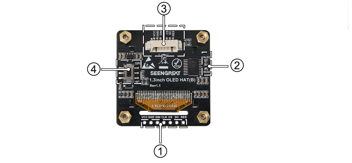
Figure 4-1 1.3inch OLED Display Resource Profile figure
① SPI/I2C control interface (2.54mm pitch pin header)
② IIC address selection resistor
③ SPI/I2C control interface (1.25mm pitch connector)
④ SPI/I2C selector switch
4.2 Raspberry Pi Wiring Definition
Since the bookworm system no longer supports the wiringpi library, the example program for this system uses the lgpio library, and for the bullseye system, the wiringpi library version of the example program can be used.
The bullseye system example program for the Raspberry Pi uses the pin definitions number in wiringPi, and the bookworm system uses the pin definition of the BCM number. The definition of the wiring with the Raspberry Pi motherboard is shown in the following table:
OLED display | WiringPi number | BCM number |
VCC | 3.3V | |
GND | GND | |
DIN | SPI:P12 / I2C:P8 | SPI:D10 / I2C:D2 |
CLK | SPI:P14 / I2C:P9 | SPI:D11 / I2C:D3 |
CS | P10 | D8 |
D/C | P6 | D25 |
RST | P0 | D17 |
Table 4-1 Definition of OLED display and Raspberry Pi pin
4.3 Arduino Wiring Definition
Table 4-2 is the wiring definition between Arduino Mega and OLED display:
OLED display | Arduino Mega |
VCC | 5V |
GND | GND |
DIN | SPI:D51 / I2C:SDA1 |
CLK | SPI:D52 / I2C:SCL1 |
CS | D10 |
D/C | D9 |
RST | D8 |
Table 4-2 Pin definition of OLED display and Arduino Mega
Table 4-3 is the wiring definition between Arduino Uno and OLED display:
OLED display | Arduino Uno |
VCC | 5V |
GND | GND |
DIN | SPI:D11 / I2C:SDA |
CLK | SPI:D13 / I2C:SCL |
CS | D10 |
D/C | D9 |
RST | D8 |
Table 4-3 Pin definition of OLED display and Arduino Uno
4.4 STM32 Wiring Definition
The STM32 module used in this example program is STM32F103C8T6.The product wiring definition is shown in Table 4-4 below:
OLED display | STM32 |
VCC | 3.3V |
GND | GND |
DIN | SPI / I2C:PA7 |
CLK | SPI / I2C:PA5 |
CS | PB4 |
D/C | PA3 |
RST | PA2 |
Table 4-4 Pin definition of OLED display and STM32
4.5ESP32 Wiring Definition
The ESP32 module used in this example program is ESP32-WROOM-32E.The product wiring definition is shown in Table 4-5 below:
OLED display | ESP32 |
VCC | 3.3V |
GND | GND |
DIN | SPI:IO23/ I2C:IO21 |
CLK | SPI:IO18/ I2C:IO22 |
CS | IO25 |
DC | IO26 |
RST | IO33 |
Table 4-5 Pin definition of OLED display and ESP32
Ⅴ Appendixes
5.1 Product Precautions and Maintenance
5.1.1 Precautions
- Do not plug or unplug modules while they are powered on.
- Follow all warnings and guidelines provided on the product.
- Keep the product dry. In case of accidental splashing or immersion in any liquid, immediately disconnect the power and thoroughly dry the product.
- Ensure proper ventilation and heat dissipation in the operating environment to avoid damage to components due to high temperatures.
- Do not use or store the product in dusty or dirty environments.
- Avoid using the product in environments with frequent temperature changes to prevent condensation damage to the components.
- Handle the product gently, as dropping, hitting, or severe shaking may damage the circuits and components.
- Do not clean the product with organic solvents or corrosive liquids.
- Do not attempt to repair or dismantle the product by yourself. In case of any malfunction, please contact our company for repairs. Unauthorized repairs may damage the product, and any resulting damage will not be covered under warranty.