Compact UPS Power Module for Raspberry Pi Zero with Solar Input and Smart Battery Management
This board is a dedicated uninterruptible power supply (UPS) solution designed specifically for the Raspberry Pi Zero series, with a focus on safety, intelligence, and reliability. It integrates a suite of advanced power management components, including:
- A battery protection IC for safe charging and discharging
- An LED fuel gauge chip for real-time battery level indication
- A high-precision battery monitoring chip supporting I2C communication
- A multi-functional charge management chip that enables simultaneous charging and discharging
The board provides a stable 5V regulated output, ensuring reliable operation for your Raspberry Pi even during power interruptions.
Additionally, it includes an onboard solar energy management chip, supporting 5V–24V solar input, expanding the possibilities for off-grid or renewable energy applications.
From robust hardware safeguards to developer-friendly features, this module is more than just a power supply—it's a versatile tool that empowers innovation while maintaining a compact footprint.
Despite its small size, it delivers impressive endurance. For example, with a 1500mAh battery and no external peripherals connected, it can remain on standby for approximately 9 hours. This compact and portable design makes it an excellent choice for mobile or remote-edge Raspberry Pi projects.
Product Features
- Plug-and-Play Compatibility
Fully compatible with the Raspberry Pi Zero series—no driver installation or configuration required. Just plug in and power up.
- True Uninterruptible Power Supply
Equipped with a smart charge management chip supporting path control for seamless switching between charging and discharging—ensures stable 5V output without power drops.
- Wide-Range Solar Input with MPPT
Supports 5V–24V photovoltaic input, with onboard MPPT algorithm for intelligent tracking of the maximum power point, maximizing solar charging efficiency.
- Onboard Battery Level Indicator
- Real-Time Power Monitoring & Stable Output
Product Specifications
Specification | Details |
Model | Pi Zero UPS HAT (B) |
Onboard Chips | TPS61088, ETA6003, CN3791, INA219, HM1160 |
Communication Interface | I²C |
Power Input | USB: 5V / Solar: 5V–24V |
Output Voltage | 5V |
Mounting Hole Diameter | 2.5mm |
Dimensions | 65mm (L) × 30mm (W) |
Resource Overview

① Power & Communication Pins ② Boost Converter Chip for 5V Output
③ Lithium Battery Charging Chip ④ Type-C Connector: Supports 5V input
⑤ Solar Charging Connector: Connects to solar panels via terminal block; be sure to observe correct polarity ⑥ Solar Charging Chip ⑦ Slide Switch: When switched to ON, the power pin outputs 5V; when OFF, 5V output is disabled
⑧ MPPT Voltage Setting DIP Switch: Used to configure the MPPT charging voltage according to the solar input, improving charging efficiency
⑨ Onboard Battery Level Indicator LEDs
⑩ Charging Indicator LED: CHRG LED lights up when power is supplied via Type-C or DC input ⑪ M2.5 Mounting Hole ⑫ 2-Pin Lithium Battery Connector
Dimensions

Hardware Assembly Guide
- Before Assembly: Confirm the power slide switch on the expansion board is set to the "OFF" position. This disconnects the 5V output.
- Align & Secure: Precisely align the Raspberry Pi Zero main board with the power & communication pins of the expansion board. Use the provided M2.5 copper standoffs and screws to fasten diagonally in two stages, ensuring there is no misalignment or gaps between the main board and the expansion board.
- Connect Battery: Only after mechanical fastening is complete, connect the lithium battery to the board.
- Power On: Finally, smoothly push the power switch to the "ON" position. Observe the onboard battery level indicator LEDs, which will display the current battery charge status.
Important Notes:
- Battery Activation: When connecting the battery for the first time or replacing it, you must first charge the battery to activate its protection circuit. Output will only be available when the power switch is in the "ON" position.
- Prevent Short Circuits: Always set the power switch to "OFF" before assembly to prevent potential short circuits during the process.
- Load Limitations: The output current is approximately 1.8A when the battery is fully charged. As the battery voltage decreases, the output current will also reduce. Connecting an excessively large load may lead to unstable boosting and cause the Raspberry Pi to repeatedly restart.
- Polarity & Chargers: Always observe battery polarity when connecting; ensure it is correct. Do not use inferior or unapproved chargers/charging boards to charge the lithium battery.
- Storage: Store battery products properly in a dry and safe environment.
- Solar Charging: When using solar charging, ensure the positive and negative terminals of the input are connected correctly. If the solar panel does not charge after connection, please verify the input polarity.
Features Overview
This section details the key functionalities and specifications of the board:
1. Battery Level Indication: Features five onboard LEDs. Four LEDs provide a four-segment (25%/50%/75%/100%) display for clear, intuitive monitoring of current battery status.
- Charge Mode: The red CHRG indicator LED activates, and the power LEDs illuminate progressively according to charging progress.
- Discharge Mode: When the main switch is ON, the remaining battery power is dynamically displayed. When OFF, the output is disconnected (and LEDs turn off).
- The on-board battery capacity indicator LEDs reflect the current battery voltage level. The display range is referenced in the table below:
Voltage Range (V) | LED1 | LED2 | LED3 | LED4 |
3.87V-4.2V | On | On | On | On |
3.7V-3.87V | On | On | On | Off |
3.55V-3.7V | On | On | Off | Off |
3.4V-3.55V | On | Off | Off | Off |
2. Seamless Raspberry Pi Zero Integration: Utilizes a spring pogo pin connection design for easy and secure compatibility with the Raspberry Pi Zero series mainboards.
3. Advanced Power Management: Incorporates an onboard lithium battery charging chip with path management, a solar charging chip, and a boost chip. This setup supports dynamic path management and provides a stable 5V voltage output.
4. Comprehensive Battery Protection: Equipped with an onboard battery protection circuit that includes safeguards against overheating, overcurrent, overcharge, over-discharge, and short-circuits.
5. Real-Time Monitoring: Features an onboard INA219 battery monitoring chip that communicates via an I2C interface, allowing for real-time detection of the module's operational status.
6. Flexible Charging Inputs: Supports 5V input via USB charging and a 5V-24V input for solar charging.
- Important: The solar panel input and USB Type-C input cannot be used simultaneously to charge the battery.
8. MPPT Voltage DIP Switch Settings:
- Configuration: Only one DIP switch position is allowed to be set to "ON" at a time; all other positions must be "OFF."
- Voltage Selection: The MPPT voltage setting should be based on the specifications of your solar panel (with a focus on the panel's Vmp value, which is the maximum power point voltage).
- Basic Requirement: The solar panel's output voltage must be greater than the MPPT set voltage.
- Efficiency Optimization: Charging efficiency is maximized when the solar panel's Vmp output voltage is closer to the MPPT set voltage.
Please refer to the table below for specific charging voltage settings:
DIP Switch | Bit:6 | Bit:5 | Bit:4 | Bit:3 | Bit:2 | Bit:1 | Set Voltage |
status | OFF | OFF | OFF | OFF | OFF | ON | 5V |
OFF | OFF | OFF | OFF | ON | OFF | 6V | |
OFF | OFF | OFF | ON | OFF | OFF | 9V | |
OFF | OFF | ON | OFF | OFF | OFF | 12V | |
OFF | ON | OFF | OFF | OFF | OFF | 18V | |
ON | OFF | OFF | OFF | OFF | OFF | 24V | |
Explanation:The value set for the charging voltage needs to be less than orequal to the input charging voltage.If you set the value of the "MPPT SET"DIP switch to 5V,you can input charging voltages ranging from 5 to 24VHowever,the charging efficiency is highest when the charging voltage is setto 5V.If the"MPPT"DIP is set to 12V,you can input charging voltagesranging from 12 to 24V,with the highest efficiency achieved at a chargingvoltage of 12V.The same method applies to other settings. | |||||||
9. Battery Charging Power
- Charging Power Dynamics: The lower the battery's charge level, the higher the charging power.
- USB Charging: The maximum charging power via USB is 5W.
- Solar Charging: Higher solar panel output power results in greater charging power.
- Maximum Solar Charging: When the solar panel output is sufficient and the battery charge is low, the maximum charging power can reach approximately 5W.
Raspberry Pi I2C Configuration
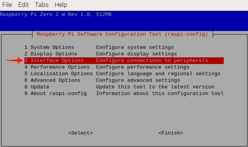
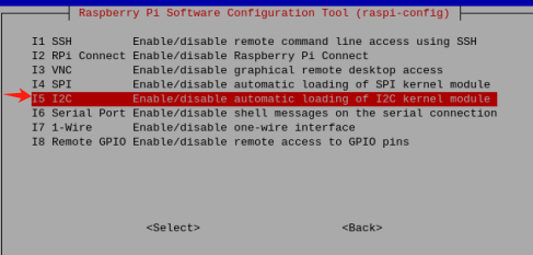
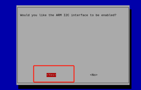
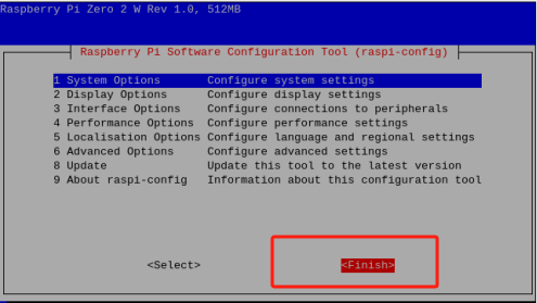
To configure I2C on your Raspberry Pi, launch the system configuration to:
sudo raspi-config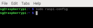 Enable the I2C interface:
 Interfacing Options -> I2C -> Yes
 Reboot the device
sudo rebootsudo i2cdetect -y -a 1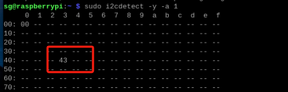
Sample Program Demonstration
Enter the downloaded sample program file directory, such as:
cd My Demo Files Directorpython INA219.pyThe window will print out the current battery voltage, current, and power. When the current shows a negative number, it means the battery is discharged: