 1
1RP2350-MINI(ETH) Ethernet Development BoardRP2350A Dual-core Dual-architecture ProcessorRaspberry Pi MicrocontrollerW5500 TCP/IP Ethernet Control Chip
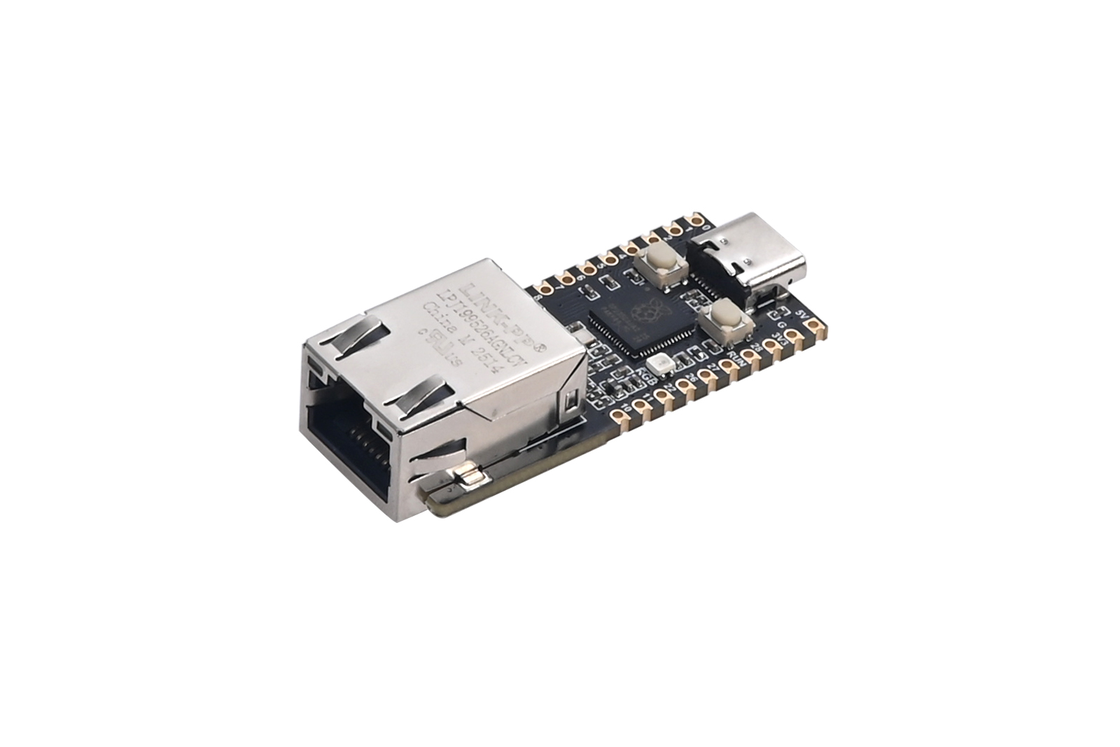
The RP2350-MINI(ETH) development board is developed using the Raspberry Pi dual-core dual-architecture microcontroller RP2350A and the W5500 Ethernet control chip. With a pin header design, it also has an extremely small PCB area, making it very convenient for users to directly weld and integrate it onto the self-designed baseboard. Meanwhile, they can also weld the pins with a pitch of 2.54mm and directly insert them onto the self-designed baseboard. The board also exposes a Type C port, RGB LEDs, a reset button, a BOOT button, and an RJ45 connector, which is convenient for users to develop and debug. This development board is highly suitable for maker projects, building automation control systems, small network devices, embedded system development, and DIY electronic products.
Product Features
- Dual-core Microcontroller: Powered by the RP2350A Raspberry Pi dual-core microcontroller, featuring either dual-core Arm Cortex-M33 or dual-core Hazard3 RISC-V processor running at 150MHz.
- The W5500 chip supports hardware TCP/IP protocols: TCP, UDP, ICMP, IPv4, ARP, IGMP, PPPoE.
- The W5500 has an internal 32KB buffer and supports up to 8 independent sockets for simultaneous communication.
- The W5500 supports auto-negotiation (10/100-Based full-duplex/half-duplex).
- USB Type-C Port: Supports USB 1.1 host and device, enabling drag-and-drop file downloads to large-capacity storage.
- Onboard Buttons and LEDs: Includes RUN reset button, BOOT button, and RGB LED WS2812,RJ45 connector.
- Rich Open-Source Resources: Supports C/C++ and MicroPython, with extensive documentation and example resources available for development.
Product Specifications
Parameter | Specification |
Supply Voltage | 5V (via Type-C or 5V pads on the through-hole) |
Dimensions | 50mm (L) x 20.32mm (W) |
Weight | 8.2g |
Resource Introduction
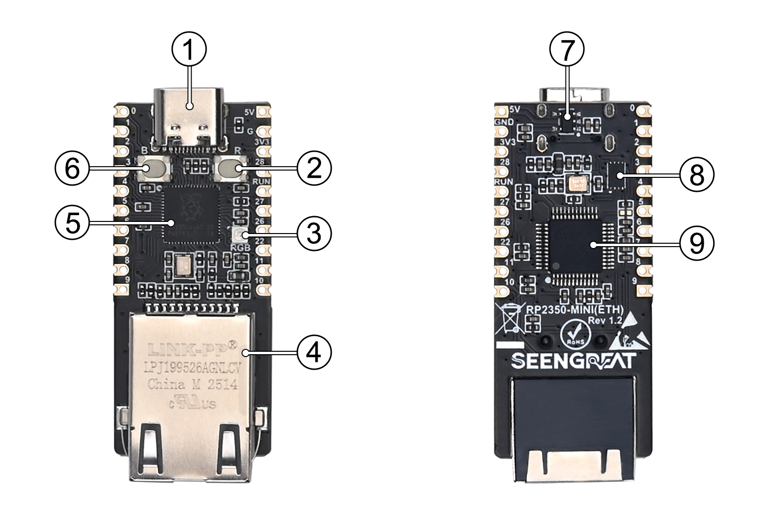 Figure 2-1
① Type-C Connector: Supports USB 1.1 host and device, can be used for program downloading.
② RUN Reset Button: Used to reset the board.
③ WS2812: Full-color RGB LED for visual indication.
④ RJ45 connector(with indicator LEDs):support 10/100-Based full-duplex/half-duplex.
⑤ RP2350A: Dual-core Arm Cortex-M33 or dual-core Hazard3 RISC-V processor running at 150MHz.
⑥ BOOT Button: Press and hold this button while powering on to enter download mode.
⑦ Linear Regulator ME6211C33M5G: Provides a 3.3V output with a maximum current output of 500mA.
⑧ W25Q32RVXHJQ: 4MB Nor-Flash for storage.
⑨ W5500:TCP/IP Ethernet control chip.
Usge
GPIO pins
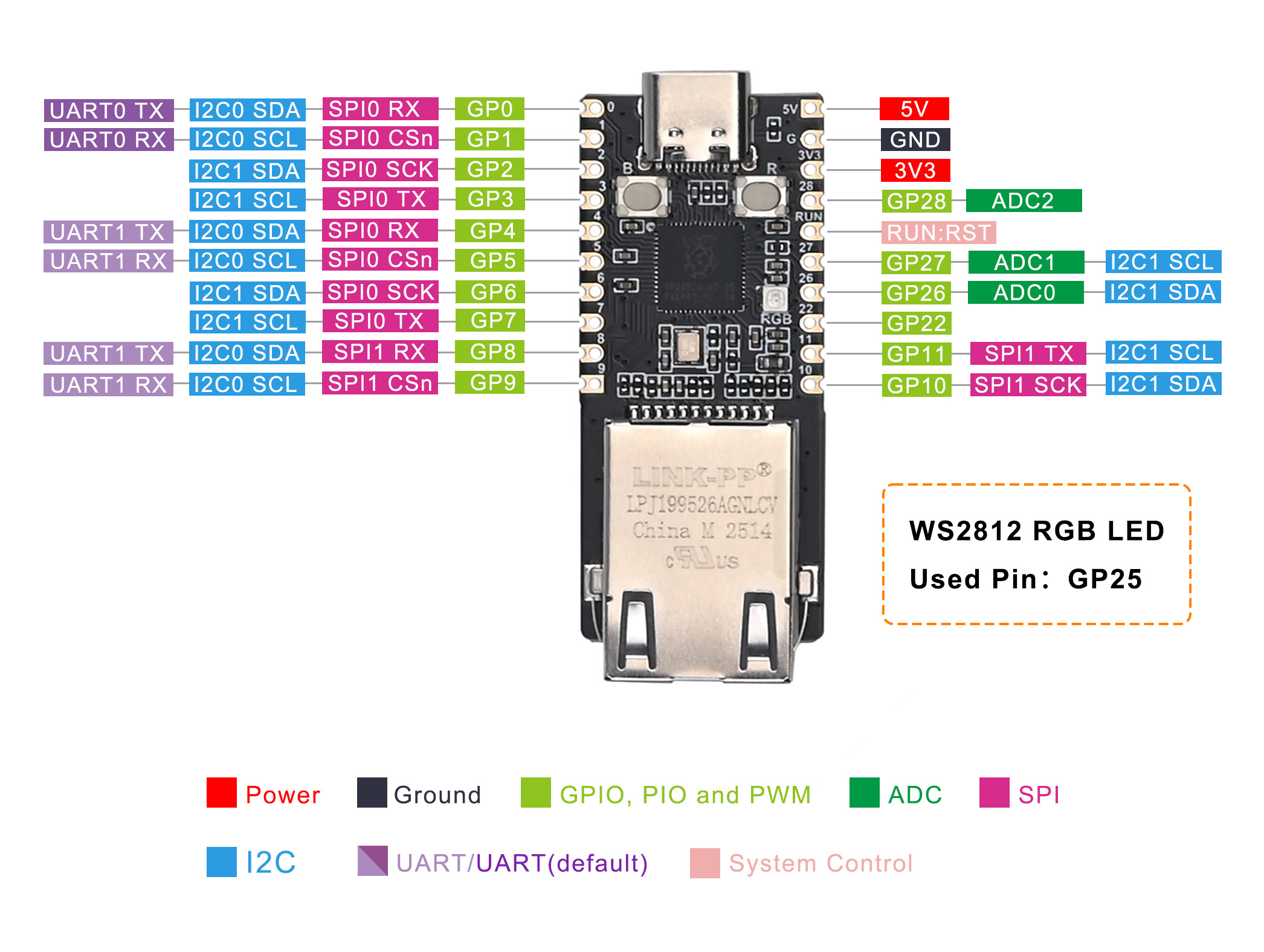 Figure 2-2
Example Program Description
This module provides example programs for four Ethernet communication modes: TCP Client, TCP Server, UDP Client, and UDP Server. This section will primarily explain the MicroPython versions of these examples; the C/C++ language versions are similar in concept, differing only in syntax.
The w5500.py file contains the low-level driver for the W5500 chip. It primarily defines registers and functions for register operations, which are then called by the application-layer code. For all network communication modes except udp_servers, socket_num is defaulted to 0, meaning only socket 0 is used. Users can modify this by changing self.socket_num = 0 within the class W5500: -> __init__: section of the w5500.py file.
The board's default factory setting runs the main.py file written in Python, which includes WS2812 display, TCP Server, and GPIO output functionalities. This program executes automatically upon power-up.
Note: All example codes can be downloaded from the Resources -> Example-programs section at the bottom of this page.
Below are the functions users may need to modify based on their specific network environment:
Gateway configuration
dat = bytearray([192, 168, 1, 1]) #python
eth.Write_Bytes(w5500.GAR, dat, 4)uint8_t dat[4] = {192, 168, 1, 1};//C/C++
W5500_writeBytes(GAR, dat, 4);Subnet mask configuration
dat = bytearray([255, 255, 255, 0])#python
eth.Write_Bytes(w5500.SUBR, dat, 4)uint8_t sub_mask[4] = {255, 255, 255, 0};//C/C++
W5500_writeBytes(SUBR, sub_mask, 4);MAC address setting
dat = bytearray([0x48, 0x53, 0x00, 0x57, 0x55, 0x00]) #python
eth.Write_Bytes(w5500.SHAR, dat, 6)uint8_t mac[6] = {0x48, 0x53, 0x00, 0x57, 0x55, 0x00}; //C/C++
W5500_writeBytes(SHAR, mac, 6);W5500 IP address setting
dat = bytearray([192, 168, 1, 101]) #python
eth.Write_Bytes(w5500.SIPR, dat, 4)uint8_t ip[4] = {192, 168, 1, 101}; //C/C++
W5500_writeBytes(SIPR, ip, 4);W5500 socket port number setting
eth.Write_SOCK_2_Byte(eth.socket_num, w5500.Sn_PORT, 5000)Or
W5500_writeSOCK2Byte(socket_num, Sn_PORT, 5000);Destination IP address setting (PC IP)
dat = bytearray([192, 168, 1, 12]) #your tcp server IP
eth.Write_SOCK_4_Byte(eth.socket_num, w5500.Sn_DIPR, dat)uint8_t server_ip[4] = {192, 168, 1, 18}; // your TCP server IP
W5500_writeSOCK4Byte(socket_num, Sn_DIPR, server_ip);Destination port number setting
eth.Write_SOCK_2_Byte(eth.socket_num, w5500.Sn_DPORTR, 5000)W5500_writeSOCK2Byte(socket_num, Sn_DPORTR, 5000);Python Example Program
Installing Thonny
Download and install Thonny from their official website:
Uploading Firmware
- With the RP2350-MINI(ETH) board powered OFF, press and hold the BOOT button (refer to ⑥ in Figure 2-1).
- Connect the board to your computer using a USB cable, then release the BOOT button.
- Your computer should now show a removable disk directory named "RP2350."
- Drag and drop the
RPI_PICO2-20241025-v1.24.0.uf2file from yourdemo codesdirectory into the "RP2350" disk.If you need the latest firmware,please visit the web:https://micropython.org/download/RPI_PICO2/ to download the latest version firmware
Using WS2812 Example
- Right-click the
ws2812.pyfile within thedemo codesdirectory and open it with Thonny. - In Thonny, navigate to Tools > Options > Interpreter.
- In the "Interpreter" dropdown, select "MicroPython (Raspberry Pi Pico)."
- Set the correct Port (COMx) – the port number (x) may vary depending on your computer.
- Click OK to confirm your settings.
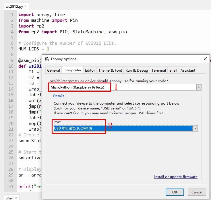
Figure 2-3
Then, click the "Run current script" button or press F5 to execute the script. You should see the onboard RGB LED illuminate in red, green, blue, and white, then turn off.
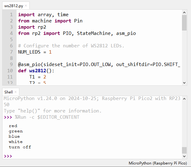
Figure 2-4
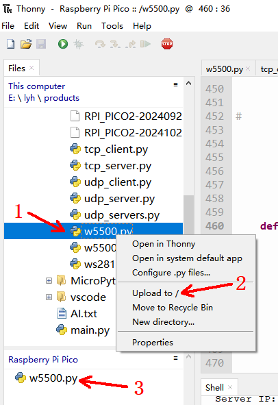
Uploading w5500.py
- In Thonny, go to View > Files.
- In the "Files" window, navigate to
demo codes > MicroPython. - Right-click on
w5500.py. - Select "Upload to /" from the context menu, as shown in Figure 2-5 below.
TCP Client Mode
The tcp_client.py file primarily enables the W5500 to function as a client.
The W5500_Config function handles the configuration of the W5500's gateway, subnet mask, MAC address, and IP address. Users should modify these parameters to match their specific network environment.
The Socket_Config function configures the socket channel parameters, including socket 0's port number, MSS (Maximum Segment Size) value, send/receive buffer sizes, the server's IP address (i.e., your computer's IP address), and the server's port number.
The main function executes the following sequence: initializes SPI, initializes the W5500, establishes the link, configures W5500 parameters, checks the gateway, and then continuously sends data to the server once a connection is successfully established.
Refer to Figure 2-6 for the connection diagram.
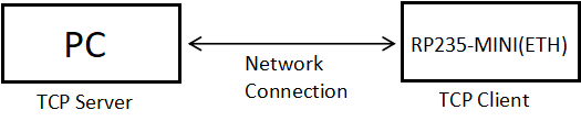
Figure 2-6
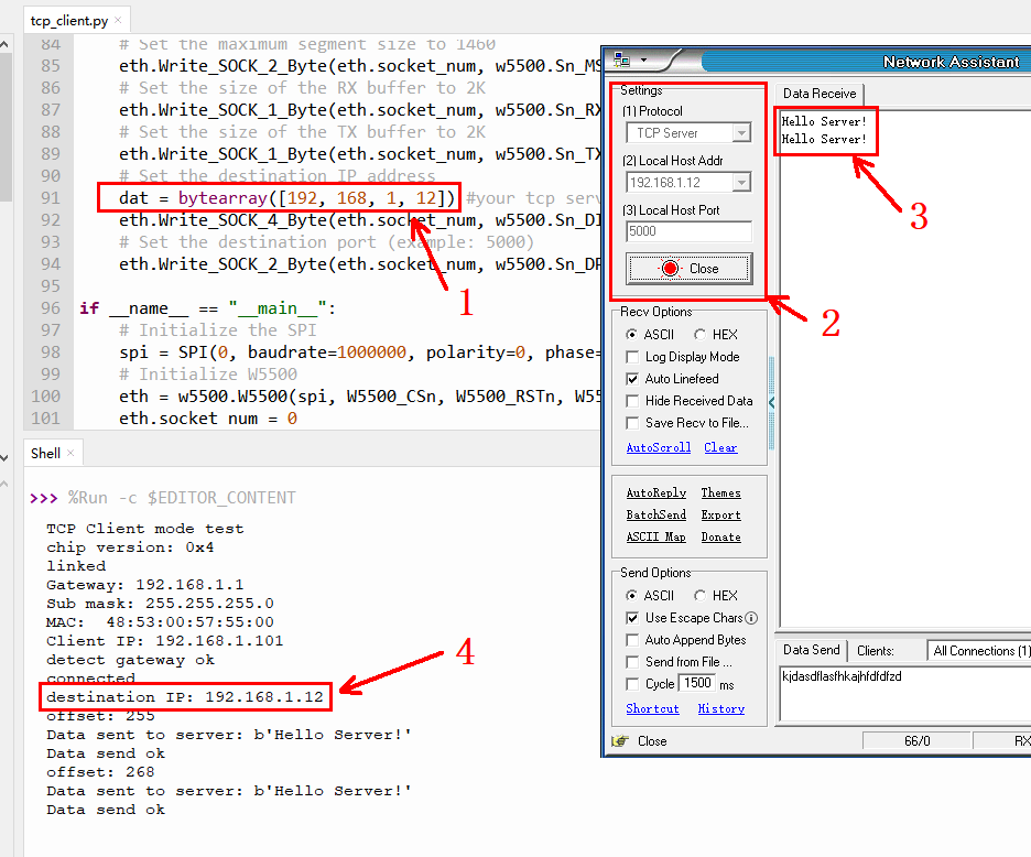
Double-click to open the tcp_client.py file. Then, modify the values indicated by the red arrows in Figure 2-7 to match your network environment. Ensure your W5500 and PC are on the same local area network.
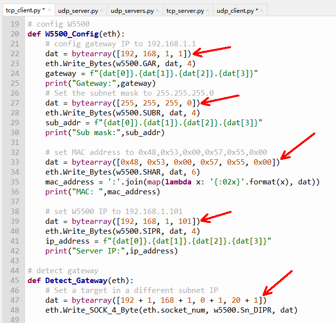
Figure 2-7
In the Socket_Config function, the statement dat = bytearray([192, 168, 1, 12]) represents the server's IP address. This needs to match your PC's IP address, so you should modify the value of this statement according to your PC's IP (as shown at '1' in Figure 2-8).
After configuring the network environment parameters, click the "Run current script" button (or press F5) to execute the code. Then, double-click the NetAssist.exe file within the SocketTest folder to open the network debugging assistant. Set the mode and parameters according to your network environment, as indicated at '2' in Figure 2-8. Next, click the "Open" button. Upon successful connection, this button will change from gray to a red "Close." Concurrently, connection information will appear in the shell window at the bottom of the Thonny software, as shown at '4' in Figure 2-8. Following this, the W5500 will send "Hello Server!" messages to the PC every second, as indicated at '3' in Figure 2-8.
TCP Server Mode
The tcp_server.py file primarily enables the W5500 to function as a server. The functionalities implemented in this code are largely consistent with tcp_client.py.
The key difference is that the W5500, acting as a server, waits for a client to connect. Once a connection is successfully established, the W5500 will receive data sent from the client and then echo all received data back to the client.
Refer to Figure 2-9 for the connection diagram.
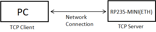
Figure 2-9
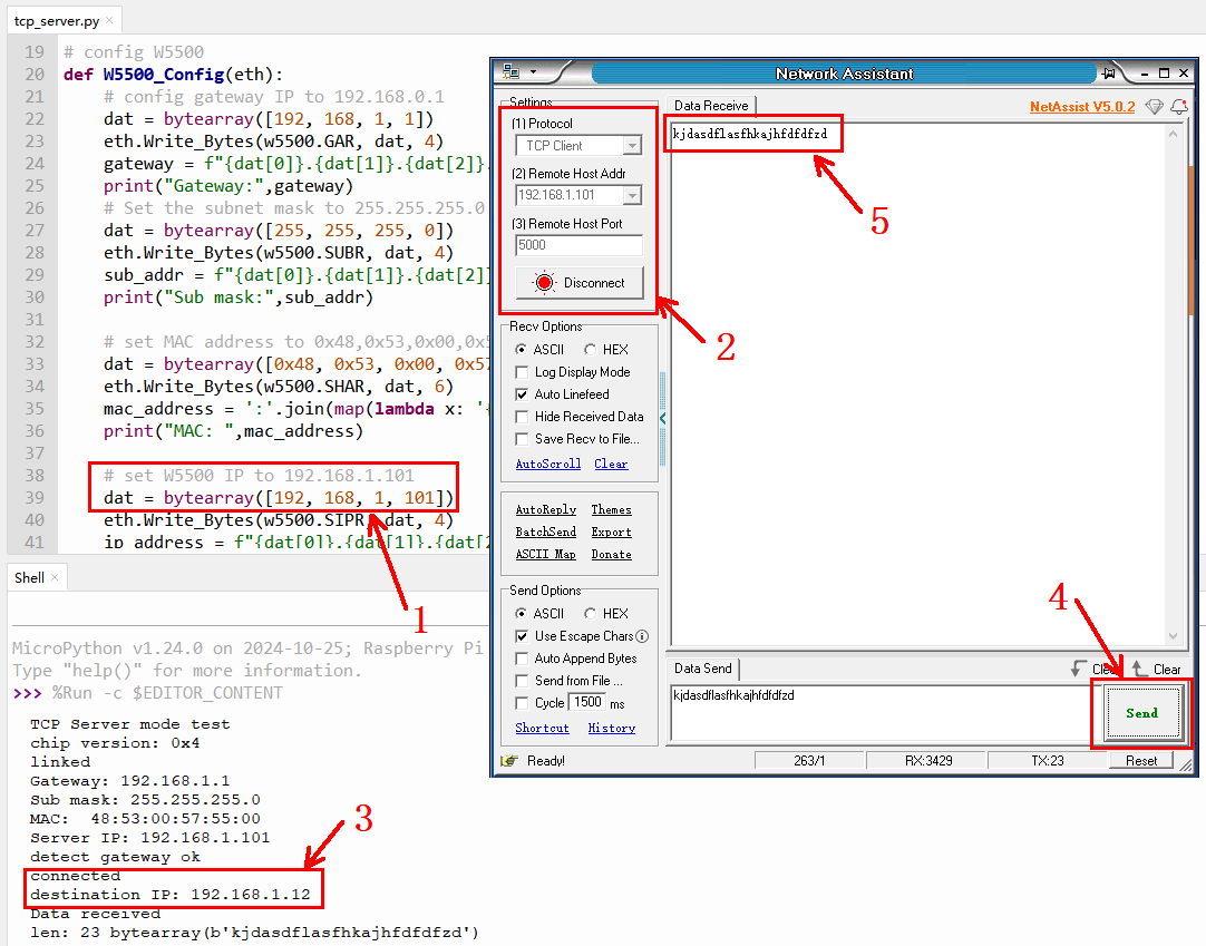
As shown in Figure 2-10, set the W5500's IP address at '1' (this will be its server IP). Then, open the network debugging assistant, NetAssist. At '2' in Figure 2-10, select "TCP Client" and enter the IP address (matching the IP set at '1' in Figure 2-10) and port number (set in the Socket_Config function, default is 5000). Click the gray "Connect" button. Upon successful connection, the button will turn red, displaying "Disconnect." Concurrently, the shell window will print the PC's IP address (as the TCP client), as shown at '3' in Figure 2-10. Next, enter the data you wish to send to the W5500 in the "Data Send" window of the NetAssist software, then click the "Send" button (see '4' in Figure 2-10). The W5500 will then echo the received data back to the PC, as shown at '5' in Figure 2-10.
UDP Server Mode
UDP Server communication offers both single-connection and many-to-one connection modes. udp_server.py serves as the example program for a single connection, as shown in Figure 2-11, while udp_servers.py is the example for multiple connections, as shown in Figure 2-12.
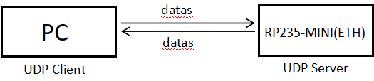
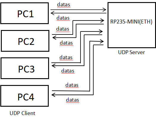
Figure 2-12 UDP Multiple Connection Mode
For single-connection mode, as shown in Figure 2-11:
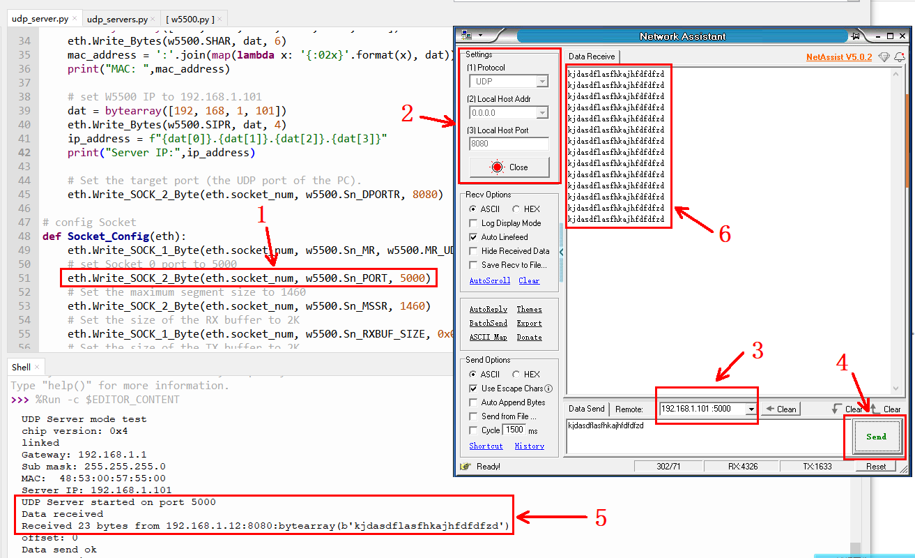
First, in the Socket_Config function, set the W5500's port number (see '1'). In the NetAssist network debugging assistant, set "Local Host Addr" to your PC's IP or "0.0.0.0". For "Local Host Port", you can generally use any unused port within the range of 1024 to 65535 (ports 1 to 1023 are typically system-reserved). Click "Open."
Next, at '3' in Figure 2-13, enter the W5500's IP address and socket port number. For the udp_server.py example, use 5000. For udp_servers.py, you can use any value between 5000 and 5003. Finally, enter your desired content in the "Data Send" window and click the "Send" button. You'll then see the data received by the W5500 and the data returned to the client, as indicated at '5' and '6' in Figure 2-13.
UDP Client Mode
The
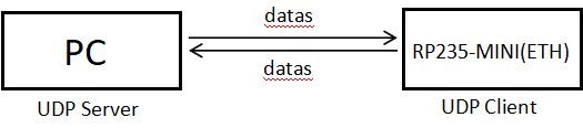
udp_client.py file corresponds to the UDP Client mode. As illustrated in Figure 2-14, once the client (using the NetAssist network debugging assistant) successfully connects, the W5500 will proactively send data to the PC (acting as the server).
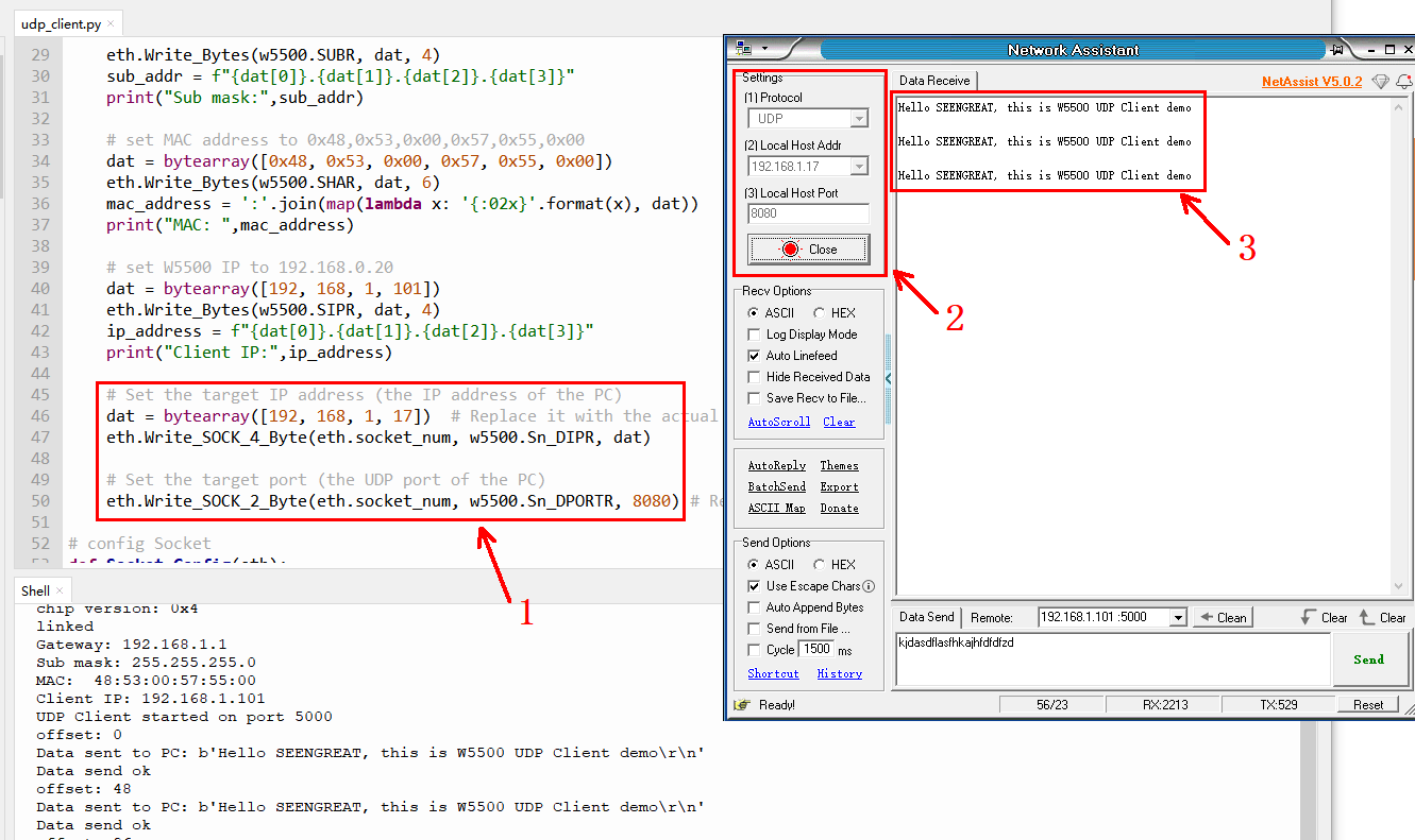
At '1' in Figure 2-15, set your PC's IP address and port according to your network environment. Then, open the NetAssist network debugging assistant and, at '2', configure the same parameters as those set at '1'. Click "Open." The W5500 will then automatically send data to your PC, as shown at '3' in Figure 2-15.
Arduino Example Programs
Arduino IDE Installation
You can download the Arduino IDE installer package from the official Arduino website:
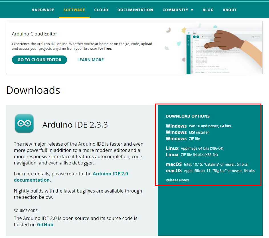
Figure 2-16
Select "JUST DOWNLOAD" on the page that appears.
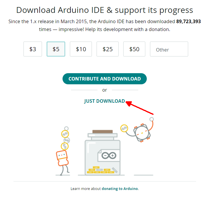
Figure 2-17
After the installer package downloads, proceed with the installation. If prompted to install drivers during the process, simply click Install.Arduino IDE Configuration
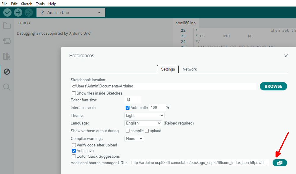
Open the Arduino IDE. Go to File > Preferences, then click the button in the lower right corner of the pop-up window (as indicated by the red arrow in Figure 2-18).
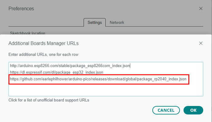
In the pop-up window, add the following URL:
https://github.com/earlephilhower/arduino-pico/releases/download/global/package_rp2040_index.json
This should be placed in the area indicated by the red box in Figure 2-19.
Next, click Tools > Board: > Boards Manager... Then, type "pico" into the search bar. In the results, locate the entry shown within the red box in Figure 2-20 and click the "INSTALL" button. Wait for the installation to complete.
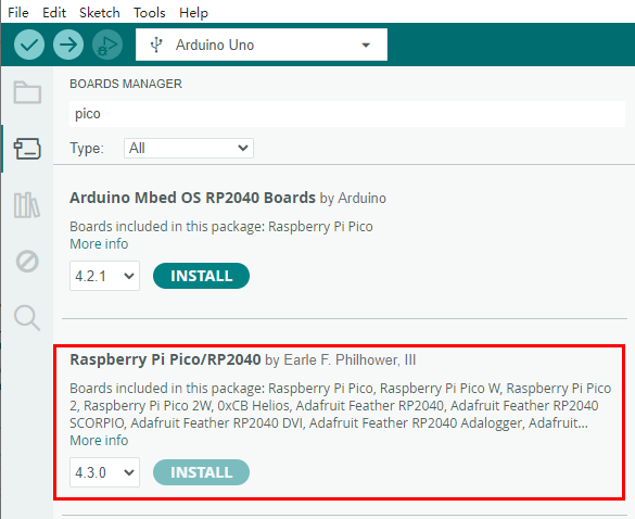
If the installation fails, you can also download the RP2040 compressed package. Extract the rp2040 folder and copy it to the following path: \Users\[username]\AppData\Local\Arduino15\packages. Replace [username] with your computer's actual username.
- With the RP2350-MINI(ETH) board powered off, press and hold the BOOT button (see ⑥ in Figure 2-1).
- Connect the board to your computer using a USB cable, then release the BOOT button.
- Your computer should now display a removable disk directory named "RP2350."
- After downloading the demo codes, double-click to open the
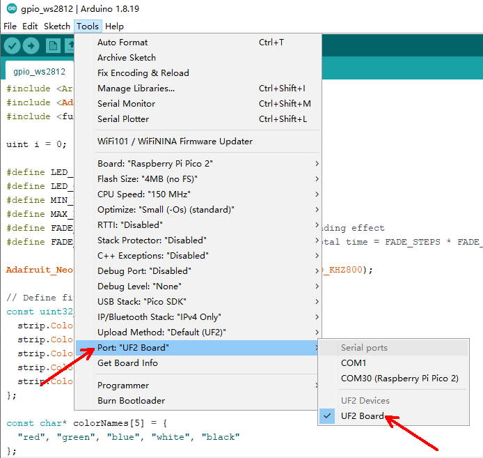
gpio_ws2812.inofile located in\Arduino\gpio\. - Then, go to Tools > Port > UF2 Board, as shown in Figure 2-21.
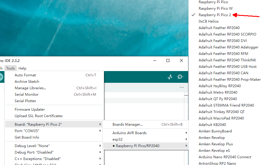
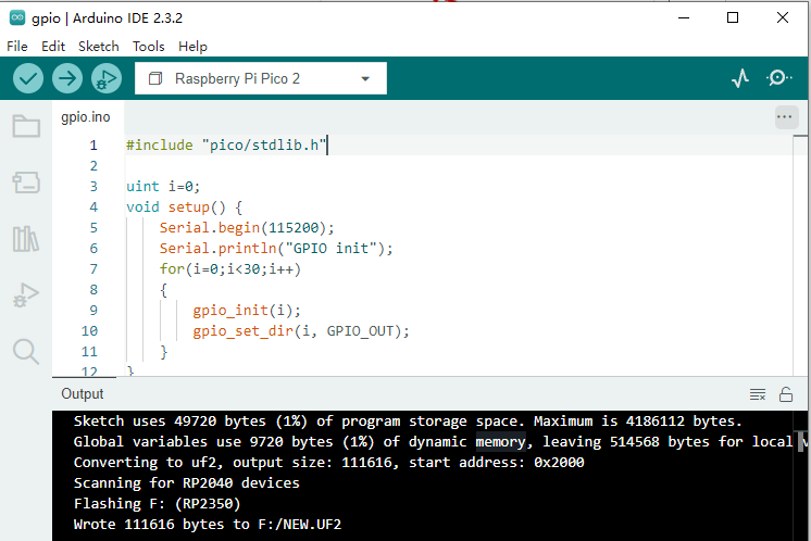
Next, go to Tools > Board > Raspberry Pi Pico/RP2040 and select Raspberry Pi Pico 2, as shown in Figure 2-22. Then, click the "Upload" button to begin the upload process. Once the upload is complete, your screen will look like Figure 2-23.
Running gpio_ws2812
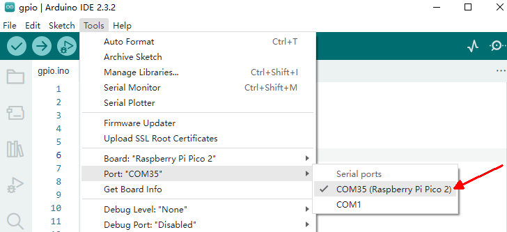
Select Tools > Port > COM35 (Raspberry Pi Pico 2), as shown by "COM35" in Figure 2-24. Note that the port number may vary for different boards. If the port isn't detected, try power cycling your RP2350-MINI(ETH) board.
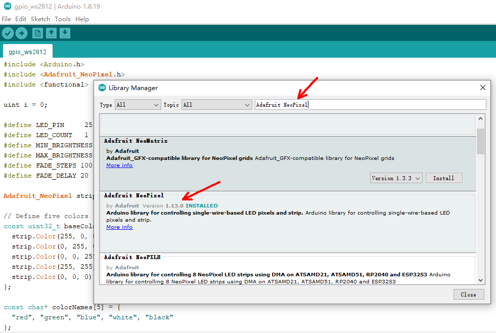
Open the gpio_ws2812.ino file. Then, navigate to Tools > Manage Libraries... and type "Adafruit NeoPixel" into the search bar. Locate the library in the results and click the "Install" button in the lower right corner, as shown in Figure 2-25.
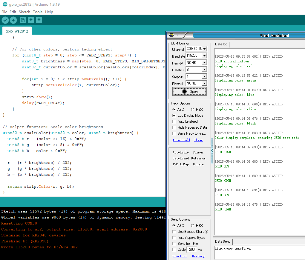
Click the "Upload" button to upload the program. Once the upload is complete, open the serial monitor to view debugging information.
You'll see the WS2812 LED illuminate sequentially in red, green, blue, and white, then turn off. Following this, the GPIO output will begin: as shown in Figure 2-26, all GPIO pins on the board will toggle their logic level every 2 seconds.
Network Testing
For configuring example programs related to other network testing functionalities, please refer to the Python network examples.
VS Code Example Programs
For C/C++ development, we recommend using Pico VS Code. You can set up your development environment by following the official Raspberry Pi tutorial here:
Program Flashing
- With the RP2350-MINI(ETH) board powered off, press and hold the BOOT button (refer to ⑥ in Figure 2-1).
- Connect the board to your computer using a USB cable, then release the BOOT button.
- Your computer should now display a removable disk directory named "RP2350."
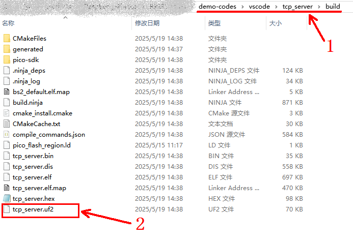
- Drag and drop the
.uf2file (e.g.,tcp_server.uf2) from thebuildpath of the corresponding project file in yourdemo codes/vscodedirectory into the "RP2350" disk, as shown in Figure 2-27.
Network Testing
For configuring example programs related to other network testing functionalities, please refer to the Python network examples.
Resources
Schematic
Example Programs
Official Documentation
- Pico 2 Getting Started Guide
- Pico 2 C SDK Guide
- Pico 2 Python SDK Guide
- Pico 2 Schematic
- Pico 2 Datasheet
- Pico 2 Hardware Design Reference
- Raspberry Pi Official C/C++ Examples
- Raspberry Pi Official MicroPython Examples
- Arduino Official C/C++ Examples
- RP2350+W5500 Official Documentation
- Network Test Tools
- Serial Debugging Tools